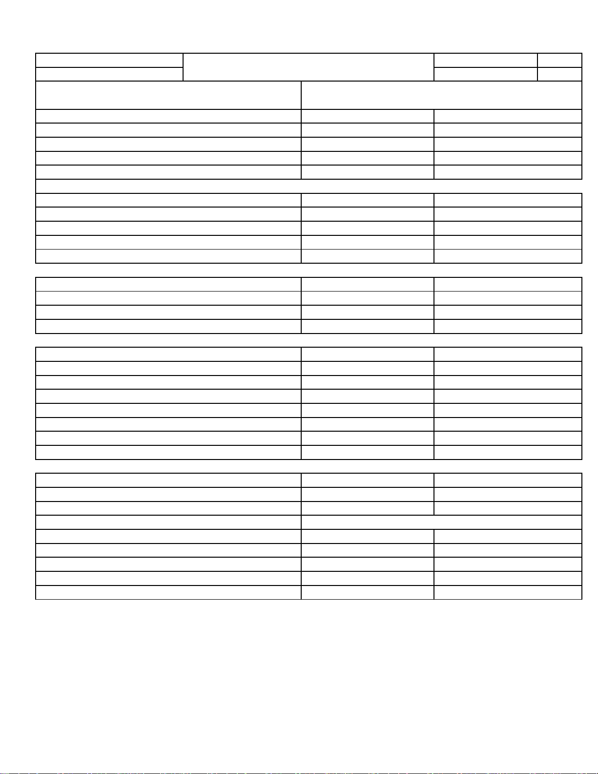
ConnectingRods
BearingClearance(WithCrush)
SideClearance
PistonPinBoreDiameter
BearingBoreOutofRound(Max.)
CrankshaftMainBearingJournals
Diameter
BearingClearance
OutofRound(Max.)
CrankshaftEndPlay
CrankshaftRodBearingJournals
Diameter
BearingClearance
OutofRound(Max.)
CamshaftJournalDia.&Clearance
BoreDia.CamTowerNo.1
BoreDia.CamTowersNo.2,3,4
JournalDia.No1
JournalDia.No.2,3,4
ClearanceNo.1
ClearanceNo.2,3,4
CamshaftEndPlay
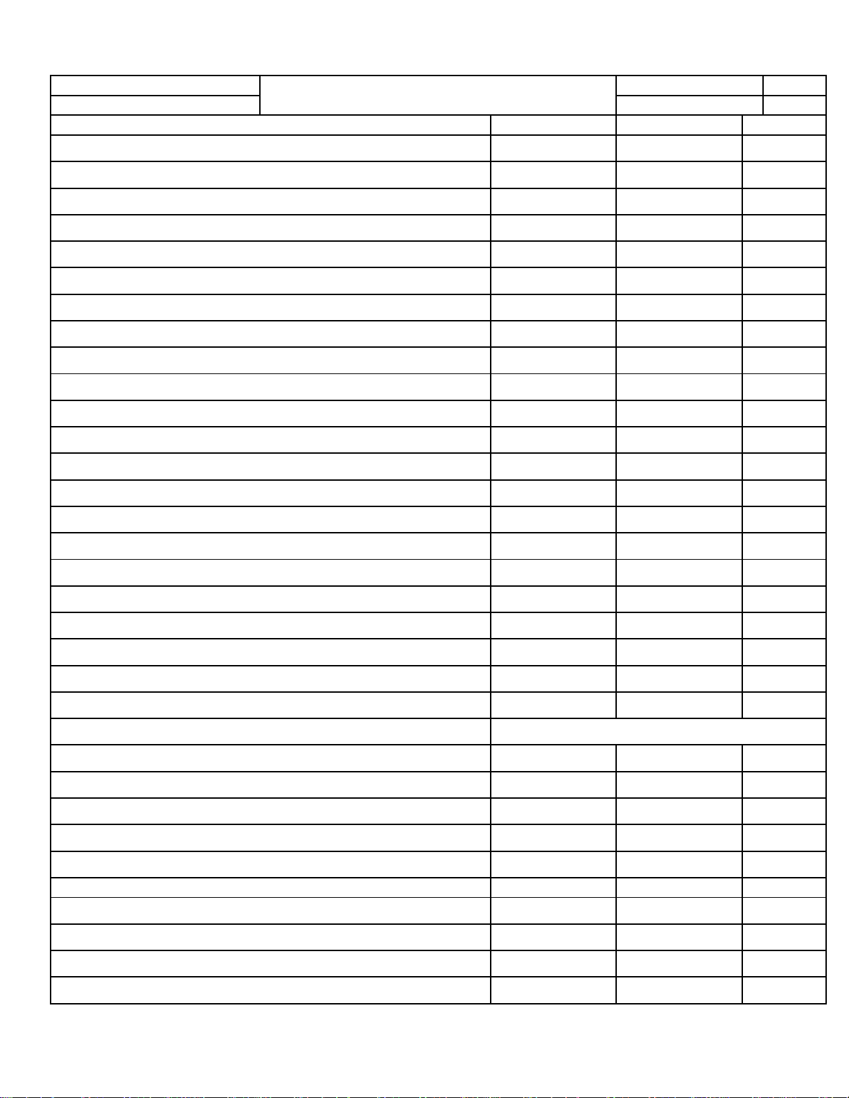
CylinderHead
CompressedGasketThickness@FireRing
CylinderHeadDeckFlatness
ValveSeatAngle
IntakeValveSeatWidth
ExhaustValveSeatWidth
ValveGuideBoreDiameter
ValveStemtoGuideClearance(Intake)
ValveStemtoGuideClearance(Exhaust)
6.00‐6.02mm 0.236‐0.237in.
0.023‐0.061mm 0.0009‐0.0024in.
44.75°±0.25°fromthevalveguideaxis
0.030‐0.068mm 0.0012‐0.0027in.
1.0‐1.2mm 0.04‐0.05in.
1.41‐1.61mm 0.055‐0.063in.
Metric Standard
0.48‐0.60mm 0.019‐0.024in.
0.09mm 0.0035in.
0.024‐0.064mm 0.0009‐0.0025in.
0.008mm 0.0003in.
0.075‐0.251mm 0.003‐0.010in.
23.977‐23.996mm 0.9440‐0.9447in.
0.025‐0.065mm 0.001‐0.0026in.
32.020‐32.041mm 1.2606‐1.2615in.
24.020‐24.041mm 0.9457‐0.9465in.
31.976‐31.995mm 1.2589‐1.2596in.
0.023‐0.064mm 0.0009‐0.0025in.
0.005mm 0.0002in.
Metric Standard
Metric Standard
59.0±0.009mm 2.3228±0.0035in.
0.050‐0.290mm 0.002‐0.0114in.
71.996±0.009mm 2.8345±0.0035in.
0.024‐0.050mm 0.0009‐0.0020in.
0.005mm 0.0002in.
0.070‐0.370mm 0.0028‐0.0146in.
22.016±0.005mm 0.8668±0.0002in.
Metric Standard
Description Specification
Metric Standard
0.023‐0.064mm 0.0009‐0.0025in.
ChryslerIIIHEngineSpecifications
RevisionDRAFT Section 1
Mar‐16 Sheet 2