Chungho Iguassu CT II User manual

Technical & Repair guide for ChungHo Iguassu CT II
call 888.758.1234 for further technical support
IGUASSU CT II
Technical Manual

2
Table of Contents
1. Designation of Components
1-1. Front
1-2. Back
2. Product Features
3. Exploded Diagram & Parts List
4. System Diagram
4-1. Water Purication Procedure
4-2. Cooling System Diagram
5. Distribution Line Diagram
6. Product Specication
7. Installation Precautions
8. Installation
9. Usage
9-1. Select/Deselect Function
9-2. Water Dispensing
9-3. Operational Beep
10. System Formation
10-1. Functional Formation
10-2. Flow Restrictor
11. System Malfunction Diagnosis & Repair Procedure
12. System Disassembling
13. Filter Changing
14. Water Draining
15. Tank Cleaning
16. Parts Replacing
page 3
page 4-5
page 6-7
page 8
page 9
page 10
page 11
page 12
page 13-14
page 15-16
page 17-25
page 26-27
page 28
page 29
page 30
page 31-43

3
1
Designation of Components
Designation of
Components
Hot Water Touch Sensor Button
Hot Water Display
Hot Water ON/OFF Switch
Hot Water Dispensing Button
Ambient/Cold Water
Touch Sensor Button
Water Full Display
Cold Water Display
Ambient Water Display
Hot Water Operation Display
Ambient/Cold Water
Dispensing Button
1-1 FRONT
1-2 BACK

4
Product Features 2
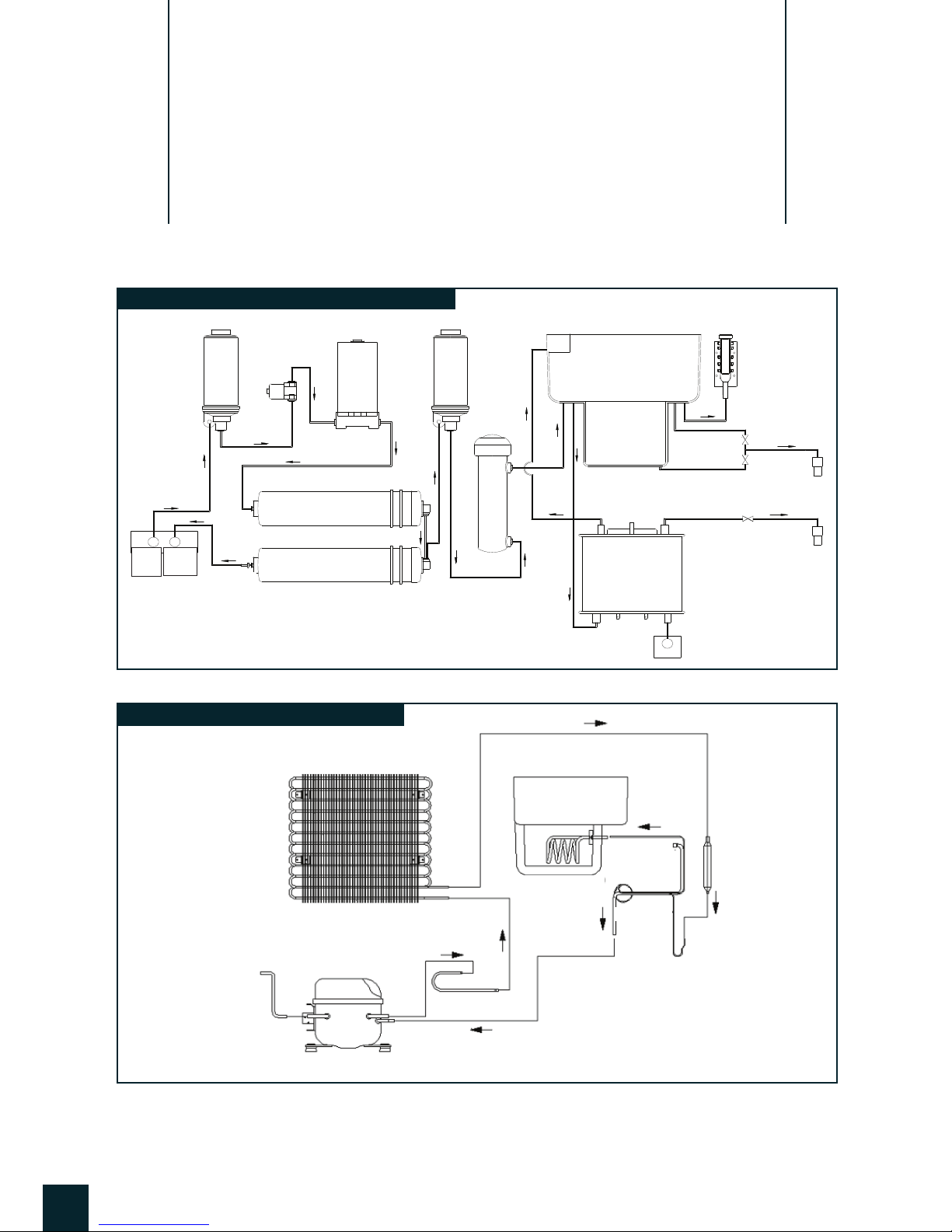
24 Hour natural water circulation system (N.W.P.W.)
This function of ChungHo purication systems is designed to allow water to continuously ow for 24
hours within the water purier by adopting a natural circulation method. This mode, entitle N.W.P.W.,
applies the natural weight of water pressure in order to always supply clean and fresh water.(Patent:
No.105585)
Energy saving function
The economically designed Iguassu Ice delivers puried water to the ice making unit in order to make
pure ice while simultaneously sending cooled water to cold water tank. This allows the system to
maintain a constant cold water temperature, thus inherently preventing water waste and helping to
conserve energy.
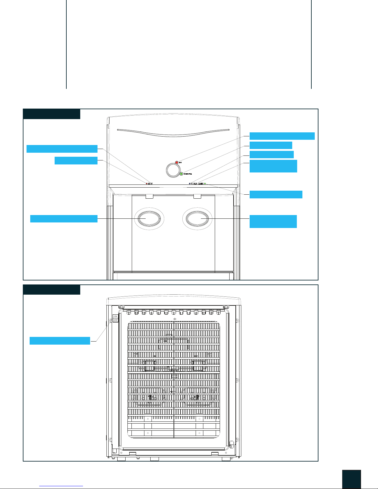
Touch sensor application
Breaking away from traditional button applications, the Iguassu CT II has a built- in touch sensor ap-
plication. This addition has been integrated into the already stellar system with customer convenience
in mind. The easy-to-use sensor application allows for eortless and enjoyable drinking water.
Infrared water level detection
With improved detection accuracy, as compared to existing mechanical detection types, the infrared
OLC sensor applies an electronic water level sensor that was developed for stable water level detec-
tion. The signal is connected to a controller in order to automatically adjust puried water levels.(Pat-
ent: No.426182)
Standard hot water safety function
(Hot water locking function + Hot water automatic selection / Release function)
Setting the hot water locking function using the Hot Lock touch sensor button prevents hot water
from being dispensed from the unit. This is in order to prevent burns and other unwanted injuries to
children, the elderly and any other vulnerable user. As a furthered safety procedure, you will nd that
upon the use of hot water and the releasing of the hot water lock, the system, after a certain period
of time, will automatically shut o the hot water even though the hot water release button has been
pressed.
System Display functions and safety reinforcement
The safety features of the product have been enhanced in order to prevent various problems from
occurring. The system will inform the user(s) of abnormal occurrences through a ashing display icon
and by automatically stopping the ice making function, cold water function, and water purication
function when an abnormality in the system is detected.

5
Beep function
This provides customers a convenient reminder that a system setting has been changed as sounded
via beeping(ding~, dingdong~, etc.) and as applied via system touch sensors.
Wire condenser(Natural convection)
Using natural convection, the system wire condensers are rated to reduce noise and thus provide
further convenience for the user.
Convenience in use
Function operations are designed as simply as possible in order to maximize convenience.
Environment friendly coolant
The Iguassu CT II has adopted an environmentally friendly cooling system in the new R-134a, a cool-
ant that will not add to the problems of ozone layer destruction and global warming.
Default function
Designed to automatically convert to cold water mode when in queue.
Product
Features

6
3
Exploded Diagram & Parts List
EXPLODED DIAGRAM

Exploded Diagram &
Parts List
PARTS LIST
7
refer pg.6 for picture of the parts
Drip Tray
Hot water ON
Hot water
Ambi Dispense
Hot Dispense
Hot tank IN
Hot water drain
Hot water ON S/W
Stabilizer - Elec.
Stabilizer PCB Cover
TUBE-faucet Cold/Ambi
only
only
only
Cold Dispense
Cold water sensor
Cold water separator
Rotation Cover sealing
Tank Cover sealing
Rotation Cover
Aircap Cover
x
x
Insulate - Cold NIPPLE
Insulate - Cold Sensor
Insulate - Cold tank
Insulate
Hot water
dispensing Sol V/V
dispensing Sol V/V MPPE
MPPEInlet Sol V/V
Cold/Ambi
water temp. select
temp. select
Water Full
RUBBER-Dispensing btn.
Dispensing button.
Dispensing Button Cover

4
System Diagram
냉정수기(CHP-2240D, 2241D)
CHP-2240D, 2241D 흐름도
* CHP-2240D는 자외선 살균기 없음
Pre Carbon
Raw
Water Auto
Flushing
Valve
Solenoid
Valve
Ambient Water Sol. V/V
Cold Water Sol. V/V
Sub
Tank
Hot Water Sol. V/V
Hot
Cleaning
Valve
Hot Water
Dispensing
Ambient/Cold
Water Dispensing
Flushing
water
Level Sensor
Ambient
Water Tank
Cold
Water Tank
Hot
Water Tank
Membrane
Post Carbon
UV Filter
Sediment
Booster
Pump
* UV - optional
8
4-1. WATER PURIFICATION PROCEDURE
4-2. COOLING SYSTEM DIAGRAM
Condenser
Evaporator
S-Pipe Assy
Capillary Tube
(Diabatic)
Compressor
D-Pipe
Drier
Coolant Input

5
Distribution Line Diagram
9

6
Product Specication
10

7
Installation Precautions
11
When installing the product, do not install it at the following places.
- Near re
- Near ammable material
- Wet place
- A place exposed to rain and snow
- A place exposed to direct sunshine
- Near chemicals (volatile material, organic solvent, etc.)
- A place below 32°F or a place with the possibility of dropping below 32°F
Use the following water quality ramge.
- Water Pressure : 7~120 psi (0.5~8.4 kgf/cm2)
- Water Temperature : 39 ~ 100°F (4~38°C)
- pH : 5 ~ 10 - Hardness : 300 ppm or less - Evaporation remains : 500 ppm or less
- Water Quality : Biologically safe water quality
If you do not use water quality within the above range without prior discussion of our company, the
product can be excluded from the stated warranty period.
When transporting the product, do not tilt it over 45°.
Severe tilting can be the cause of reduced performance.
A bad wall outlet or plug may cause an electric shock or re, do NOT use them.
Do not connect hot water(over 100°F) to this product.
Leave approximately 6 in, between the wall, sides and rear surfaces of the product so that
ventilation may be smoothly performed for safe operation of product.
When connecting tubing hose, take care so that the tubing hose is not be bent or pressed down
by heavy objects, etc
If tubing hose in blocked, water does not ow smoothly and may cause malfunction of the product.
Adjust the hose so that the water discharged from the drainage hose may not splash onto the
product’s surroundings.
Brine water, or the water coming out through drainage lines, can easily be applied towards other wa-
ter related needs, such as in bathroom cleaning, house cleaning laundering, washing, etc. in order to
prevent waste of water. However, never use the brine water as drinking water or for cooking of food.
Raising the brine water and drain water over 1 ft. above the installation surface, or connecting
them over 6 ft. away from the water purier can hinder a smooth drainage process. In order to
install the product in a location where the brine water and drained water line are located a dis-
tance of over 6 ft. from each, the user will inevitably have to install a separate drainage pump.
When installing another product (water purier, shower softener, etc.) at the same location and
the water is derived from the same installation source, prepare an independent drain line for
each product.
7

8
Installation
12
1
2
3
4
5
6
7
8
9
10
11
Install the product on a level surface. (Change product level using the product
leg adjustment and conrm the level surface a level.)
Close o the water supply valve as supplied to each household. Then tempo-
rarily remove the connector part as provided from your given water source.
Then connect the main water line adaptor.
If the sealing O-ring at the connection piece is removed or damaged, it can lead to
leakage.
Connect tubing hose into water source adaptor and then attach to the water
inlet on the rear side of product.
If tubing hose in blocked, water does not ow smoothly and may cause malfunc-
tion of the product.
Connect tubing hose into the removed water(brine) and drained water con-
nection part on the rear side of product and then connect tubing hose into the
drainage hole in sink, bathroom, or multi-purpose room, etc.
Install the removed water(brine) line and drained water line separately. If drainage
dose not function properly due to improper installation, then water may ow back
toward waterspout and cause an overow.
Adjust the tubing hose so that the discharged water(brine) and tap water tub-
ing hose so that they do not splash into surrounding areas.
Open the tap water valve supplied into each household, and place the water
source adaptor to the open position.
Check to see if water is leaking at each connection part.
For stabilization of the cooling system and for safe use of this product, insert
the power plug into an AC 110V60Hz, 220V50Hz, 240V/50Hz and 220V/60Hz
power outlet after 30 minutes after the installation of the product.
Check whether water is supplied into the inside of product and whether there
is any leakage in or around the tubing connections.
Check whether water is coming out by pressing the water dispensing button 1
hour after purication has begun.
Use after water has owed into the storage tanks.
8

9
Usage
13
Ambient / Cold Water Function
There are no special setup or release functions on ambient and cold water operation. It operates auto-
matically in terms of program controlled by PCB when the power supply is on.
Hot Water Operation Setting
If hot water operation display LED is turned on by setting the hot water operation switch to“ON” posi-
tion, the hot water system will operate. How water system is operated by a detection sensor which
automatically detects the temperature inside of the hot water tank.
Hot Water Operation Release
If the hot water operation display LED is turned o by setting the hot water operation switch to“OFF”
position, then the hot water system stops.
*After the hot water operation switch is turned o, be careful not to be burned when you take the hot water.
Hot Water Dispense Mode
If HOT (hot water selection) touch sensor button is selected, the hot water selection LED (Red) turns
the light on. It is the selection of hot water dispensing.
* If the hot water LED (Red) is not turned on, the hot water won’t come out even though the hot water
dispensing button is pressed.
If you press hot water dispenser button, you can take hot water.
Release hot water dispensor button after you nish dispensing hot water.
* The hot water dispensing stops when HOT (hot water dispensing selection) touch sensor button is
touched.
If you don’t take hot water any more, hot water dispensing function is released auto-
matically after 5 seconds from nishing hot water dispensing.
* Even if the hot water operation LED display (HOT) is turned o, you can take the water in the hot water storage tank after
selection HOT (hot water dispensing selection) touch sensor switch button.
Cold Water Dispense Mode
Basically, it always sets on the position of cold water.
(Light on BLUE on LED display)
* When you want to take cold water after dispensing ambient water, please touch COLD/AMBI (cold water/ ambient water
dispensing selection) touch sensor button.
It start to dispense cold water by pressing cold water dispenser button.
* The cold water is dispensing even if AMBI (ambient water dispensing selection) touch sensor button is
selected while cold water is dispensing.
Release cold water dispenser button after you nish dispensidng cold water.
9-1 SELECT / DESELECT FUNCTION
9-2 WATER DISPENSING
9
9
1
1
2
2
3
3
4

14
Ambient Water Dispense Mode
Touch AMBI (ambient water dispensing selection) touch sensor button.
(Light on GREEN on LED display)
* If the ambient water LED (Green) is not turned on, the ambient water won’t come out even though the ambient water
dispensing button is pressed.
If you press ambient water dispenser button, you can take ambient water.
Release ambient water dispensor button after you nish dispensing ambient water.
* The hot water dispensing stops when HOT (hot water dispensing selection) touch sensor button is
touched.
If you don’t take ambient water any more, ambient water dispensing function is re-
leased automatically after 10 seconds from nishing ambient water dispensing.
*After the hot water operation switch is turned o, be careful not to be burned when you take the hot water.
* While dispensing cold/ambient water, it is possible to take hot water
* When you don’t use the unit some period of time after dispensing ambient water, the unit converted to cold water
dispensing selection mode which is high frequency usage. (Default function)
9-3 OPERATIONAL BEEP
9-2 WATER DISPENSING
1
2
3
4
10
Product
Usage

10
System Formation
15
10-1 FUNCTIONAL COMPONENTS
Transformer & Sensors
1. Transformer : IN - AC220V/60Hz, OUT - AC21V/ 1.9A
2. Cold Water Sensor : NTC Type(PX-42H : 0°C 27.62 kΩ)
3. Hot Water Sensor : NTC Type(PT3-312 : 25°C 231.4 kΩ)
4. Optical Water Level Detector : OLC-S1
Purication System
1. Booster Pump : DC 24V, 650mA
2. Inlet Solenoid V/V : DC 24V, 250mA
3. Water level Detector (OLC-S1)
4. Flow Restrictor (page 16)
Dispensing System
1. Water Dispensing Sol V/V : DC 24V, 420mA(low pressure)
- Hot/Cold/Ambient Water Dispensing Sol V/V 1EA
2. Dispensing Button : Waterproof Micro S/W 2EA
- Hot/Cold and Hot Water Dispensing Button : 1EA
Cold Water System
1. Compressor : 88W, 680mA(Coolant: R-134a )
2. Radiant Heat : Wire Condenser Type
3. Cold Water Sensor (NTC Thermistor)
4. Water Temp. : 4.0°C ~ 5.0°C (Controller Dip SW1 OFF, Default)
4.5°C ~ 5.5°C (Controller Dip SW1 ON)
Cold Water System
1. Hot Water Sensor (NTC Thermistor)
2. Manual Bimetal 105N : OPEN - 105°C
3. Sheath Heater: AC220V, 150W
4. Water Temp : 80°C ~ 82°C (Controller Dip SW2 ON)
83°C ~ 85°C (Controller Dip SW2 OFF, Default)
Green PCB – 4 Point
1) Cold/Hot Water Operation
2) Re-activiation
3) Water full detection
4) Overow detection
Hot/Cold Water Operation Point
OLC-S1 Connector : YH025-06
OLC-S Connector : SMH250-06

16
System
Formation
1) Flow Restrictor
Control Waste Water Amount (Alternated of AFV)
2) Position
Located into the Membrane waste tubing line
Caution
1. Disconnect Stem Elbow when replace
membrane lter. (Do not separate tuning
line with the Stem Elbow.
2. If once tubing separated with the Stem
Elbow, Flow Restrictor & Stem Elbow
both should be replaced for new.
3. Must ush for 30 seconds when replace
Pre-carbon lter. If not, it causes Flow
Restrictor clogging.
10-2 FLOW RESTRICTOR

11
System Malfunction Diagnosis &
Repair Procedure
17
Table of Contents

18
Trouble
Shooting
Detach top cover and right side cover, then nd
fuse holder.
Find transformer located at base plate of the unit
then check its IN/OUT connection and voltage.
(INPUT : AC110V, OUTPUT : AC21V)
Check if the transformer OUTPUT is connected to
controller correctly.
- Check wire connection.
Check fuse inside the fuse holder if it is opened.
> Replace fuse if it is faulty.
> Replace transformer if it is faulty.
> Replace controller if connected correctly.
11-1 POWER MALFUNCTION
Symptom
In case of LED display o although power connected.
Terminal 1 & 2
1
2
3
4

19
Trouble
Shooting
Check if there is water membrane on top of Mesh-
OLC-S1 and medium lter area on the water tank.
Check wire connection of OLC and water level in
the tube.
- Overow : Overow LED blinks
- Loosen OLC connection : Overow LED blinks
Check water level in tank and check silicon tube
connection if there is water leak.
Check water supply valve is opened.
11-2 FILTRATION MALFUNCTION
Check OLC and ltration process works properly.
Check Membrane
1
2
3
4

20
Trouble
Shooting
Check hot/cold/ambient water dispensing solenoid
valves.
- Check its voltage is DC24V supplies to Sol V/V at
terminal when dispensing.
- Check if there is leak of each Sol V/V.
- Check wire connection
Red : Hot Water Dispensing Sol V/V
White : Ambient
Blue : Cold
If still not DC 24V supplies, check controller and
wire connection.
- Check wire connection
- Check output voltage at controller.
> If not, replace Sol V/V
> Replace Controller if it is faulty.
11-3 WATER DISPENSING (SOL V/V MALFUNCTION)
Faulty water dispensing solenoid Valve (Hot/Cold/
Ambient) causes water dispensing malfunction.
DC 24V
- Cold : Terminal 3 & 6
- Ambient : Terminal 4 & 6
- Hot : Terminal 5 & 6
Hot ColdAmbient
1
2
Table of contents
Other Chungho Water Dispenser manuals
Popular Water Dispenser manuals by other brands

Plasmatic Systems
Plasmatic Systems PLASMA-PREEN I user manual

Eureka Forbes
Eureka Forbes Aquaguard select AWS C3500 DX user manual

Osmio
Osmio MINISOFT user manual

Avalon
Avalon A9 Use and care guide

Halsey Taylor
Halsey Taylor Contour Series owner's manual

Nephros
Nephros HydraGuard 10" UltraFilter - Flush Instructions for use

Lenoxx
Lenoxx Healthy Choice UR10 instructions

IBC Water
IBC Water AS0715MP-960 Installation & operating instructions

TrojanUV
TrojanUV TrojanUVMax A owner's manual

Aqua Cooler
Aqua Cooler PT30 Series Usage and Care Manual

GE
GE GXSF30V02 Owner's manual and installation instructions

Philips
Philips ADD4954 user manual