CiA TVV420S User manual
- 1 -
4channelsdigitalvideo-recorder
I
In
ns
st
ta
al
ll
la
at
ti
io
on
n/
/O
Op
pe
er
ra
at
ti
in
ng
g
m
ma
an
nu
ua
al
l
(REV1.00)
- 2 -
These symbols with supplemental markings are at the rear of the DVR system.
■Explanation of Symbols
The lightning flash with arrowhead symbol, with an equilateral triangle, is
intended
to alert the user to the presence of uninsulated "dangerous voltage" within the
product's enclosure that may be of sufficient magnitude to constitute a risk of
electric shock to persons.
The exclamation point within an equilateral triangle is intended to alert the user
to the presence of important operating and maintenance (servicing) instructions in
the literature accompanying the product.
WARNING : TO REDUCE THE RISK OF FIRE OR ELECTRIC SHOCK, DO NOT EXPOSE THIS
UNIT TO RAIN OR MOISTURE.
NOTE : This equipment has been tested and found to comply with the limits for a Class A
digital device, pursuant to part 15 of the FCC Rules. These limits are designed to provide
reasonable protection against harmful interference when the equipment is operated in a
commercial environment. This equipment generates, uses, and can radiate radio frequency
energy and, if not installed and used in accordance with the instruction manual, may cause
harmful interference to radio communications.
Operation of this equipment in a residential area is likely to cause harmful interference in
which case the user will be required to correct the interference at his own expense.
The user may find the following booklet prepared by the Federal Communications Commission
helpful :
HOW TO IDENTIFY AND RESOLVE RADIO-TV INTERFERENCE PROBLEMS.
This booklet is available from the US Government Printing Office, Washington, DC 20402,
Stock Number004-000-00345-4
CAUTION : CHANGES OR MODIFICATIONS NOT EXPRESSLY APPROVED BY THE PARTY
RESPONSIBLE FOR COM PLIANCE COULD VOID THE USER’S AUTHORITY TO
OPERATE THE EQUIPMENT.
IMPORTANT SAFEGUARDS AND WARNINGS
CAUTION
RISK OF ELECTRIC SHOCK
DO NOT OPEN
CAUTION: TO REDUCE THE RISK OF ELECTRIC SHOCK, DO NOT REMOVE COVER,
NO USER-SERVICEABLE PARTS INSIDE. REFER SERVICING TO QUALIFIED
SERVICE PERSONNEL.
!

- 3 -
■Warning! Important Safety Instructions
1) Read Instructions
All the safety and operating instructions should be read before the appliance is operated.
2) Retain Instructions
The safety and operating instructions should be retained for future reference.
3) Heed Warnings
All warnings on the product and in the operating instructions should be adhered to.
4) Follow Instructions
All operating and use instructions should be followed.
5) Cleaning
Unplug this product from the wall outlet before cleaning. Do not use liquid cleaners or aerosol
cleaners. Use a damp cloth for cleaning the unit.
Exception: A product that is meant for uninterrupted service and that for some specific
reason, such as the possibility of the loss of an authorization code for a CATV converter, is not
intended to be unplugged by the user for cleaning or any other purpose, may exclude the
reference to unplugging the product in the cleaning description otherwise required in 5).
6) Attachments
Do not use attachments not recommended by the product manufacturer as they may cause
hazards.
7) Water and Moisture
Do not use this product near water, for example near a bath tub, wash bowl, kitchen sink, or
laundry tube in a wet basement or near a swimming pool and the like.
8) Accessories
Do not place this product on an unstable cart, stand, tripod, bracket or table.
The product may fall, causing serious injury to a child or adult, and serious damage to the
product. Use only with a cart, stand, tripod, bracket or table recommended by the
manufacturer, or sold with the product. Any mounting of the product should follow the
manufacturer's instructions, and should use a mounting accessory recommended by the
manufacturer.
9) A product and cart combination should be moved with care. Quick stops, excessive force,
and uneven surfaces may cause the product and cart combination to overturn.
10) Ventilation
Slots and openings in the cabinet are provided for ventilation and to ensure reliable operation
of the product and to protect it from overheating and these openings must not be blocked or
covered.
Placing the product on a bed, sofa, rug or other similar surface, should never block the
openings. This product should not be placed in a built-in installation such as a bookcase or rack
unless proper ventilation is provided or the manufacturer's instructions have been adhered to.

- 4 -
11) Power Sources
This product should be operated only from the type of power resource indicated on the
marking label. If you are not sure of the type of power supply to your home, consult your
appliance dealer or local power company. For products intended to operate from battery power
or other sources, refer to the operating instructions.
12) Grounding or Polarization
This product is equipped with a polarized alternating-current line plug (a plug having one blade
wider than the other.) This plug will fit into the power outlet only one way. This is a safety
feature. If you are unable to insert the plug fully into the outlet, try reversing the plug. If the
plug should still fail to fit, contact your electrician to replace your obsolete outlet. Do not
defeat the safety purpose of this polarized plug. Portable cart warning
Alternate Warnings
This product is equipped with a three-wire grounding-type plug a plug having a third
(grounding) pin. This plug will only fit into a grounding-type power outlet. This is a safety
feature. If you are unable to insert the plug into the outlet, contact your electrician to replace
your obsolete outlet. Do not defeat the safety purpose of the grounding-type plug.
13) Power-Cord Protection
Power-supply cords should be routed so that they are not likely to be walked on or pinched by
items placed upon or against them paying particular attention to cords at plugs, convenience
receptacles, and the point where they exit from the product.
14) Protective Attachment Plug
The product is equipped with an attachment plug having overload protection. This is a safety
feature. See instruction Manual for replacement or resetting of protective device. If
replacement of the plug is required, be sure the service technician has used a replacement
plug specified by the manufacturer that has the same overload protection as the original plug.
15) Outdoor Antenna Grounding
If an outside antenna or cable system is connected to the product, be sure the antenna or
cable system is grounded so as to provide some protection against voltage surges and built-up
static charges. Article 810 of the National Electrical Code. ANSI/NFPA 70, provides information
with regard to proper grounding of the mast and supporting structure, grounding of the lead-in
wire to an antenna discharge unit, size of grounding conductors, location of antenna discharge
unit, connection to grounding electrodes, and requirements for the grounding electrodes.
16) Lightning
For added protection for this product during a lightning storm, or when it is left unattended
and unused for long periods of time, unplug the product from the wall outlet and disconnect
the antenna or cable system. This will prevent damage to the product due to lightning and
power line surges.
17) Power Lines
An outside antenna should not be located in the vicinity of overhead power lines or other
electric light or power circuits, or where it can fall into such power lines or circuits. When
installing an outside antenna
system, extreme care should be taken to keep from touching such power lines or circuits as
contact with them may be fatal.

- 5 -
18) Overloading
Do not overload wall outlets, extension cords, or integral convenience receptacles as this can
result in a risk of fire or electric shock.
19) Object and Liquid Entry
Never push objects of any kind into this product through openings as they may touch
dangerous voltage points or short out parts that could result in a fire or electric shock. Never
spill liquid of any kind on the receiver.
20) Servicing
Do not attempt to service this product yourself as opening or removing covers may expose you
to dangerous volt-age or other hazards. Refer all servicing to qualified service personnel.
21) Damage Requiring Service
Unplug the product from the wall outlet and refer service opening to qualified service personnel
under the following conditions:
a) When the power-supply cord or plug is damaged,
b) If liquid has been spilled, or objects have fallen into the product,
c) If the product has been exposed to rain or water.
d) If the product does not operate normally by following the operating instructions. Adjust only
the controls that are covered by the operating instructions as an improper adjustment of
other controls may result in dam-age and will often require extensive work by a qualified
technician to restore the video product to its nor-mal operation.
e) If the product has been dropped or damaged in any way, and
f) When the product exhibits a distinct change in performance - this indicates a need for
service.
22) Replacement Parts
When replacements parts are required, be sure the service technician has used replacements
parts specified by the manufacturer or have the same characteristics as the original part.
Unauthorized substitutions may results in fire, electric shock or other hazards.
23) Safety Check
Upon completion of any service or repairs to this receiver, ask the service technician to
perform safety checks to determine that the product is in proper operating condition.
24) Wall or Ceiling Mounting
The product should be mounted to a wall or ceiling only as recommended by the manufacturer.
25) Heat
The product should be situated away from heat sources such as radiators, heat registers,
stoves, or other products (including amplifiers) that produce heat.

- 6 -
. OVERVIEW ............................................................................................................6
1. Features ......................................................................................................8
2. Unpacking ...................................................................................................8
3. Front Panel Controls ....................................................................................9
4. Rear Panel Controls ...................................................................................12
5. Remote Controller .....................................................................................13
. SYSTEM PROGRAMMING .....................................................................................14
1. Menu Structure ..........................................................................................14
2. Password Setup .........................................................................................14
3. Date/Time Setup .......................................................................................15
4. Record Setup .............................................................................................16
5. Schedule Setup ..........................................................................................17
6. Alarm Setup ..............................................................................................18
7. Motion Detection .......................................................................................19
8. Camera Name ............................................................................................20
9. Display Setup ............................................................................................20
10. Pan Tilt Setup ...........................................................................................21
11. Other Conditions ......................................................................................22
12. Information ..............................................................................................23
. SYSTEM OPERATION ...........................................................................................25
1. Live Mode ..................................................................................................25
2. Zoom Mode ................................................................................................25
1. In case of live mode ..................................................................................26
2. In case of playback mode ..........................................................................26
3. Sequence (Auto) Mode ..............................................................................26
4. Recording Mode .........................................................................................26
1. Basic Recording .....................................................................................26
2. Schedule Recording ................................................................................27
3. Alarm Recording ....................................................................................27
4. Motion Detection Recording .....................................................................27
5. Playback Mode ..........................................................................................28
1. Playback (In case of using SEARCH button) ................................................28
2. Playback (In case of using PLAY/PAUSE button) ..........................................30
3. Slow (Still Frame) Playback .....................................................................30
4. Pause Playback ......................................................................................30
5. Reverse Playback ...................................................................................30
6. Adjusting Playback Speed ........................................................................30
6. Freeze Mode ..............................................................................................30
7. Pan/Tilt/Zoom Control ..............................................................................31
. INSTALLITION ....................................................................................................32
1. Connection of DVR System and Equipments ..............................................32
2. Connection Alarm Inputs and Alarm Output ..............................................32
3. Connect RS-485 Port .................................................................................33
4. Connection of Pan/Tilt/Zoom Camera and Speed Dome Camera ................33
. APPENDIX (Basic functions for User’s Comprehension) .......................................34
1. Removing A Hard Disk Drive .....................................................................34
2. Recording Time Table .............................................................................. 35
3. Troubleshooting .......................................................................................36
4. Specifications ...........................................................................................38
Contents

- 7 -
1. Features
!Stand-alone Type (Non-PC)
The DVR System is the highly stable Digital Video Recorder based on embedded RTOS
(Real Time Operating System).
!4channel Cameras Input/Output connections.
!Real time display and recording
The DVR System let user to simultaneously monitor four different camera images on
user monitor with multi view screen display while real time recording.
!Variable recording function
Recording of the DVR System can be started automatically when the system detects
motion in the image is being displayed. Also it supports event recording, continuous
recording with scheduling.
!High Resolution Digital Recording
The DVR System uses MPEG-2 format as a compression method. With superfine
compression, horizontal resolution rises to over 800 lines, providing clear observati-
on of even the most minute details.
!Jog Shuttle
Using the Jog Shuttle control makes it easy for fast-forward and rewind. The internal
Jog Shuttle Dial allows for forward and backward motion one frame at a time.
!Variable display mode
The DVR System provides Full, Quad, PIP1, PIP2, Sequence PIP mode.
!Speed Dome Camera and Pan/Tilt/Zoom Camera control.
!Easy removable HDD Rack.
!Possible to check HDD preservation volume on the monitor.
!Remote control.
!A simple on screen menu system.
!Compatible with Color or Monochrome cameras.
2. Unpacking
Check the package and contents for visible damage. If any components are missing or
damaged, contact the supplier immediately. Do not attempts to use the DVR system. If, for
any reason they must be returned, the contents must be shipped in the original packaging.
Package Contents
!The DVR System unit.
!The DVR System operation manual.
!Remote Controller (with Battery)
!Power Cable.
. OVERVIEW
- 8 -
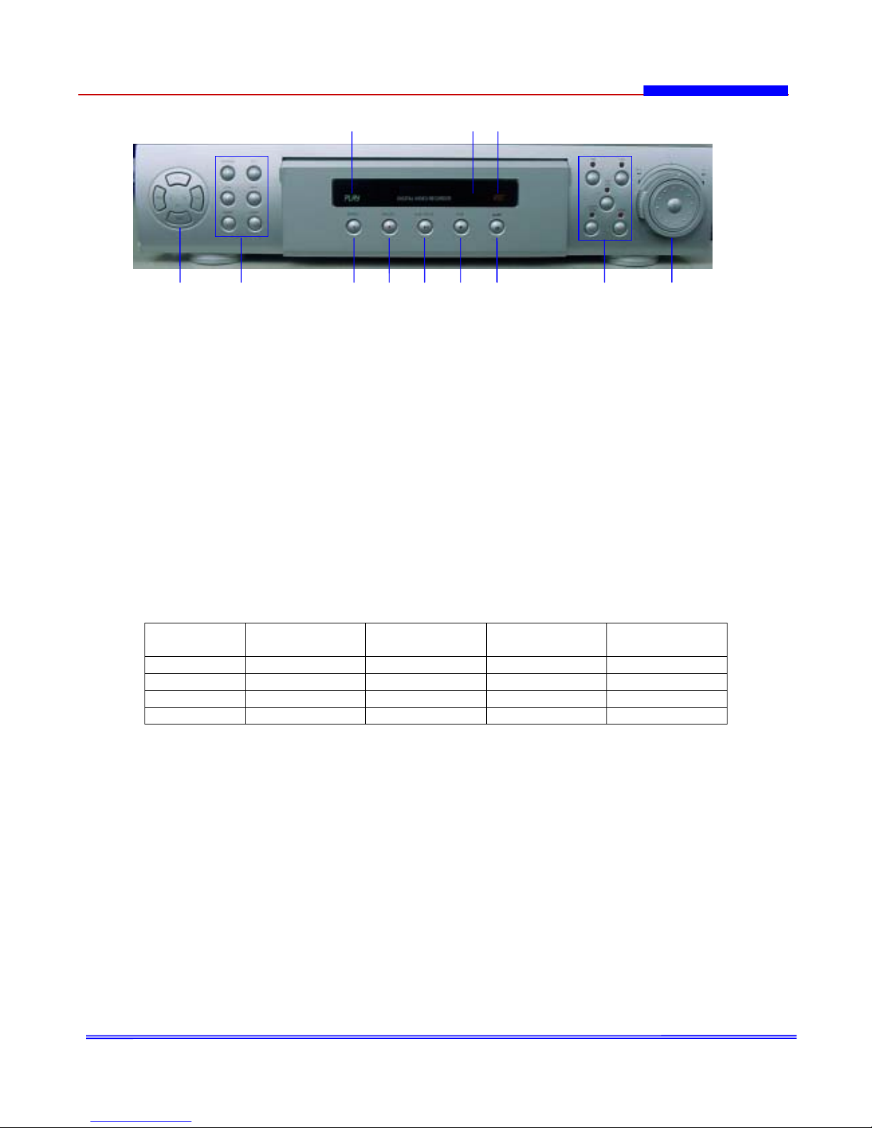
3. Front Panel Controls
Figure 1-1. Front Panel Controls
1. Camera number buttons/Move buttons
Camera number buttons
CH-1,CH-2,CH-3,CH-4 : Full screen for each channel
Press the number of the camera you want to display on the monitor.
Move buttons
(Up) : Navigate up through the menu, zoom, play, search and set button.
(Down) : Navigate down through the menu, zoom, play, search and set button.
(Left) : Navigate left through the menu, zoom, play, search and set button.
(Right) : Navigate right through the menu, zoom, play, search and set button.
2. M-Screen button
Press this button to change the variable display mode (Quad,PIP1,PIP2,Sequence PIP) in
Live mode.
Zoom button
Press this button to display the Zoom area Box on the monitor for Live and Display mode.
FREEZE button
Press this button to freeze image on/off in Display Mode
AUTO button
Press this button to auto switching button in Display Mode
Button
Mode Record/display Menu setup Play Search
1CH / ^ FULL CH1 Move UP Zoom CH1 Move UP
2CH / v FULL CH2 Move DOWN Zoom CH2 Move DOWN
3CH / < FULL CH3 Move LEFT Zoom CH3 Move LEFT
4CH / > FULL CH4 Move RIGHT Zoom CH4 Move RIGHT
12 34567 8 9
10 11 12

- 9 -
MENU button
Press this button to display main menu on the monitor.
Main menu include the following list.
(Password Setup, Date/Time Setup, Record Setup, Schedule Setup, Alarm Setup,
Motion Detection, Camera Name, Display Setup, Pan Tilt Setup, Other Conditions,
Information)
ENTER button
Press this button located zoom area box, is used select sub menu for menu change or
operation.
3. SEARCH button
Press this button to display the search list of HDD.
4. RECORD button
Press this button to begin recording. Press again this button to stop recording.
5. PLAY/PAUSE button
Press this button to begin playback or pause recorded image in playback mode.
When pressed during playback mode, a still image is displayed. To return playback,
press this button again.
6. STOP button
Press this button to stop playback.
7. SLOW button
Press this button to display slow playback mode.
Slow playback mode : 2, 3, 4, 5, 6, 7, 8, 9, 10
8. Pan/Tilt/Zoom Camera Control buttons
PAN button
Press this button to control pan of Pan/Tilt/Zoom Camera or Speed Dome Camera.
TILT button
Press this button to control tilt of Pan/Tilt/Zoom Camera or Speed Dome Camera.
PAN AUTO button
Press this button to control panning automatically of Pan/Tilt/Zoom Camera or Speed
Dome Camera.
CAMERA ZOOM button
Press this button to control zoom of Pan/Tilt/Zoom Camera or Speed Dome Camera.
FOCUS button
Press this button to control focus of Pan/Tilt/Zoom Camera or Speed Dome Camera.

- 10 -
9. Jog/Shuttle
JOG dial
Use the dial to search hard disk drive sector number. (1 unit)
SHUTTLE ring
Use the ring to adjust the playback speed, and to rewind or forward the image, and to
control pan, tilt, zoom, pan auto, focus of Pan/Tilt/Zoom Camera or Speed Dome Camera.
Use the ring to search hard disk drive sector number. (50 or 100 unit)
10. PLAY indicator
Indicates playback mode.
11. Infrared Port
This infrared port received signal of wireless remote control.
12. REC indicator
Indicates recording mode.

- 11 -
4. Rear Panel Controls
Figure 1-2. Rear Panel Controls
1. ALARM IN/OUT terminal
These are input and output terminals for alarm signals.
2. VIDEO out connector (RCA)
This is an RCA output connector for a video signal.
3. MONITOR out connector (RCA)
This is an RCA output connector for a video signal.
4. VIDEO OUT connector (BNC)
These are BNC output connectors for cameras.
5. RS-485 terminal
This terminal can be connected for control of Pan/Tilt/Zoom Camera or
Speed Dome Camera.
6. Power switch
7. AUDIO OUT connector
This is an RCA output connector for an audio signal.
8. AUDIO IN connector
This is an RCA input connector for an audio signal.
9. VIDEO IN connector
These are BNC input connectors for cameras.
10. AC power inlet
The power for this DVR system is for 100~240VAC power cord.
1
810
23 4 5 6
7 9

- 12 -
5. Remote Controller
Figure 1-3. Remote Controller
1. Rec: Record Button 12. M-Screen: Multi-Screen Button
2. Mute: Audio Off button on Record [Change the display mode
3. Zoom: Zoom button Quad->PIP1->PIP2->Seq PIP]
for Live and Play Mode 13. Auto: Auto Switching button
4. Menu: Main Menu in Display Mode
5. Search: To display search list of HDD 14. Freeze: Freeze picture button
6. Up button in Display Mode
7. Left button 15. Enter button: To enter sub menu
8. Down button 16.~19. CH1,CH2,CH3,CH4:
9. Pan-Auto button Full screen for each
10. Pan: Pan control button 20. Right button
[Right/Left] 21. Play/Pause button : Play or pause
11.Tilt : Tilt control button recorded video in play mode
[Up/Down] 22. Stop: Stop button to stop the play mode
23. Slow: Slow button in play mode
[2,3,4,5,6,7,8,9,10]
24. Zoom: Camera Zoom control button
25. Focus: Camera Focus control button
Rec ○
1
Mute ○
2
Search ○
5
Left()○
7
Up ○
6
Down ○
8
Pan-Auto ○
9
Pan ○
10
Tilt ○
11
Auto
Freeze
Ch3
Play/Pause(II)
Right()
Slow
Stop
Zoom
Focus
○
13
○
14
○
19
○
20
○
21
○
23
○
22
○
24
○
25
M-Screen
○
12
Enter
○
15
Ch1
○
16
Ch2
○
17
Zoom ○
3
Menu ○
4
Ch4
○
18
#9~11,24,25 for P/T/Z Camera or
Speed Dome Camera Control Button

- 13 -
System Setup
Turn on the power switch, DVR system will be worked. And the user have to set up the
system of several conditions depend on user environments.
1. Menu Structure
Press MENU button and the main menu will be displayed on monitor.
Figure 2-1. Main Menu
<MAIN MENU List>
!Password Setup : Setting the user password.
!Date/Time Setup : Setting the current date and time.
!Record Setup : Setting the record speed, video quality and resolution.
!Schedule Setup : Setting the normal recording time.
!Alarm Setup : Setting the alarm conditions[Alarm record time].
!Motion Detection : Setting the motion detection condition[Motion record time].
!Camera Name : Setting each camera name.
!Display Setup : Setting the display type of live mode[PIP1, PIP2, Sequence PIP].
!Pan/Tilt Setup : Select protocol of Pan/Tilt/Zoom Camera or Speed Dome Camera.
!Other Conditions : Switching time, Camera Name display, HDD Overwrite.......
!Information : HDD Size, HDD Remain Time, System Information.
. SYSTEM PROGRAMING

- 14 -
2. Password Setup
Set up the password to protect data of established MENU.
If password select set up “ON”, press the main MENU button, then, you will see the
displaying message “Enter Password”. You will be able to enter in screen of main MENU if
you put the established password.
To set the Password, press the MENU button to display the Menu
1. Use the direction button [(Up), (Down)] to select the Password Setup.
2. Press the ENTER button to display the Password Setup menu on the monitor.
Figure 2-2. Password Setup
3. To set the password, use the direction button [(Up), (Down)]to select the
PW Input.
- To select the character, use the direction button [(Left), (Right)].
- To change each characters, use the direction button [(Up), (Down)].
- Press the ENTER button to confirm the selection.
4. To set the password protection, use the direction button [(Up), (Down)]to select the
PW Select.
- To select ON or OFF, use the direction button [(Left), (Right)].
- Press the ENTER button to confirm the selection.
If you set ON of PW Select, Password Protection will be worked.
[Change ‘PW Select’, OFF "ON "OFF by pressing ‘Right’ button.
Press the ENTER button to confirm the selection.
5. Press the MENU button to exit the programming mode.

- 15 -
3. Date/Time Setup
To set the current Date/Time, press the MENU button to display the Menu.
- Use the direction button [(Up), (Down)] to select the Date/Time Setup.
- Press the ENTER button to display the Date/Time Setup menu on the monitor.
Figure 2-3. Date/Time Setup
1. To set the year, use the direction button [(Up), (Down)] to select the YEAR.
- To change the year, use the direction button [(Left), (Right)].
2. To set the month, use the direction button [(Up), (Down)] to select the MONTH.
- To change the month, use the direction button [(Left), (Right)].
3. To set the date, use the direction button [(Up), (Down)] to select the DATE.
- To change the date, use the direction button [(Left), (Right)].
4. To set the hours, use the direction button [(Up), (Down)] to select the HOUR.
- To change the hours, use the direction button [(Left), (Right)].
5. To set the minutes, use the direction button [(Up), (Down)] to select the MIN.
- To change the minutes, use the direction button [(Left), (Right)]..
6. To set the seconds, use the direction button [(Up), (Down)] to select the SEC.
- To change the seconds, use the direction button [(Left), (Right)].
7. To set the week, use the direction button [(Up), (Down)] to select the WEEK.
- To change the week, use the direction button [(Left), (Right)].
8. To set the date format, use the direction button [(Up), (Down)] to select
the Display.
- To change the date format, use the direction button [(Left), (Right)].
The display will be changed by press ‘Right’ button.
Date format : Y(Year)/M(Month)/D(Date) , M/Y/D, D/M/Y
9. Press the MENU button to exit the programming mode.

- 16 -
4. Record Setup
To set the record condition, press the MENU button to display the Menu.
- Use the direction button [(Up), (Down)] to select the Record Setup.
- Press the ENTER button to display the Record Setup menu on the monitor.
Figure 2-4. Record Setup
1. To set the recording speed, use the direction button [(Up), (Down)] to select
the Rec Speed.
- To change the recording speed, use the direction button [(Left), (Right)].
Recording Speed : User can select the recording speed(unit : frame/sec).
NTSC : 30, 28, 26, 22, 18, 16, 14, 12, 10, 8, 6, 4, 2, 1, 1f/2sec, 1frame/4sec
PAL : 25, 23, 21, 19, 17, 15, 13, 11, 9, 7, 5, 3, 1, 1f/2sec, 1frame/4sec
[In case of Alarm & Motion record, it will be recorded 30fps for duration time.]
2. To set the recording video quality, use the direction button [(Up), (Down)] to
select the Video Qual.
- To change the recording video quality, use the direction button [(Left), (Right)].
Recording Video Quality : These are 3 levels in Recording Video Quality.
[Super/High/Low]
User can change it by pressing ‘Right’ button.
3. To set the recording video resolution, use the direction button [(Up), (Down)] to
select the Video Res..
- To change the recording video resolution, use the direction button [(Left), (Right)].
Recording Video Resolution : These are 2 levels of Recording Video Resolution.
Full : 720*480(NTSC), 720*576(PAL)
Half : 360*480(NTSC), 360*576(PAL)
4. To set the buzzer on or off, use the direction button [(Up), (Down)] to select
the Buzzer.
- To change the buzzer on or off, use the direction button [(Left), (Right)].
Record Buzzer : If you select ‘ON’, DVR System makes buzzer sound
when it record video.
5. To set the pre recording, use the direction button [(Up), (Down)] to select the
Pre Rec.
- To change the pre recording on or off, use the direction button [(Left), (Right)].
Pre Rec (Pre Record) : This DVR system will record pictures which are captured prior to
event picture like detection of Alarm and Motion. And Pre record is real time
recording even though the record setup is not real time
(NTSC:30frame/sec, PAL:25frame/sec).
Pre recording time : OFF, 5s, 10s, 15s, 20s, 25s, 30s
If Pre Rec set time, even though user press the Search button, search list doesn’t
display on the monitor. When the Pre Rec is working, the DVR System is checking HDD
continuously.
6. Press the MENU button to exit the programming mode.

- 17 -
5. Schedule Setup
User can set schedule time so that DVR can record at that time period.
To set the schedule recording condition, press the MENU button to display the Menu.
- Use the direction button [(Up), (Down)] to select the Schedule Setup.
- Press the ENTER button to display the Schedule Setup menu on the monitor.
Figure 2-5. Schedule Setup
1. To set the schedule recording, use the direction button [(Up), (Down)] to select
a day of week.
2. Press the ENTER button to select the day.
3. To move the start time(hour, minutes), use the direction button [(Left), (Right)].
4. To set the start time(hour, minutes), use the direction button [(Up), (Down)].
5. To move the stop time(hour, minutes), use the direction button [(Left), (Right)].
6. To set the stop time(hour, minutes), use the direction button [(Up), (Down)].
7. To set the schedule recording on or off, use the direction button [(Left), (Right)]
to move ON or OFF position.
8. To select the schedule recording on or off, use the direction button [(Up), (Down)].
9. Press the ENTER button to confirm the selection.
10. Repeat step 1 to 9 to set schedule recordings for other days of the week.
11. Press the MENU button to exit the programming mode.

- 18 -
6. Alarm Setup
To set the record condition, press the MENU button to display the Menu.
- Use the direction button [(Up), (Down)] to select the Alarm Setup.
- Press the ENTER button to display the Alarm Setup menu on the monitor.
Figure 2-6. Alarm Setup
*Alarm In : This DVR system are 4ch of sensor[Alarm1 ~ Alarm4] input ports in rear side
of DVR. If user use the external sensor with DVR System, have to select the
type of sensor[High(NC)/Low(NO)] and ‘ON’, otherwise select ‘OFF’. [DVR
receive High Level Signal in Normal Status]
*Alarm Out : Also, DVR has 1ch of out port which give a signal to work external equipment.
[light, door lock. Siren…]
1. To set the alarm mode for camera 1, use the direction button [(Up), (Down)] to
select the Alarm1.
- To change the alarm mode, use the direction button [(Left), (Right)].
Alarm mode : OFF, L/ON, H/ON
2. To set the alarm mode for camera 2, use the direction button [(Up), (Down)] to
select the Alarm2.
- To change the alarm mode, use the direction button [(Left), (Right)].
Alarm mode : OFF, L/ON, H/ON
3. To set the alarm mode for camera 3, use the direction button [(Up), (Down)] to
select the Alarm3.
- To change the alarm mode, use the direction button [(Left), (Right)].
Alarm mode : OFF, L/ON, H/ON
4. To set the alarm mode for camera 4, use the direction button [(Up), (Down)] to
select the Alarm4.
- To change the alarm mode, use the direction button [(Left), (Right)].
Alarm mode : OFF, L/ON, H/ON
5. To set the alarm out, use the direction button [(Up), (Down)] to select the
Alarm Out.
- To change the alarm out mode, use the direction button [(Left), (Right)].
Alarm out mode : ON, OFF
6. To set the alarm recording time, use the direction button [(Up), (Down)] to select
the Rec Time.
- To change the alarm recording time, use the direction button [(Left), (Right)].
Alarm Recording Time : 2S, 5S, 10S, 30S, 1M, 2M, 3M, 5M, 10M, 30M
7. Press the MENU button to exit the programming mode

- 19 -
7. Motion Detection
To set the motion detection, press the MENU button to display the Menu.
- Use the direction button [(Up), (Down)] to select the Motion Detection.
- Press the ENTER button to display the Motion Detection menu on the monitor.
This DVR has ‘Motion Detection’ function, DVR recognize the video movement
automatically.
Figure 2-7. Motion Detection
1. To set the motion detection function, use the direction button [(Up), (Down)] to
select the Detect.
- To change the motion detection function mode on or off, use the direction button
[(Left), (Right)].
2. To set the recording duration time after detected motion, use the direction button
[(Up), (Down)] to select the Rec Time.
- To change the motion detection recording time, use the direction button
[(Left), (Right)].
Motion Detection Recording Time : 2S, 5S, 10S, 30S, 1M, 2M, 3M, 5M, 10M, 30M
3. To set the sensitivity of motion detection, use the direction button [(Up), (Down)]
to select the Sensitivity.
- To change the sensitivity of motion detection, use the direction button
[(Left), (Right)].
Sensitivity : 10%, 20%, 30%, 40%, 50%, 60%, 70%, 80%, 90%, 100%
4. To set the motion detection of channel 1 area, use the direction button
[(Up), (Down)] to select the CH1 Detect.
- To select on or off, use the direction button [(Left), (Right)]
5. To set the motion detection of channel 2 area, use the direction button
[(Up), (Down)] to select the CH2 Detect.
- To select on or off, use the direction button [(Left), (Right)]
6. To set the motion detection of channel 3 area, use the direction button
[(Up), (Down)] to select the CH3 Detect.
- To select on or off, use the direction button [(Left), (Right)]
7. To set the motion detection of channel 4 area, use the direction button
[(Up), (Down)] to select the CH4 Detect.
- To select on or off, use the direction button [(Left), (Right)]
8. Press the MENU button to exit the programming mode

- 20 -
8. Camera Name
To set the camera name, press the MENU button to display the Menu.
- Use the direction button [(Up), (Down)] to select the Camera Name.
- Press the ENTER button to display the Camera Name menu on the monitor.
User can insert the Camera Name(6characters) on the Monitor for display.
Figure 2-8. Camera Name
1. To set the camera name of Camera 1, use the direction button [(Up), (Down)] to
select the CH 1.
- Press the ENTER button to select CH 1.
- To select the position of character, use the direction button [(Left), (Right)].
- To change each characters, use the direction button [(Up), (Down)].
- Press the ENTER button to confirm the selection.
2. Repeat step 1 to set others camera name.
3. Press the MENU button to exit the programming mode.
Table of contents
Other CiA DVR manuals


