CiA TVV424S User manual

TVV424S
4 channels digital videorecorder
User Manual

2
Table of Contents
1. Introduction
1-1 Safety Warning …………………………………………………………………………………
1-2 Features ………………………………………………………………………………………….
1-3 Specifications …………………………………………………………………………………...
2. Installation
2-1 Package contents ……………………………………………………………………………….
2-2 Connection ………………………………………………………………………………….….
2-3 Rack mount installation …………………………………………………………….…………..
2-4 RS232 /RS485 Remote protocol ……………………………………………………………..…
3. Configuration
3-1 Install HDD …………………………………………………………………………………….…
3-2 Front panel keypad ……………………………………………………………………………..
3-3 Back panel connection ………………………………………………………………………….
3-4 Menu setup ……………………………………………………………………………………….
3-5 System setup …………………………………………………………………………………….
3-6 TIMER setup (Schedule Time-Lapse record mode setup)……………………………..…....
3-7 Camera setup……………………………………………………………………………..…….…
3-8 Record Setup …………………………………………………..………………………….…. ..
3-9 Alarm Setup…………...……………………………………………………………………….….
3-10 Dwell setup ……………..…………..…………………………………………………….…
3-11 Remote Setup ………………………………………………………………………….…..
3-12 Event ………………………………………………………………………………………………
4. Operation
4-1 Power on …………………………………………………………………………………………
4-2 Recording ………………………………………………………………………………………...
4-3 Camera Select (1-4) ………... ……………………………………………………………….….
4-4 Quad……. ………………………………………………………………………………………...
4-5 Play ………….………..…………………………..……………………………………………...
4-6 Key Lock ………………………………………………………………………………………………
5. Trouble shooting & appendix
5-1 Trouble shooting …………………………………………………………………………………
5-2 Compatible HDD brands …………………………………………………………………...…...
1. Introduction
Thank you for choosing this high quality Digital Quad Recorder. The DQR converts analog NTSC
or PAL video to digital images and records them to a removable hard disk drive. Digitally recorded
video has many advantages compared to analog video recorded on tape. There is no need to
adjust tracking. Digital video can be indexed by time schedule or events, and you can instantly
view video after selecting the time or event. You can freeze frames, fast-forward, and fast-
reverse, slow forward, and slow reverse without image streaking or tearing. It can be used as a
replacement for both a time-lapse VCR and a Quad in a security installation.
3
4
5
6
6
7
8
9
11
13
17
17
22
24
25
27
29
32
34
36
36
37
37
38
38
39
40

3
1.1 Safety Warning
All the safety and operating instructions should be read before the operation. The improper
operation may cause permanent damage.
1.1.1 Please use the adaptor provided from AV TECH.
1.1.2 Please lift and place this equipment gently.
1.1.3 Do not expose this equipment to open sunlight.
1.1.4 Do not use this equipment near water or in contact with water.
1.1.5 Do not spill liquid of any kind on the equipment.
1.1.6 Please power down the unit before unplugging.
1.1.7 This equipment should be operated only with power source from standard package.
1.1.8 Unauthorized repair or parts substitutions may result in fire, electric shock or other
hazards.
1.1.9 Do not switch the Power On & Off within short period o time (within 3 seconds).
1.1.10 Do not attempt to service this equipment by yourself. Refer all servicing and repair to
qualified service personnel.
1.1.11 This unit should be operated only from power source indicated on the manufacturer’s
label.
1.1.12 Installation should be made by a qualified service personnel and should conform to all
local safety codes and regulations.
1.2 Features
1.2.1 Wavelet Compression Format replaces Time-Lapse VCR and Quad
1.2.2 4 Audio inputs / 2 Audio outputs
1.2.3 On Screen Display and RTC (Real time clock) Function
1.2.4 Resolution
Screen Modes Resolution
Full screen 704(H) x 468(V) <NTSC> / 704(H) x 564(V) <PAL>
4 channels 352(H) x 234(V) <NTSC> / 352(H) x 282(V) <PAL>
1.2.5 Main monitor output allows simultaneous viewing of 4 cameras and full screen viewing.
1.2.6 Multi Screen Display Mode
zBelow display modes are selectable for in surveillance & DQR playback mode:

4
1.2.7 Digital Zoom can be up to 2 X 2 in DQR playback modes
1.2.8 4 channels and each channel has independent title generator (up to 10 characters).
1.2.9 Video Quality Adjustable on Each Channel
1.2.10 Alarm Input & Output Function
z4 channels alarm input, ALARM display and one alarm output.
zVideo loss detection on each channel.
zRecord 160 events.
1.2.11 Power-loss memory function: set up parameter will remain, in case of power failure.
1.2.12 Support 1 Removable HDD, IDE Type
1.2.13 Timer: Schedule recording
1.2.14 Display refresh rate up to 60 IPS (50 IPS for PAL)
1.2.15 Record refresh rate up to 60 IPS (50 IPS for PAL)
1.2.16 Quick Multiple Search by date/time, alarm, full list
1.2.17 Fast and slow playback in multiple speeds.
1.2.18 Security password protection
1.2.19 RS-232, RS-485 communication protocol
1.3 Specifications
Video format NTSC/EIA or PAL/CCIR
Hard disk storage IDE type, UTMA 66 above, 1 removable HDD supported
Record mode Manual / Alarm / Timer
Camera Input Signal Composite video signal 1 Vp-p 75ΩBNC, 9 channels
Camera Loop Back Composite video signal 1 Vp-p 75ΩBNC, 9 channels
Main Monitor Output Composite video signal 1 Vp-p 75ΩBNC
Motion Detect Area 15 * 12 targets per camera (NTSC) / 15 * 14 targets per camera (PAL)
Audio input 4 audio inputs, (RCA)

5
Audio output 2 audio outputs, (RCA)
Motion Detect Sensitivity 256 Levels
Video Loss Detection Yes
Refresh Rate 60 images/sec. for NTSC / 50 images/sec. for PAL
Recording Rate 60 images/sec. for NTSC / 50 images/sec. for PAL
Dwell Time Programmable (1~10 Sec)
Key Lock Yes
Picture Zoom 2 x 2
Camera Title 8
Video Adjustable Color/Contrast/Brightness Adjustable
Alarm Input TTL input, Hi (5V), Low (GND)
Alarm Output COM,/N.O/N.C.
Remote Control RS-232 or RS-485
Time Display Format YY/MM/DD, DD/MM/YY, MM/DD/YY, OFF
Power Source AC90~240V+ 10% switching adaptor
Power Consumption <27W
Operation Temperature 10 ~ 40
℃
RS-232C / RS-485 (bps) 115200
、
57600
、
19200
、
9600
、
4800
、
3600
、
2400
、
1200
Dimension 380 x 270 x 65mm (W x L x H)
Net Weight 5.2Kgs
Specifications are subject to change without notice.
2. Installation
2.1 Package contents
The package contents the following items.
zDigital Quad Recorder
zHDD cartridge
zKey for cartridge (Attached in HDD cartridge)
zPower cord
zUser manual
zRack mounting kit (Optional)
2.2 Connection
2.2.1 Connect with cameras

6
Main Monitor
Sensor
Alarm Input
Alarm
PC
RS232
432 1
Video Camera
Video Output
Video Input
Audio Input
Audio Output
2.3 Rack mount installation
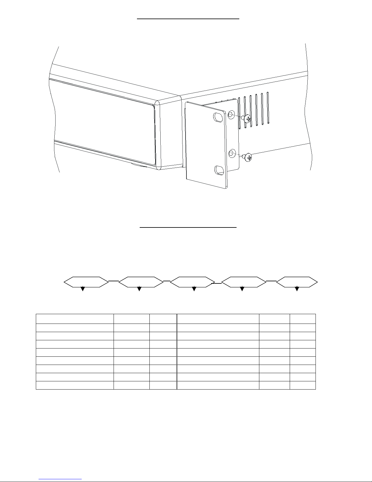
7
Front Angle with Rock Mount
Side View with Rack Mount
2.4 RS232/ RS485 Remote Protocol
You can use the PC keyboard to simulate DQR keypad.
DATA: REMOTE PROTOCOL using 8 bit data、1 start bit、1stop bit
ACT C0H ID FUNCTION STOP
(FFH) (7FH)
FUNCTION CODE ASCII FUNCTION CODE ASCII
Menu 0x4D M Play 0x50 P
Enter 0x0D ENTER REC 0x72 r
Search 0x48 H CH1 0x31 1
Slow 0x53 S CH2 0x32 2
Up 0x55 U CH3 0x33 3
Down 0x4E N CH4 0x34 4
Left 0x4C L QUAD 0x51 Q
Right 0x52 R AUTO 0x41 A

8
3. Configuration
3.1 HDD Installation
3.1.1 Installing Hard Drive into Cartridge
3.1.1.1. Please find the Key in the Cartridge.
3.1.1.2. Use the provided miniature key and insert into the keyhole, turning the key
counter-clockwise.
3.1.1.3. Pull the handle outwards to remove the carrier body away from the cartridge
frame.
3.1.1.4. Push the open button to slide the top cover backwards and remove.
3.1.1.5. Insert the DC power cable and IDE cable on the HDD.
3.1.1.6. Position the HDD into carrier body and secure the HDD with the four 6#-32
screws provided.
3.1.1.7. Slide the top cover back to the carrier body by sliding it forward to secure.
3.1.1.8. Slide the carrier body back into the cartridge frame.
3.1.2 Function Settings and Operation
3.1.2.1 Power Indicator and HDD Access indicator
When power is ON, the indicator will display the following message:
3.1.3 Key lock
Status
Segment
Power
status Security status
Item Indicator
Power Indicator Green LED
HDD Access Indicator Yellow LED

9
A ON Locked (Irremovable)
B OFF Unlocked (Removable)
You must turn key lock to “ A ” position before powering on the unit. Otherwise HDD will
not operate properly.
3.1.4 The Record Time differs on Record Speed and Record Quality. Please Refer to the
following table.
NTSC SYSTEM
IPS 60 30 15 8 4 2 1
Best 12hr 24hr 48hr 90hr 180hr 360hr 720hr
High 15hr 30hr 60hr 112.5hr 225hr 450hr 900hr
Normal 24hr 48hr 96hr 180hr 360hr 720hr 1440hr
Record
Quality
Basic 40hr 80hr 160hr 300hr 600hr 1200hr 2400hr
HDD Type 120GB
PAL SYSTEM
IPS 50 25 12 6 3 2 1
Best 12hr 24hr 50hr 101hr 203hr 304hr 608hr
High 15hr 30hr 63hr 127hr 253hr 380hr 760hr
Normal 24hr 49hr 101hr 203hr 405hr 608hr 1220hr
Record
Quality
Basic 41hr 81hr 168hr 338hr 675hr 1013hr 2025hr
HDD Type 120GB
Note: Above data is from actual test data obtained from recording normal TV program.
(Reference only)

10
3.2 Front panel keypad
MENU SEARCH
ENTER SLOW
Full
HDD TIMERALARM PLAY
FF
Right
REW
Left
QUAD
AUTO
STOP / Down
REC
REC AUTO
PAUSE / Up
POWER
Please follow the instructions below to operate this unit.
1. Install HDD :This unit is with a removable hard disk drive tray. Before turning on this device, you
must install hard disk drive (not included in standard package) for proper operation.
2. MENU :Press MENU to enter main menu operation mode, and press Administrator Password
(default:0000) to access main menu.
3. ENTER :Press ENTER for confirmation.
4. SEARCH
Press SEARCH for period recording video searching.
5. SLOW : To press SLOW to slow down speed of play mode.
6. STOP / Down :
STOP : Under DQR Record/Play mode, it will stop recording / playing.
DOWN : Under setup mode , it can work as DOWN button.
7. REC :Press REC to start recording.
8. POWER : To power on, press power button.
To power off, press power button again.
9. REW / Left :
REW :Under DQR play mode, it can play video backward at high speed, and press REW again
to adjust speed at 1, 2, 4, 8, 16, 32 times
LEFT: Under setup mode , it can work as LEFT button.
10.FF / Right :

11
FF : Under DQR play mode, it can play video forward at high speed, and press FF again to
adjust speed at 1, 2, 4, 8, 16, 32 times.
Right : Under setup mode , it can work as RIGHT button.
11.PAUSE / Up :
PAUSE : Under DQR play mode, it will make video pause.
UP : Under setup mode , it can work as UP button.
12.PLAY :Press PLAY to play recorded video.
13.LED Light : Under the following conditions, the LED Light is ON.
(1) HDD Full:HDD is full
(2) ALARM:When Alarm Enable : Yes (when alarm is triggered, the led is flashing)
(3) TIMER:When Timer Enable : Yes
(4) PLAY:Play operation
(5) REC:Recording operation
(6) AUTO: 4 channel will display in full screen by turns
14. : Displays the CH1 camera in the full screen format.
: Displays the CH2 camera in the full screen format.
: Displays the CH3 camera in the full screen format.
: Displays the CH4 camera in the full screen format.
QUAD :Display 4 cameras in quad screen format.
AUTO : 4 channel will display in full screen format by turns.
3.3 Back panel connection

12
POWER
VIDEO 1 2 3 4
2
MONITOR
1
4 L
OUT
IN
3 R
EXTERNAL I/O
WARNING : TO REDUCE THE RISK OF ELECTRIC SHOCK,
DO NOT RE MOVE COVER (OR B ACK).
NO USER-SERVICEABLE PARTS INSIDE.
REFER SERVICING TO QUAL IFIED
SERVICE PERSONNEL.
RISK OF ELECTRIC SHOCK
DO NOT OPEN
1. POWER INPUT
Connect to power cord (standard package attached).
2. VIDEO IN 1~4
Connect to video source, such as camera.
3. MONITOR
Connect to Main monitor
4. AUDIO IN 1~4
Connect to audio source, such as microphone.
* IPS should be set over 30 (for NTSC) or 25 (for PAL)
AUDIO OUT R/L
Connect to monitor or speaker.
5. External I/O
Controlled remotely by an external device or control system.
Alarm input, external I/O explanation.
3.3.9 External I/O
25 pin com port

13
9 pin com port
PIN 1. RS232-TX : RS-232
DQR can be controlled remotely by an external device or control system, such as a
control keyboard, using RS-232 serial communications signals.
PIN 2. RS232-RX : RS-232
DQR can be controlled remotely by an external device or control system, such as a
control keyboard, using RS-232 serial communications signals.
DQR

14
PIN 3. ALARM INPUT 1 (INPUT)
To connect wire from ALARM INPUT 1 ( PIN 3 ) to GND ( PIN 9 ) connector, DQR will
start recording and buzzer will be on. When alarm has been triggered, signal becomes
“Low”, and it will stop all alarm activities. Under normal operation, signal remains
“High”.
PIN 4. ALARM INPUT 2 (INPUT)
To connect wire from ALARM INPUT 2 ( PIN 4 ) to GND ( PIN 9 ) connector, DQR will
start recording and buzzer will be on. When alarm has been triggered, signal becomes
“Low”, and it will stop all alarm activities. Under normal operation, signal remains
“High”.
PIN 5. ALARM INPUT 3 (INPUT)
To connect wire from ALARM INPUT 3 ( PIN 5 ) to GND ( PIN 9 ) connector, DQR will
start recording and buzzer will be on. When alarm has been triggered, signal becomes
“Low”, and it will stop all alarm activities. Under normal operation, signal remains
“High”.
PIN 6. ALARM INPUT 4 (INPUT)
To connect wire from ALARM INPUT 4 ( PIN 6 ) to GND ( PIN 9 ) connector, DQR will
start recording and buzzer will be on. When alarm has been triggered, signal becomes
“Low”, and it will stop all alarm activities. Under normal operation, signal remains
“High”.
PIN 7. EXTERNAL ALARM NC
Under normal operation COM connect with NC and disconnect with NO. But when
alarm triggered, COM disconnect with NC, and connect with NO.
PIN 8. EXTERNAL ALARM NO
Under normal operation COM connect with NC and disconnect with NO. But when
Alarm triggered, COM disconnect with NC, and connect with NO.
PIN 9. GND
GROUND
PIN 10. RS485-B
DQR can be controlled remotely by an external device or control system, such as a control
keyboard, using RS485 serial communications signals.
PIN 11. RS485-A
DQR can be controlled remotely by an external device or control system, such as a
control keyboard, using RS485 serial communications signals.

15
PIN 12. DISK FULL (OUTPUT)
When HDD is full, it sends a signal to trigger next DQR record mode, if you install
another DQR. Under normal operation, the signal remains “High”. But when disk full,
DVR will send the “Low” signal.
PIN 13. REC START (INPUT)
This pin can accept the external trigger signal to activate record mode from external
device. When the external signal turn to “Low”, it will trigger DQR record mode. When
the external signal back to “High”, it will stop recording action.
The default normal operation remains “High”.
PIN 14. ALARM RESET (INPUT)
To connect wire from ALARM RESET ( PIN 14 ) to GND ( PIN 9 ) connector, it can
disable ALARM. An external signal to ALARM RESET ( PIN 14 ) can be used to reset
both ALARM OUTPUT signal and DQR’s internal buzzer. When alarm has been
triggered, signal becomes “Low”, and it will stop all alarm activities. Under normal
operation, signal remains “High”.
PIN 15. EXTERNAL ALARM COM
Under normal operation COM connect with NC and disconnect with NO. But when
alarm triggered, COM disconnect with NC, and connect with NO.
3.4 Menu setup

16
Press ”MENU” to enter main menu. You will
need to enter password to access main menu.
To press “Right” “Left” to move digit, and Press
”Up” “Down” to select number. Press ”ENTER”
button to confirm password.
Ex.: Password : 0000 (Default : 0000)
PASSWORD : 0000
After keying in correct password, confirm by
pressing ”ENTER” button, screen will show
following options.
TIMER -------- Scheduling Record
CAMERA ------- Camera Channel Setup
RECORD------- Record Mode Setup
ALARM -------- Alarm Mode Setup
DWELL -------- Auto channel switching setup
REMOTE------- Remote control protocol Setup
SYSTEM ------- System Setup
EVENT -------- Event List
(MENU)
►TIMER
CAMERA
RECORD
ALARM
DWELL
REMOTE
SYSTEM
EVENT
*For the unit can be operated properly, we start introducing from System setup.
3.5 System setup
Press ”MENU” to enter main menu. You will
need to enter password to access main menu.
Press “Right” “Left” to move digit, and Press
”Up” “Down” to select number. Press ”ENTER”
button to confirm password.
Ex.: PASSWORD : 0000 (Default : 0000)
PASSWORD : 0000

17
After keying the correct password, confirm by
pressing ”ENTER” button, screen will show
following options.
TIMER -------- Scheduling Record
CAMERA ------- Camera Channel Setup
RECORD------- Record Mode Setup
ALARM -------- Alarm Mode Setup
DWELL -------- Auto channel switching setup
REMOTE------- Remote control protocol Setup
SYSTEM ------- System Setup
EVENT -------- Event List
(MENU)
►TIMER
CAMERA
RECORD
ALARM
DWELL
REMOTE
SYSTEM
EVENT
Press ”Up” “Down” to choose SYSTEM setup
TIMER
CAMERA
RECORD
ALARM
DWELL
REMOTE
►SYSTEM
EVENT
(MENU)
TIMER
CAMERA
RECORD
ALARM
DWELL
REMOTE
►SYSTEM
EVENT
Press ”ENTER”to confirm SYSTEM setup, and the screen will show following options.
(SYSTEM)
►AUDIO INPUT : 1
BUZZER : ON
HDD OVERWRITE : NO
MESSAGE LATCH : NO
DATE DISPLAY : Y-M-D
DATE : 2003-JAN-02 (THU)
TIME : 01:41:54
NEW PASSWORD : XXXX
CLEARD HDD : NO
SYSTEM RESET : NO
3.5.1 AUDIO INPUT setup:
This device allows user to set the AUDIO INPUT. User can choose one of 4
channels to record at one time.
3.5.1.1 Press ”Up” “Down” to choose AUDIO INPUT :

18
3.5.1.2 Press ”ENTER” button to confirm AUDIO INPUT
3.5.1.3 Press ”Up” “Down” to choose the AUDIO INPUT : 1~4
3.5.1.4 Press ”MENU”to exit and confirm current operation.
3.5.1.5 Press ”MENU” again to exit and close AUDIO INPUT setup mode.
3.5.2 BUZZER setup:
This device allows user to set the BUZZER. BUZZER will be trigged by event occurrence
when the setting is ON.
3.5.2.1 Press ” Up” or “ Down” to choose BUZZER
3.5.2.2 Press ” ENTER” button to confirm BUZZER
3.5.2.3 Press ” Up” or “ Down” to choose the BUZZER : ON/OFF
ON: Internal Buzzer ON
OFF: Internal Buzzer OFF
3.5.2.4 Press ” MENU”to exit and confirm current operation.
3.5.2.5 Press ” MENU ” again to exit and close BUZZER setup mode.
3.5.3 HDD OVERWRITE Setup option:
This device allows user to set the HDD OVERWRITE.
3.5.4.1 Press ” Up” or “ Down” to choose HDD OVERWRITE
3.5.4.2 Press ” ENTER” to confirm HDD OVERWRITE setup.
3.5.4.3 Press ” Up” or “Down” to choose HDD OVERWRITE setup
NO : When HDD full will stop recording
YES : When HDD full will overwrite the HDD recording
3.5.4.4 Press ” MENU”to exit and confirm current operation.
3.5.4.5 Press ” MENU” again to exit and close HDD OVERWRITE setup mode.
3.5.4 MESSAGE LATCH setup
This device allows user to decide the External Alarm graph showed on monitor or not.
3.5.4.1 Press ” Up” or “ Down” to choose MESSAGE LATCH setup
3.5.4.2 Press ” ENTER” button to confirm MESSAGE LATCH setup
3.5.4.3 Press ” Up” or “ Down”to choose the MESSAGE LATCH: YES/NO
YES : Message latch ON
NO : Message latch OFF
3.5.4.4 Press ” MENU”to exit and confirm current operation.
3.5.4.5 Press ” MENU” again to exit and close MESSAGE LATCH setup mode.

19
3.5.5 DATE DISPLAY setup
This device allows user to set the title shown on monitor or not.
3.5.5.1 Press ” Up” or “ Down ” to choose DATE DISPLAY setup
3.5.5.2 Press ” ENTER” button to confirm DATE DISPLAY setup
3.5.5.3 Press ” Up” or “ Down ” to choose DATE DISPLAY format
Y-M-D / M-D-Y / D-M-Y / OFF
3.5.5.4 Press ” MENU ” to exit and confirm current operation.
3.5.5.5 Press ” MENU ” again to exit and close DATE DISPLAY setup mode.
3.5.6 DATE setup
This device allows user to set date on monitor.
3.5.6.1 Press ” Up ” or “ Down ” to choose DATE display
3.5.6.2 Press ” ENTER ” to confirm DATE setup.
3.5.6.2 Press ” Up ” or “ Down ” to choose the correct Date, and press press “ Right ” or
“ Left ” to move digit location.
3.5.6.4 Press ” MENU ” to exit and confirm current operation.
3.5.6.5 Press ” MENU ” again to exit and close DATE setup mode.
3.5.7 TIME setup:
This device allows user to set time on monitor.
3.5.7.1 Press ” Up ” or “ Down ” to choose TIME display
3.5.7.2 Press ” ENTER ” to confirm TIME display.
3.5.7.3 Press ” Up ” or “ Down ” to choose the correct Time, and press press “ Right ” or “
Left ” to move digit location.
3.5.7.4 Press ” MENU ” to exit and confirm current operation.
3.5.7.5 Press ” MENU ” again to exit and close TIME setup mode.
3.5.8 NEW PASSWORD: XXXX setup: (Default password: 0000)
This device allows user to set the new password.
3.5.8.1 Press ” Up ” or “ Down ” to choose NEW PASSWORD: XXXX setup.
3.5.8.2 Press ” ENTER ” to confirm NEW PASSWORD: XXXX setup.
3.5.8.3 Press ” Up ” or “ Down ” to choose number, and press“ Right ” or “ Left ” to move
digit location.
3.5.8.4 Press ” MENU ” to exit and confirm current operation.
3.5.8.5 Press ” MENU ” again to exit and close NEW PASSWORD setup mode.
3.5.9 CLEAR HDD setup

20
This device allows user to have the HDD cleared.
3.5.9.1 Press ” Up ” or “ Down ” to choose CLEAR HDD setup.
3.5.9.2 Press ” ENTER ” to confirm CLEAR HDD setup.
3.5.9.3 Press ” Up ” or “ Down ” to choose CLEAR HDD setup YES or NO.
YES: Confirm to clear HDD, and screen will show followings.
ALL DATA IN HDD
WILL BE CLEARED
ARE YOU SURE?
(◄: NO ►: YES )
Press“ ►” to clear HDD
NO: Confirm not to clear HDD.
3.5.9.4 Press ” MENU ” to exit and confirm current operation.
3.5.9.5 Press ” MENU ” again to exit and close CLEAR HDD setup mode.
3.5.10 SYSTEM RESET setup
This device allows user to reset the system.
3.5.10.1 Press ” Up ” or “ Down ” to choose SYSTEM RESET setup.
3.5.10.2 Press ” ENTER” to confirm SYSTEM RESET setup.
3.5.10.3 Press ” ” Up ” or “ Down ” to choose SYSTEM RESET Yes or No
YES: To confirm System Reset (load default system reset)
NO: Confirm not to System Reset
3.5.10.4 Press ” MENU ” to exit and confirm current operation.
3.5.10.5 Press ” MENU ” again to exit and close SYSTEM RESET setup mode.
3.6 TIMER setup (Schedule Time-Lapse record mode setup)
Table of contents
Other CiA DVR manuals


