EN - 4
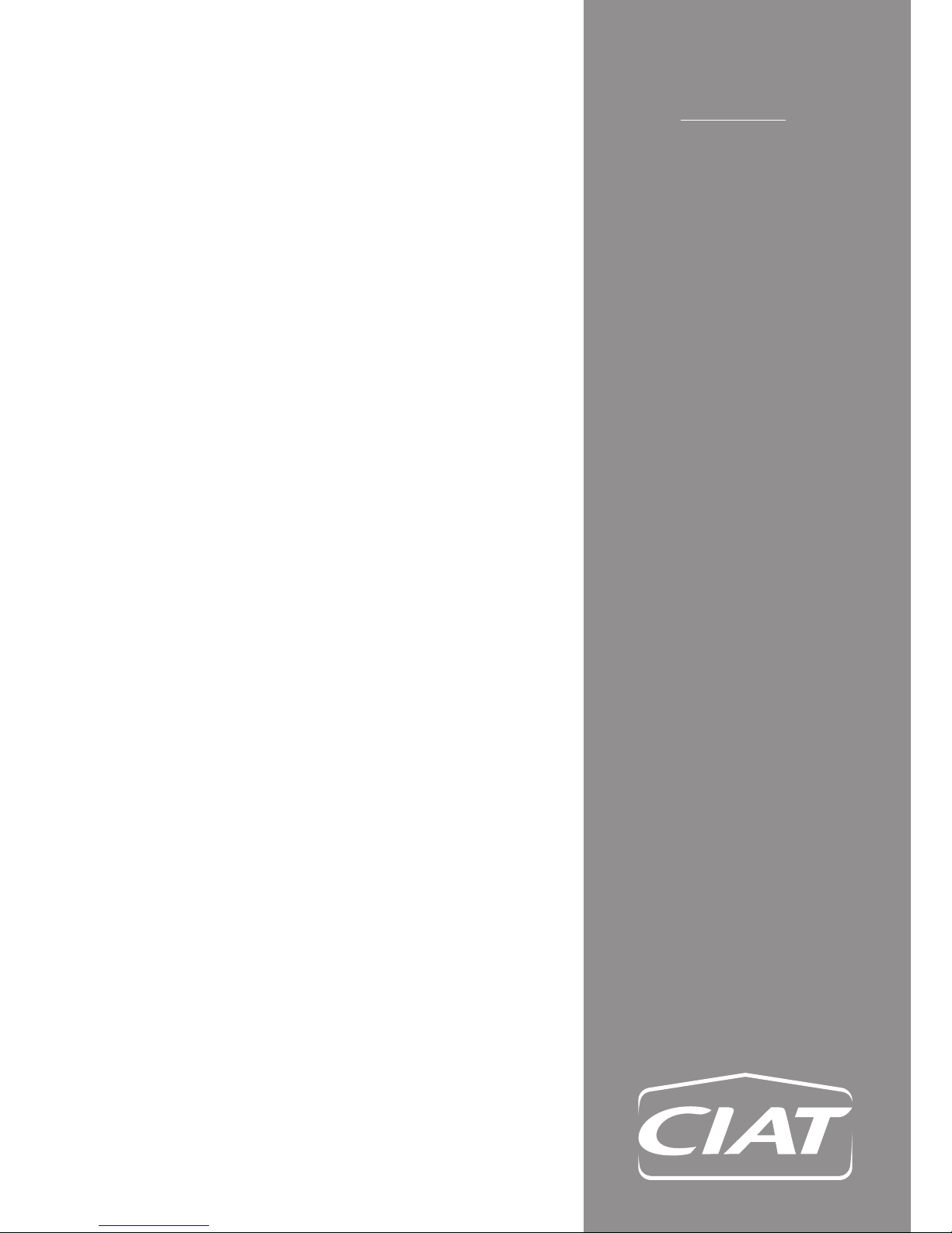
1.2.4 Identifying the equipment
A legible and indelible data plate listing the specifications of the
unit is affixed in a visible location on the unit.
This information (particularly the description and the serial
number) must be quoted in all correspondence.
The HP MAX value: PSM indicated on the name plate is the
maximum operating pressure (= 42 bar)
This value corresponds to the activation pressure for the safety
device: the HP pressure switch. A burst test on a representative
model is carried out periodically in accordance with standard
EN 378-2. The burst pressure must be at least 3 times the
operating pressure, i.e. 3 x 42 bar = 126 bar.
1.2.5 Handling
Units on pallets must be transported using a pallet truck.
Warning: the machine must be moved using a suitable means
of transport. The heat pump must not be dragged along the
ground directly on its rubber feet, as this may damage the
adjustment system.
Wear suitable gloves when handling the unit.
1.2.6 Installation
CIAT units must only be installed by experienced, qualified
personnel with the necessary electrical and hydraulic
accreditation. The installing company must provide the
equipment manager with a declaration of conformity in
accordance with current standards and the indications supplied
by CIAT in this manual. The recommendations and instructions
given in the maintenance brochures and the special instructions
on the labels must be followed.
Always comply with applicable standards and regulations.
CIAT accepts no contractual or non-contractual liability for
damage caused to persons, animals or property due to
installation, maintenance or servicing errors or misuse.
This instruction manual and the user manual form an integral
part of the unit, and must therefore be kept safe and ALWAYS
handed over if the unit is transferred to a new owner or another
system. If a manual is damaged or lost, you can order a new
1.3 Basic safety rules
To prevent the risk of accidents during installation,
system start-up and adjustment, it is essential to
remember that a heat pump contains a pressurised
refrigeration circuit and refrigerant, as well as electrical
voltage and fluid at a temperature up to 150°C (risk of burns
from touching the pipes)
Note that certain basic safety rules apply to the use of this type
of unit:
• Before carrying out any work on the equipment, ensure
that the supply voltage is switched off (and the capacitors
discharged). Any electrical discharge carries a risk of injury.
• The unit must not be used by unsupervised people with
disabilities or children.
• It is forbidden to touch the unit in bare feet or if any part of the
body is wet or damp.
• It is forbidden to modify the safety or adjustment devices
without authorisation and instructions from the device
manufacturer.
• For work on the machine during or shortly after operation,
wear gloves suitable for high temperatures and electrically
insulated tools.
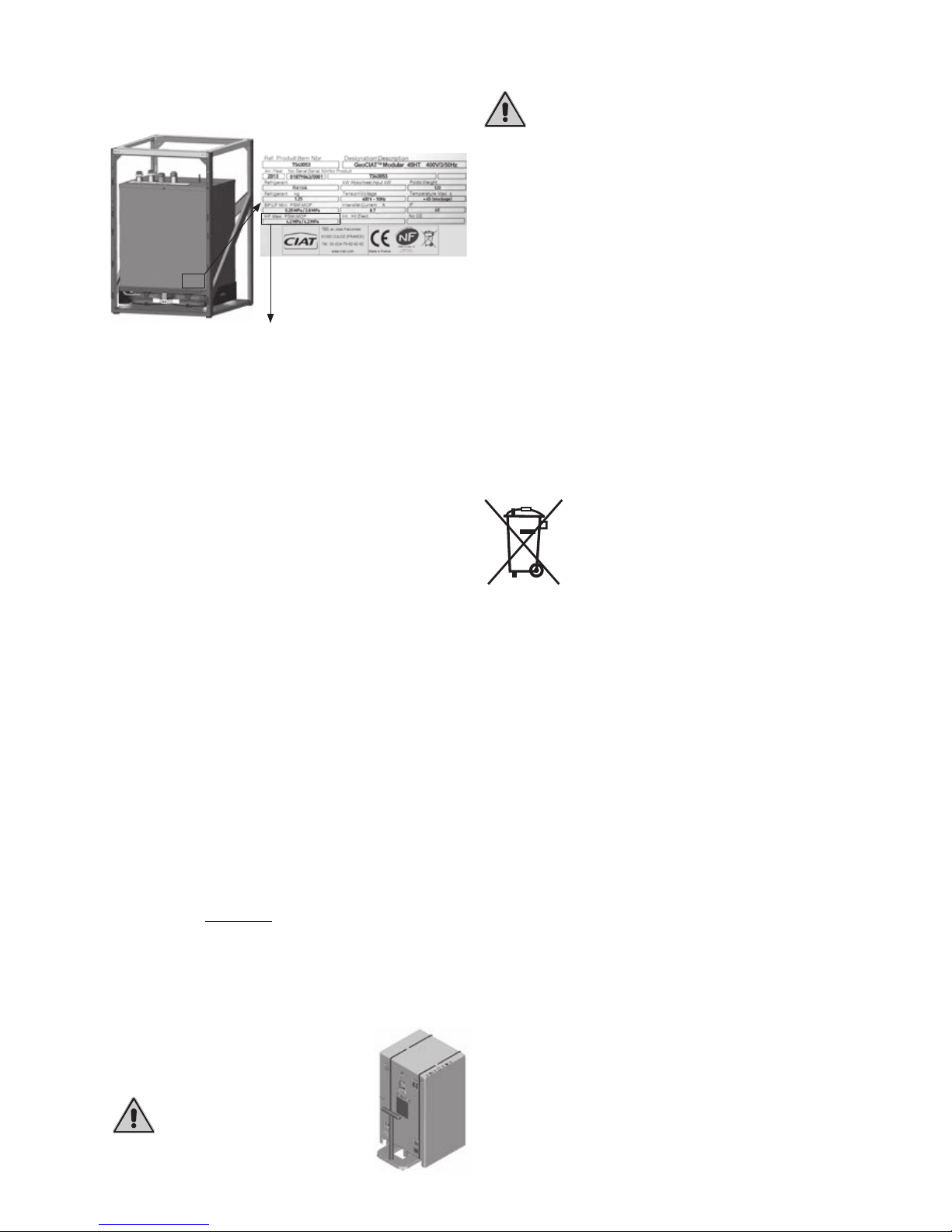
1.4 Waste disposal by users in private waste
facilities within the European Union
This symbol indicates that the product and its packaging
must not be disposed of in ordinary household
waste or in the natural environment. It is your
responsibility to ensure your waste is taken
to a designated recycling point for electrical
and electronic devices. Separating your waste
for recycling during disposal helps protect the
environment and safeguard health.
To find your nearest recycling centre, contact your local council
or waste disposal service.
The units are not stackable.