Pennsylvania 7600E User manual

Pennsylvania Scale Co.
1042 New Holland Ave.
Lancaster PA 17601
800-233-0473
www.pascale.com
INSTRUCTION & SERVICE MANUAL
7600E Digital Indicator
V2.84

2
TABLE OF CONTENTS
SPECIFICATIONS………………………………………3
INSTALLATION…………………………………………4
SETUP ACCESS………………………………………..5
MENU LAYOUT...………………………………………6
CONFIGURATION……………………………………..7
REMOTE SERIAL DISPLAY………………………….8
CALIBRATION………………………………………….9
SERIAL PORTS………………………………………10
SERIAL COMMUNICATIONS……………………….11
ANALOG OUTPUT……………………………………13
DIGITAL INPUT/OUTPUT……………………………15
SETPOINTS……………………………………………16
OVER/UNDER…………………………………………17
BATCH MODE…………………………………………18
SERIAL COM. SETPOINT/ACC……………………...19
TIME & DATE………………………………………….20
WEIGH IN/OUT………………………………………..21
SMART SERIAL……………………………………….23
ASCII CHART………………………………………….28
DISPLAY MESSAGES………………………………..32
115/220 VAC…………………………………………..33
SPARE PARTS………………………………………..34

3
SPECIFICATIONS
Smart Serial Setup: 8 custom print files plus 8 macro files, 30 characters each.
Batch Start/Stop: Control from front panel or remote input.
Setpoint Operation: 4 output relays configurable for normal setpoints, over/under or
manual/auto batch modes.
LOAD CELL A/D CONVERTER
TYPE: 24 bit delta sigma
EXCITATION: 5 VDC, 120 mA max.
SIGNAL INPUT: 16 mv
SENSITIVITY: 0.1 uV/grad
UPDATE RATE: 30 update/second
DISPLAY: Six (6) Decades, 0.6 inch LED
KEYPAD: Full numeric plus controls
POWER INPUT: 117/217 VAC, 50-60 HZ, 20 watts, fuse 0.25 A Slo-Blow.
SERIAL PORTS:
Port 1: RS232C or 20ma
Port 2: RS485, RS232C or 20mA.
ENCLOSURE: Stainless Steel, NEMA 4x, Tilt - Stand Base, 7lbs.
CASE: 9” (w) x 6.44” (h) x 4” (d) Tilt or panel mount.
OPTIONS:
TIME & DATE: 12/24 hr, battery backed.
ANALOG OUTPUT: 0-10v, 4-20ma (16 bit D/A).
DIO: 4 AC/DC – inputs, 4 AC outputs (SS Relays, 0.5 amp)
Optional Case: 10” (w) x 6.5” (h) x 4” (d) Tilt only.
Panel Mount: Kit (replaces tilt stand).

INSTALLATION
POWER WIRING: The indicator is designed to be operated from 117/217 VAC, 50-60 Hz. The
unit power cord must be plugged into a grounded 3 - wire polarized AC wall socket. All normal
wiring and grounding precautions should be observed, including use of a "clean" AC power
line.
SCALE WIRING:The unit is equipped with cable gland entry for load cell cable insertion and
internal (pluggable) terminal strip for 4 / 6 wire connection. Remove sense jumpers P11-8/7,
P11-6/5 for six wire.
4
Transformer F1
Line
Filter
Shielded
A/D Converter
6 5 4 3 2 1 TB-1
8 7 6 5 P11
Signal +
Signal -
Excitation +
Sense +
Excitation –
Sense -
P12 0.25A
SB
A
J1 SW4
B P5
CAL
EW-1000 Rev…..
1 2

SETUP ACCESS
To access instrument configuration, calibration or to enable options, depress the “Zero” key for
five seconds.
The Audit Trail counters (“Pxxxx” and “Cxxxx”) are displayed first followed by access code
request (“AC?”). The initial factory setting is “0000” which can be entered with four steps of the
“Gross/Net” key (“AC0000”) and “Print”. If no entry is made, instrument returns to operate
mode.
The access code can be changed to any four digit combination during setup exit when display
again shows “AC?”.
The “Check” key provides the software version “V 1.XX” followed by the display test routine.
Use the “ENT” key to advance to the keyboard test and to exit tests.
After entry, use the “Tare Recall” key to select a main menu; configuration (“SEL.CFG”),
calibration (“SEL.CAL”), or options (“SEL.OPX”) and “Start/Stop” to back step.
The “Gross/Net” key enters selected menu and is used to step through sub categories.
Individual parameter selection is made with the “Tare/Recall” key, which then steps through
the parameter choices (“Zero” key back steps within the menu).
The “ENT” key is used at any point to “back” up from categories to menus and to “save?” and
“AC?” and exit.
During the exit steps, if changes were made, the display is “save?” with alternate “no”. To save
changes, use the “Units” key to select “yes” and “ENT” to exit.
Calibration numeric entries are entered directly followed with the “ENT” key.
5
Front panel access is inhibited if conventional “sealing” is applied by
setting jumper J1-1 in the B position. The board mounted “CAL” button is
then used for access.

Menu Layout
6
Totalizer
Smart Serial
CFG
CAL
OP1
OP2
OP3
OP4
Configuration: Divisions, count by, decimal, over
range, filter, AZM, zero range, ISM, lb/kg, serial port
selection, DIO enable
Calibration: Zero, Span
Analog Output: Gross, Net, Display; Zero, Span, Trim
Setpoint DIO: Setpoint, Over/Under, Manual / Auto Batch
Time & Date: 24 hr, 12 hr, Print format
Weigh – In / Weigh – Out: Truck mode
OP5 10 Point Linearity, Filter selection
OP6
OP7
OP8
AC/DC Battery

7
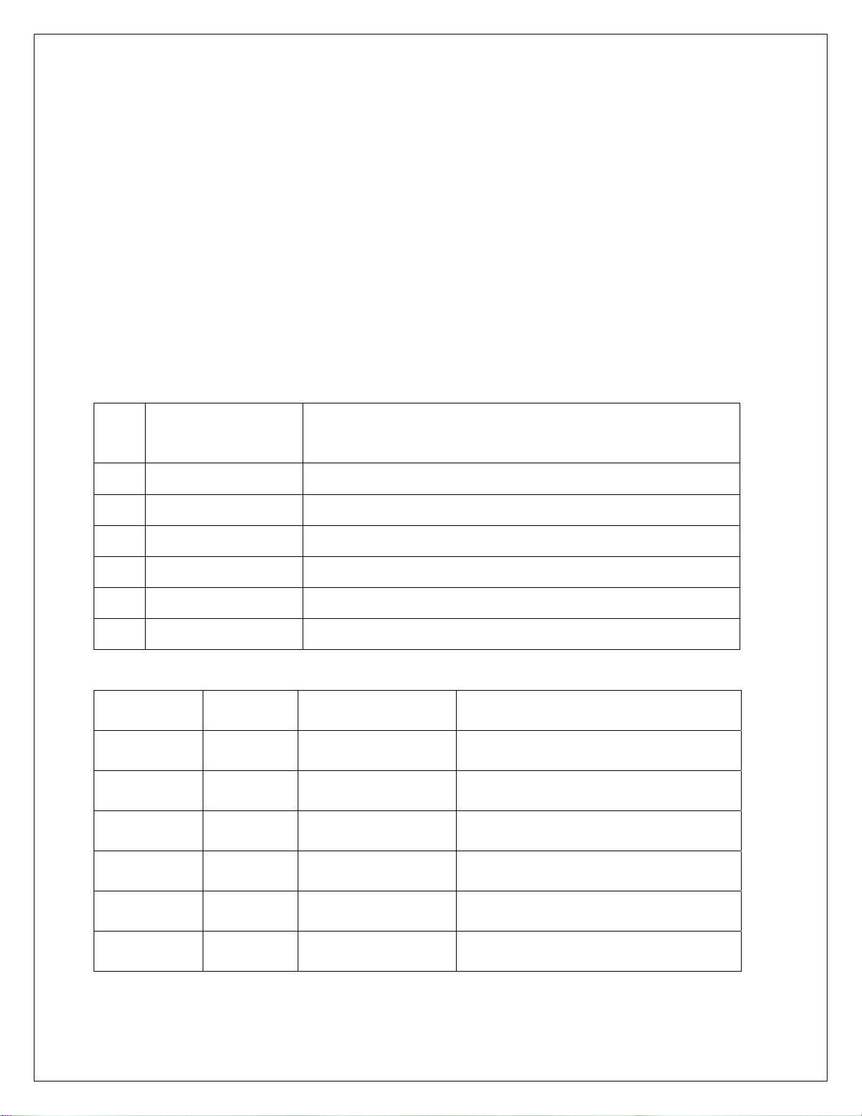
CONFIGURATION: “SEL.CFG” Use Gross/Net to enter the menu and step to each category,
Tare Recall to select parameters. ENT to return to menu selection.
Capacity is the combination of “1”, “2” and “3”.
Example: 1__100, 2___2 and 3__0.0 = 2,000 x 0.2 lb
Step Parameters Definition
1 5, 10, 15, 20…100, 120…1000 Number of divisions x100
100 = 10,000 divisions
2 1, 2, 5, 10, 20, 50, and 100. Count by selection
10,000 divisions, count by 2 = 20,000
3 0, 0.0, 0.00, 0.000, and 0.0000 Decimal point selection
4 105P, 9 d (105% or 9 divisions) Overrange selection
5 1, 2, 3, 4, 5, 6, 8, 10, 12, 15……90 Digital filter selection (averaging)
6 off, 0.5, 1, 3, 5, 10 (divisions) Auto Zero Maintenance (AZM)
7 1.9, 5, 10, 20, FS (% of capacity) Zero range selection
1.9% of 2,000 x 0.2 = 38.0 lb
7.1 off, on (ISM) Zero’s scale on power-up
8 off, 1, 3, 5,10 (divisions) Motion Band selection
9 lb, kg, con Units selection and convert
10 nt, Gtn, n.nt, n.Gtn.
Port 1 serial output selection
nt display only, Gtn is Gross Tare Net
and n.nt/n.Gtn inhibit negative gross
printing
11 off, co, de Off, Continuous, or Demand
12 7o, 7E, 8n 7- odd, 7- even or 8- none
13 12, 24, 48, 96 Baud rate selection
14 off, 1, 2, 3, 5, 10, 15 (seconds) Delay between lines or continuous
output.
19 A, b A : adds “STX” in continuous
b : No “STX” in continuous
20 nt, Gtn, n.nt, n.Gtn Port 2 serial output selection
21 off, co, de, Ln Off, Continuous, Demand, Network
22 7o, 7E, 8n 7- odd, 7- even or 8- none
23 12, 24, 48, 96 Baud rate selection
24 off, 1, 2, 3, 5, 10, 15 (seconds) Delay between lines or continuous
output.
25 1 – 16 (RS485/RS422) Network address selection
30 off, on DIO Inputs

8
Remote Serial Display (RSD) Option
In RSD mode the instrument can be set to work with another unit as a “remote” either as the
main or the slave unit. Communication is pre-set for channel two only on both units.
(RS232, 9600, 8, none)
When in remote mode, re-access to the following selections requires using the internal “cal”
switch.
Remote unit can have full or partial control of the main unit. Devices are available to replace
the cable for wireless communication.
40 rd.OF,
rd.En,
rd.re
rd.En : Selects Indicator as Remote Display (RSD)
rd.re : Allows indicator to operate w/RSD
41 En.On Allow remote keypad operation
42 Zr.On Enable/Disable zero key
43 tr.On Enable/Disable tare key
44 Un.On Enable/Disable unit key
45 Print function with parameter “11” see below
46 Fn.On Enable/Disable all other functions
11.P1.xx 45.Pr.xx RSD Serial Port 1 RSD Print Key
off off Disabled Disabled
off on Disabled Sends print cmd to weigh meter
co off Sends co serial Disabled
co on Sends co serial Sends print cmd to weigh meter
dE off Disabled Disabled
dE on See right…..
Outputs demand format from
RSD serial port 1

9
CALIBRATION: “SEL.CAL” Use Gross/Net to enter the menu indicated by a flashing “C” on
the left and live weight is displayed. Scale zero (dead load) or adjusting span (single or multi-
point) are independent. Therefore either can be done and repeated as necessary before
exciting calibration. If an error has been made, exit without “storing” will return to prior setup.
KEY (FUNCTION) DISPLAY Definition
(Live weight 123 lb) “C”__123 Cal mode scale reading
Zero (acquire dead load) “------“ to “C___0.0” acquires new dead load
(live weight 5000 lb) “C”__4995 Scale reading with load
Enter numeric value directly:
(Adjustment complete) 005000 adjusted value
Then ENT:
(adjust span) “------“ to “C” 5000 displays new span
Repeat as required then ENT to exit CAL
“Save ?” “No” or “Save ?” “Yes” use Units to select and ENT to store “yes” with changes or
“no” to exit without changes.
Continue with ENT to “Ent AC” which allows access code change by entering a new four digit
code and ENT or ENT with no entry to maintain current password.
Option 5 Ten point calibration: Allows up to 10 span points (pt1…….pt10). Zeroing the scale
clears the existing values. Points are assigned incrementally with error indication if the addition
is not above the prior point or exceeding scale capacity.
Filter selection included for rolling or box averaging.
5.1 OFF, On Enable 10 point span
5.2 A, b A : Rolling average
B : Box average

SERIAL PORTS
Port 1: RS232 duplex (Rx,Tx), 20ma (Tx).
Port 2: RS232 duplex (Rx,Tx), 20ma (Rx,Tx), RS485, or RS422.
Note: Position jumper on J2 for Port 2 receive selection.
10
1
2
3
4
5
6
7
8
9
10
11
12
13
14
15
GND
Tx1, RS232
Rx1, RS232
Tx2, RS232
Rx2, RS232
Tx1, -20ma
Tx1,Tx2,+20ma (5 vdc)
Tx2, -20ma
Rx2,+20ma
Rx2, -20ma
B, RS485, RS422-Tx
A, RS485, RS422-Tx
B, RS422-Rx
A, RS422-Rx
GND
Rx2
A-RS232
B-20ma
C-RS485
D-RS422
J2
EW-1000 Rev…
O1

11
Serial Communications
Remote Commands
<Z><cr> Zero Scale “Gross” mode, no motion, inside zero range.
<N><cr> Switch to Net “Gross” mode with Tare stored.
<G><cr> Switch to Gross “Net” mode.
<T><cr> Auto Tare Switch to Net, no motion, not at “Gross” zero.
<P><cr> Print Valid display, No motion
<U><cr> Units Change units
Data Formats
Demand Mode: <stx><pol><DATA><sp><lb/kg><sp><GR/NT><cr/lf>
Continuous Mode: <stx><pol><DATA><L/K><G/N><status><cr/lf>
Brackets “<>” are not sent
stx: “Start of Text” character (ASCII 002) (can be removed in continuous: config 19)
pol: Polarity sign, “SPACE” (ASCII 032) for positive or (-) sign (ASCII 045) for negative
sp: Space character (ASCII 032)
DATA: Seven (7) digit data field including decimal point or fixed (dummy) zero if selected.
“Leading Zero Suppression” with leading zeros transmitted as “space” characters.
lb/kg: Two (2) character field data identification for weight units, in demand (printer) mode.
Weight in lb = “lb” (ASCII 108,098), weight in kg = “kg” (ASCII 107,103)
L/K: One (1) character field data identification for weight units in continuous (computer)
mode.
Weight in lb = “L” (ASCII 076), weight in kg = “K” (ASCII 075)
GR/NT: Two (2) character field data identification for weighing mode in demand (printer)
mode.
Gross Mode = “GR” (ASCII 071,082), Net Mode = “NT” (ASCII 078,084)

12
G/N: One (1) character field data identification for weighing mode in continuous
(computer) mode.
Gross Mode = “G” (ASCII 071), Net Mode = “N” (ASCII 078)
status: One (1) character data identification used in the continuous (computer) output
mode to identify the status of the indicator. Characters are listed below in order of priority.
Calibration/configuration <D> (ASCII 068)
Over/Under Range <O> (ASCII 079)
Motion <M> (ASCII 077)
Center of Zero <C> (ASCII 067)
None of the above <sp>(ASCII 032)
cr/lf: Two (2) character field, “Carriage Return” (ASCII 013), “Line Feed” (ASCII 010)
Guidelines for Serial Output:
Demand format will inhibit “print” when scale is in “motion” or with negative “Gross” weight, even
in “Net” mode (based on setting “CFG 10”).
Local Network Protocol:
Command to the indicator:
<*><DD><00><cmd><data entry><CR>
Response from indicator:
<:><00><DD><cmd echoed><data resp><CR>
Where: (<,> brackets not sent)
* = Message from master (2AH)
DD = Indicators address
00 = Master address (fixed at 00)
CR = Message terminator (ODH)
: = Response from indicator (3AH)
cmd = Command to indicator
cmd ech = Command echoed from indicator
data ent = Data entered into indicator
data resp = Data response from indicator

OPTION 1: Analog Output
0 – 10 Vdc or 4 – 20 ma, select with jumpers J1 and J2
Transformer F1
Line
Filter
6 5 4 3 2 1 TB-1
8 7 6 5 P11
P12
0.25A
SB
EW-1000-AOUT
EW-1000 Rev…..
A
J1
B
1 2
1 2
- +
TB 20
V
I
J1 J2 V
I
- +
0 – 10 Vdc or 4 – 20 ma
Position J1 & J2 for V/I
P5
13

14
Option 1 Analog Output: “SEL.OP1” Use Gross/Net to enter the menu and step to
each category, Tare Recall to select parameters. ENT to return to menu selection.
DISPLAY Parameters Definition
1.1__Gr Gr, Net, DSP Analog tracks gross, net or display
“1.5__Zr” “000” (flashes current analog starting point)
Adjust value and ENT to adjust starting point.
“1.6__FS” “500” (flashes current analog span point)
Adjust value and ENT to adjust full scale.
1.7__ZrA While monitoring the output, use Start/Stop to decrease, Tare Recall to
increase the analog reading (Zero trim digi-pot).
1.8__FSA While monitoring the output, use Start/Stop to decrease, Tare Recall to
increase the analog reading (Span Trim digi-pot).
ENT to exit OP1.

15
OPTIONS 2: DIO
AC Inputs; D1, D2 are not installed, J1 = short (underside), J2 = open, R1 – R4 = 18k
(3w, 5%, flame proof).
DC Inputs; D1, D2 are installed, J1 = open (cut trace), J2 = short, R1 – R4 = 1.5k (1/2w,
5%, carbon film). AC Outputs; Solid State Relays, 120VAC, 0.5A.
.
Option 2 DIO: “SEL.OP2” First select the operating mode for “Setpoint”, “Over/Under”,
“Manual or Auto Batch”. After setup, the parameters for the selection are entered from
EW-1000 Rev…
P4
TB 30
1
2
3
4
5
6
TB 31
1
2
3
4
5
6
7
8
EW-1000-DIO
COM J1
COM
IN 1
IN 2
IN 3
IN 4 J2
D1
D2
K1 OUT 1
K2 OUT 2
K3 OUT 3
K4 OUT 4

16
the weighing mode.
Use Gross/Net to enter the menu and step to each category, Tare Recall to select
parameters. ENT to return to menu selection.
Note: external Inputs are enabled in Configuration with “CFG 30”.
DIO Inputs can be configured for 120vac, 5vdc or dry contact.
Normal Batch
CFG 30 off
Batch
IN 1 Gross/Net Stop n/a
IN 2 Tare Start n/a
IN 3 Zero Zero Bypass
Ing 1
IN 4 Print Print Bypass
Ing 2
DIO Outputs are 120vac (0.5 amp) or optional 24 vdc, based on operating mode:
Dual Setpt 1 Setpt 2 Ov/Un Man B Auto B
Out 1 Setpt1-A Main 1 Main 1 Low Main 1 Main 1
Out 2 Setpt1-B Fast F1 Fast F1 Accept Fast F1 Fast F1
Out 3 Setpt2-A Tol Main 2 High Main 2 Main 2
Out 4 Setpt2-B Zero B Fast F2 Zero Zero Fast F2
Checkweigher “Bar” graph legends:
Ck1-3 Out Low Low Accept High Out High
Setpoint values are entered from “Weighing Mode” by the SET key and direct numeric
entry.
Weight errors of any kind (e.g., ol, ul, etc) will de-energize all relay outputs and abort a
batch if one is in progress.
Four outputs are available to use as two setpoints with main and fast feed, single
setpoint main and fast feed plus tolerance and zero band. Also Pre-Act can be applied
to the main, for material in-flight compensation.
Step Parameter Definition

17
2.0 OFF, SP, OU.UN, bAt1, bAt2 Mode select: setpoint, over/under (check
weighing), Manual Batch, Auto Batch
2.0 SP Setpoint
2.2 Off, s1, s1.p, s1.d, s.p.d, Dual Setpoint. 1 + pre-act, + drib, + both, Set1-A&B.
2.3 Gr, nt, dSP, Count Setpoint 1 tracks Gross, Net, Display, Count
2.4 POS, ZER Output on below reading (POS), inverted (ZER)
2.6 Off, s2, s2.p, s2.d, s2.p.d, tOL,
Dual Setpoint. 2 + pre-act, + dribble, + both,
Tolerance, Set2-A&B.
2.7 Gr, nt, dSP, Count Setpoint. 2 + pre-act, + dribble, + both
2.8 POS, ZER Output on below reading (POS), inverted (ZER)
2.10 ZbO Zero band output (input weight value)
2.11 Off, On Hysteresis, provides 3 grads to prevent relay
chatter
s.p.d
example
SP1.trG (Target) = 1000
SP1.PrE (Pre-act) = 5
SP1.drb (Dribble) = 10
Main and Fast Feed are on until reading reaches
990, then Fast Feed turns off and Main continues
until Pre-act at 995
2.0 OU.UN Over/Under – check weighing
2.2 Off, HL, tGt, Ck1, Ck2, Ck3 High/Low band, Target and +/- band, Check
Weigher 1-3.
2.3 Gr, net, dSP Outputs track Gross, Net, Display
2.4 POS, ZER Invert low
2.5 POS, ZER Invert accept
2.6 POS, ZER Invert high
2.10 ZbO Zero band output (input weight value)
2.11 Off, On Hysteresis, provides 3 grads to prevent relay
chatter
2.12 Off, On Enables “Bar” graph legends
HL
example Low = 950
High = 1050 Then low is on until 950, then accept is on until
1050 and high is on above 1050.
tGt
example
Target = 1000
Low = 50
High = 50 Outputs match above example for HL
Note: Batch printouts are from Port 1
only

18
2.0 Bat 1 Manual Batch mode, pauses between setpoints
2.1 Prn, tAr, dln
7400 uses print, tare or external (DIO) for start.
Pressing any key other than “start” will pause and
a second push will abort. 7600E uses Start/Stop
panel switch
2.2 Off, s1, s1.p, s1.d, s.p.d Setpoint. 1 + pre-act, + dribble, + both
2.3 Gr, nt, dSP, Count Setpoint 1 tracks Gross, Net, Display, Count
2.4 POS, ZER Output on below reading (POS), inverted (ZER)
2.6 Off, s2, s2.p, s2.d, s2.p.d Setpoint. 2 + pre-act, + dribble, + both
2.7 Gr, nt, dSP, Count Setpoint. 2 + pre-act, + dribble, + both
2.8 POS, ZER Output on below reading (POS), inverted (ZER)
2.10 ZbO Zero band output (input weight value), available if
S2 dribble not used
2.0 Bat 2 Auto Batch mode, continues without pause
2.1 Prn, tAr, dln
7400 uses print, tare or external (DIO) for start.
Pressing any key other than “start” will pause and
a second push will abort. 7600E uses Start/Stop
panel switch
2.2 Off, s1, s1.p, s1.d, s.p.d Setpoint. 1 + pre-act, + dribble, + both
2.3 Gr, nt, dSP, Count Setpoint 1 tracks Gross, Net, Display, Count
2.4 POS, ZER Output on below reading (POS), inverted (ZER)
2.5 Off, 1, 2, 3, …., 10 Time Delay (settling) before print
2.6 Off, s2, s2.p, s2.d, s2.p.d Setpoint. 2 + pre-act, + dribble, + both
2.7 Gr, nt, dSP, Count Setpoint. 2 + pre-act, + dribble, + both
2.8 POS, ZER Output on below reading (POS), inverted (ZER)
2.9 Off, 1, 2, 3, …., 10 Time Delay (settling) before print
2.10 ZbO Zero band output (input weight value), available if
S2 dribble not used
Relay override command: <RLY> K(1-4) State (0=off, 1=on)
<RLY><0> Reset, restore to normal operation.
<RLY><3><1> Turn K3 on
<RLY><4><0> turn K4 off
Additional Serial Commands: Setpoint/Accumulator

19
Totalizer/Accumulator reset command. Send TC<CR> to reset the totalizer, and the
meter responds with a TC+<CR><LF> string.
Ten/Nine-digit Accumulator Printing/Serial Format Output
COMMAND Output Description
TR1<CR> “ 57.85 lb” 10/9-digit w/ printable units (e.g., lb or kg)
TR2<CR> “ 57.85LA” 10/9-digit w/ computer units (e.g., L or K) & A for
accumulator.
TR3<CR> “ 57.85” 10/9-digit only
TR4<CR> “0000057.85” 10/9-digit w/ leading zeros
All transmissions are terminated by a CR &LF.
If there is a decimal-point in the accumulator, nine digits are transmitted.
Setpoint Recall:
<S><R><1><CR> Requests value of setpoint 1
<S><R<I><CR><LF> Response if Setpoint 1 is off
<S><R><1><(><SP><SP><1><0><0><0><)><CR><LF> if setpoint = 1000
Setpoint Entry:
<S><E><1><(><1><0><0><0><)><CR>
Full-Duplex Setpoint Parameter Entry/Recall
1 2 3 4 5 6
Setpoint SP-1 SP-2
Setpt-Preact SP-1 Pr-1 Pr-2
Setpt-Drib SP-1 Dr-1 Dr-2
Stpt-pr-dr SP-1 Pr-1 Dr-1 Pr-2 Dr-2
Stpt-dual SP-1-A SP-1-B SP-2-A SP-2-B
Output K1 K2 K3 K4
OP3 Time & Date
3.1 ---, 24H, 12A, 12P Skip time, 24 hour, 12 hour am, 12 hour pm

20
3.2 T1 Set time: hh mm ss
3.3 dA Set date: mm dd yy
3.4 S.no, no, Let Month print selection, short numerical
(mm/dd/yy), number 01 thru 12, month spelled
out
3.5 Off, Un, Ab, On Print under, above or on the same line
OP4 Weigh – In / Weigh - Out See page 19
OP5 10 Point Linearity On, Off see page 9
OP6 Totalizer
6.1 Off, On, AU Enable Totalizer (operates with Batch or Print)
AU: Auto accumulates/prints stable weight
6.2 Off, 1……50 Totalizer reset band
Option 6 Totalizer: Operates with “print” function in normal mode or batch mode.
In normal mode, current value is added to the totalizer with each “Print” command. The
reset band is used to inhibit a double add when not in Batch Mode.
View the Total with the “2” key and during the display (AC..XXXX), the “Print” key is
used to print the total, the “Ent” key returns to weigh mode.
The “Clear” key is used to clear the totalizer by first changing the message from
“Clr.ACC…no” to “Clr.ACC…yes” with the “Units” key and “Ent” to complete. A
“Cleared” message is provided for conformation.
Note: Totalizer works with port 1 only and the “Print” key is disabled when Batch Mode
and Totalizer are both enabled.
OPTION 4: Weigh – In / Weigh – Out
Truck Scale Application: Provides six digit Identification.
Table of contents
Other Pennsylvania Measuring Instrument manuals