manuals.online logo
Brands
  1. Home
  2. •
  3. Brands
  4. •
  5. CIB UNIGAS
  6. •
  7. Burner
  8. •
  9. CIB UNIGAS PBY1030 Operating manual

CIB UNIGAS PBY1030 Operating manual

MANUAL OF INSTALLATION - USE - MAINTENANCE
PBY1025
PBY1030
PBY1040
M039126CE Rel. 4.304/2017
BURNERS - BRUCIATORI - BRULERS - BRENNER - QUEMADORES -
ГОРЕЛКИ
Progressive, Fully-modulating
Heavy oil Burners
2
DANGERS, WARNINGS AND NOTES OF CAUTION
THIS MANUAL IS SUPPLIED AS AN INTEGRAL AND ESSENTIAL PART OF THE PRODUCT AND MUST BE DELIVERED TO THE
USER.
INFORMATION INCLUDED IN THIS SECTION ARE DEDICATED BOTH TO THE USER AND TO PERSONNEL FOLLOWING
PRODUCT INSTALLATION AND MAINTENANCE.
THE USER WILL FIND FURTHER INFORMATION ABOUT OPERATING AND USE RESTRICTIONS, IN THE SECOND SECTION
OF THIS MANUAL. WE HIGHLY RECOMMEND TO READ IT.
CAREFULLY KEEP THIS MANUAL FOR FUTURE REFERENCE.
1) GENERAL INTRODUCTION
The equipment must be installed in compliance with the regulations in
force, following the manufacturer’s instructions, by qualified personnel.
Qualified personnel means those having technical knowledge in the
field of components for civil or industrial heating systems, sanitary hot
water generation and particularly service centres authorised by the
manufacturer.
Improper installation may cause injury to people and animals, or
damage to property, for which the manufacturer cannot be held liable.
Remove all packaging material and inspect the equipment for integrity.
In case of any doubt, do not use the unit - contact the supplier.
The packaging materials (wooden crate, nails, fastening devices, plastic
bags, foamed polystyrene, etc), should not be left within the reach of chil-
dren, as they may prove harmful.
Before any cleaning or servicing operation, disconnect the unit from
the mains by turning the master switch OFF, and/or through the cut-
out devices that are provided.
Make sure that inlet or exhaust grilles are unobstructed.
In case of breakdown and/or defective unit operation, disconnect the
unit. Make no attempt to repair the unit or take any direct action.
Contact qualified personnel only.
Units shall be repaired exclusively by a servicing centre, duly authorised
by the manufacturer, with original spare parts and accessories.
Failure to comply with the above instructions is likely to impair the unit’s
safety.
To ensure equipment efficiency and proper operation, it is essential that
maintenance operations are performed by qualified personnel at regular
intervals, following the manufacturer’s instructions.
When a decision is made to discontinue the use of the equipment,
those parts likely to constitute sources of danger shall be made harm-
less.
In case the equipment is to be sold or transferred to another user, or in
case the original user should move and leave the unit behind, make
sure that these instructions accompany the equipment at all times so
that they can be consulted by the new owner and/or the installer.
This unit shall be employed exclusively for the use for which it is
meant. Any other use shall be considered as improper and, therefore,
dangerous.
The manufacturer shall not be held liable, by agreement or otherwise, for
damages resulting from improper installation, use and failure to comply
with the instructions supplied by the manufacturer.The occurrence of any
of the following circustances may cause explosions, polluting unburnt
gases (example: carbon monoxide CO), burns, serious harm to people,
animals and things:
- Failure to comply with one of the WARNINGS in this chapter
- Incorrect handling, installation, adjustment or maintenance of the burner
- Incorrect use of the burner or incorrect use of its parts or optional supply
2) SPECIAL INSTRUCTIONS FOR BURNERS
The burner should be installed in a suitable room, with ventilation ope-
nings complying with the requirements of the regulations in force, and
sufficient for good combustion.
Only burners designed according to the regulations in force should be
used.
This burner should be employed exclusively for the use for which it
was designed.
Before connecting the burner, make sure that the unit rating is the
same as delivery mains (electricity, gas oil, or other fuel).
Observe caution with hot burner components. These are, usually, near
to the flame and the fuel pre-heating system, they become hot during
the unit operation and will remain hot for some time after the burner
has stopped.
When the decision is made to discontinue the use of the burner, the user
shall have qualified personnel carry out the following operations:
a Remove the power supply by disconnecting the power cord from the
mains.
b Disconnect the fuel supply by means of the hand-operated shut-off
valve and remove the control handwheels from their spindles.
Special warnings
Make sure that the burner has, on installation, been firmly secured to
the appliance, so that the flame is generated inside the appliance fire-
box.
Before the burner is started and, thereafter, at least once a year, have
qualified personnel perform the following operations:
a set the burner fuel flow rate depending on the heat input of the
appliance;
b set the flow rate of the combustion-supporting air to obtain a combu-
stion efficiency level at least equal to the lower level required by the
regulations in force;
c check the unit operation for proper combustion, to avoid any harmful or
polluting unburnt gases in excess of the limits permitted by the regula-
tions in force;
d make sure that control and safety devices are operating properly;
e make sure that exhaust ducts intended to discharge the products of
combustion are operating properly;
f on completion of setting and adjustment operations, make sure that all
mechanical locking devices of controls have been duly tightened;
g make sure that a copy of the burner use and maintenance instructions
is available in the boiler room.
In case of a burner shut-down, reser the control box by means of the
RESET pushbutton. If a second shut-down takes place, call the Tech-
nical Service, without trying to RESET further.
The unit shall be operated and serviced by qualified personnel only, in
compliance with the regulations in force.
3) GENERAL INSTRUCTIONS DEPENDING ON FUEL USED
3a) ELECTRICAL CONNECTION
For safety reasons the unit must be efficiently earthed and installed as
required by current safety regulations.
It is vital that all saftey requirements are met. In case of any doubt, ask
for an accurate inspection of electrics by qualified personnel, since the
manufacturer cannot be held liable for damages that may be caused
by failure to correctly earth the equipment.
Qualified personnel must inspect the system to make sure that it is
adequate to take the maximum power used by the equipment shown
on the equipment rating plate. In particular, make sure that the system
cable cross section is adequate for the power absorbed by the unit.
No adaptors, multiple outlet sockets and/or extension cables are per-
mitted to connect the unit to the electric mains.
An omnipolar switch shall be provided for connection to mains, as
required by the current safety regulations.
The use of any power-operated component implies observance of a
few basic rules, for example:
-do not touch the unit with wet or damp parts of the body and/or with
bare feet;
-do not pull electric cables;
-do not leave the equipment exposed to weather (rain, sun, etc.)
unless expressly required to do so;
-do not allow children or inexperienced persons to use equipment;
The unit input cable shall not be replaced by the user.
In case of damage to the cable, switch off the unit and contact quali-
fied personnel to replace.
When the unit is out of use for some time the electric switch supplying
all the power-driven components in the system (i.e. pumps, burner,
etc.) should be switched off.
3
3b) FIRING WITH GAS, LIGHT OIL OR OTHER FUELS
GENERAL
The burner shall be installed by qualified personnel and in compliance
with regulations and provisions in force; wrong installation can cause
injuries to people and animals, or damage to property, for which the
manufacturer cannot be held liable.
Before installation, it is recommended that all the fuel supply system
pipes be carefully cleaned inside, to remove foreign matter that might
impair the burner operation.
Before the burner is commissioned, qualified personnel should inspect
the following:
a the fuel supply system, for proper sealing;
b the fuel flow rate, to make sure that it has been set based on the firing
rate required of the burner;
c the burner firing system, to make sure that it is supplied for the desig-
ned fuel type;
d the fuel supply pressure, to make sure that it is included in the range
shown on the rating plate;
e the fuel supply system, to make sure that the system dimensions are
adequate to the burner firing rate, and that the system is equipped with
all the safety and control devices required by the regulations in force.
When the burner is to remain idle for some time, the fuel supply tap or
taps should be closed.
SPECIAL INSTRUCTIONS FOR USING GAS
Have qualified personnel inspect the installation to ensure that:
a the gas delivery line and train are in compliance with the regulations
and provisions in force;
b all gas connections are tight;
c the boiler room ventilation openings are such that they ensure the air
supply flow required by the current regulations, and in any case are
sufficient for proper combustion.
Do not use gas pipes to earth electrical equipment.
Never leave the burner connected when not in use. Always shut the
gas valve off.

In case of prolonged absence of the user, the main gas delivery valve
to the burner should be shut off.

Precautions if you can smell gas
a do not operate electric switches, the telephone, or any other item likely
to generate sparks;
b immediately open doors and windows to create an air flow to purge the
room;
c close the gas valves;
d contact qualified personnel.

Do not obstruct the ventilation openings of the room where gas
appliances are installed, to avoid dangerous conditions such as the
development of toxic or explosive mixtures.
DIRECTIVES AND STANDARDS
Gas burners
European directives
-Regulation 2016/426/UE (appliances burning gaseous fuels)
-2014/35/UE (Low Tension Directive)
-2014/30/UE (Electromagnetic compatibility Directive)
-2006/42/EC (Machinery Directive)
Harmonized standards
-UNI EN 676 (Automatic forced draught burners for gaseous fuels)
-EN 55014-1 (Electromagnetic compatibility- Requirements for house
hold appliances, electric tools and similar apparatus)
-EN 60204-1:2006 (Safety of machinery – Electrical equipment of
machines.)
-CEI EN 60335-1 (Specification for safety of household and similar
electrical appliances);
-CEI EN 60335-2-102 (Household and similar electrical appliances.
Safety. Particular requirements for gas, oil and solid-fuel burning
appliances having electrical connections).
-UNI EN ISO 12100:2010 (Safety of machinery - General principles for
design - Risk assessment and risk reduction);
Light oil burners
European directives
-2014/35/UE (Low Tension Directive)
-2014/30/UE (Electromagnetic compatibility Directive)
-2006/42/EC (Machinery Directive)
Harmonized standards
-UNI EN 267-2011(Automatic forced draught burners for liquid fuels)
-EN 55014-1 (Electromagnetic compatibility- Requirements for house
hold appliances, electric tools and similar apparatus)
-EN 60204-1:2006 (Safety of machinery – Electrical equipment of
machines.)
-CEI EN 60335-1 (Specification for safety of household and similar
electrical appliances);
-CEI EN 60335-2-102 (Household and similar electrical appliances.
Safety. Particular requirements for gas, oil and solid-fuel burning
appliances having electrical connections).
-UNI EN ISO 12100:2010 (Safety of machinery - General principles for
design - Risk assessment and risk reduction);
National Standard
-UNI 7824 (Atomizing burners of the monobloc type. Characteristics and
test methods)
Heavy oil burners
European Directives
-2014/35/UE (Low Tension Directive)
-2014/30/UE (Electromagnetic compatibility Directive)
-2006/42/EC (Machinery Directive)
Harmonized standards
-UNI EN 267(Automatic forced draught burners for liquid fuels)
-EN 55014-1 (Electromagnetic compatibility- Requirements for house
hold appliances, electric tools and similar apparatus)
-EN 60204-1:2006 (Safety of machinery – Electrical equipment of
machines.)
-CEI EN 60335-1 (Specification for safety of household and similar
electrical appliances);
-CEI EN 60335-2-102 (Household and similar electrical appliances.
Safety. Particular requirements for gas, oil and solid-fuel burning
appliances having electrical connections).
-UNI EN ISO 12100:2010 (Safety of machinery - General principles for
design - Risk assessment and risk reduction);
Norme nazionali / National Standard
-UNI 7824 (Atomizing burners of the monobloc type. Characteristics and
test methods.
4
Gas - Light oil burners
European Directives
-Regulation 2016/426/UE (appliances burning gaseous fuels)
-2014/35/UE (Low Tension Directive)
-2014/30/UE (Electromagnetic compatibility Directive)
-2006/42/EC (Machinery Directive)
Harmonized standards
-UNI EN 676 (Automatic forced draught burners for gaseous fuels)
-UNI EN 267(Automatic forced draught burners for liquid fuels)
-EN 55014-1 (Electromagnetic compatibility- Requirements for house
hold appliances, electric tools and similar apparatus)
-EN 60204-1:2006 (Safety of machinery – Electrical equipment of
machines.)
-CEI EN 60335-1 (Specification for safety of household and similar
electrical appliances);
-CEI EN 60335-2-102 (Household and similar electrical appliances.
Safety. Particular requirements for gas, oil and solid-fuel burning
appliances having electrical connections).
-UNI EN ISO 12100:2010 (Safety of machinery - General principles for
design - Risk assessment and risk reduction);
Norme nazionali / National Standard
-UNI 7824 (Atomizing burners of the monobloc type. Characteristics and
test methods.
Gas - Heavy oil burners
European directives:
-Regulation 2016/426/UE (appliances burning gaseous fuels)
-2014/35/UE (Low Tension Directive)
-2014/30/UE (Electromagnetic compatibility Directive)
-2006/42/EC (Machinery Directive)
Harmonized standards
-UNI EN 676 (Automatic forced draught burners for gaseous fuels)
-EN 55014-1 (Electromagnetic compatibility- Requirements for house
hold appliances, electric tools and similar apparatus)
-EN 60204-1:2006 (Safety of machinery – Electrical equipment of machi-
nes.)
-CEI EN 60335-1 (Specification for safety of household and similar electri-
cal appliances);
-CEI EN 60335-2-102 (Household and similar electrical appliances.
Safety. Particular requirements for gas, oil and solid-fuel burning
appliances having electrical connections).
-UNI EN ISO 12100:2010 (Safety of machinery - General principles for
design - Risk assessment and risk reduction);
National Standard
- UNI 7824 (Atomizing burners of the monobloc type. Characteristics and
test methods.
Industrial burners
European directives
-Regulation 2016/426/UE (appliances burning gaseous fuels)
-2014/35/UE (Low Tension Directive)
-2014/30/UE (Electromagnetic compatibility Directive)
-2006/42/EC (Machinery Directive)
Harmonized standards
-EN 55014-1 (Electromagnetic compatibility- Requirements for house
hold appliances, electric tools and similar apparatus)
-EN 746-2 (Industrial thermoprocessing equipment - Part 2: Safety requi-
rements for combustion and fuel handling systems)
-UNI EN ISO 12100:2010 (Safety of machinery - General principles for
design - Risk assessment and risk reduction);
-EN 60204-1:2006 (Safety of machinery – Electrical equipment of machi-
nes.)
-EN 60335-2 (Electrical equipment of non-electric appliances for house-
hold and similar purposes. Safety requirements)
Burner data plate
For the following information, please refer to
the data plate:
burner type and burner model: must be
reported in any communication with the
supplier
burner ID (serial number): must be repor-
ted in any communication with the supplier
date of production (year and month)
information about fuel type and network
pressure
SYMBOLS USED
Figures, illustrations and images used in this manual may differ in appearance from
the actual product.
WARNING!
Failure to observe the warning may result
in irreparable damage to the unit or
damage to the environment
DANGER!
Failure to observe the warning may result
in serious injuries or death.
WARNING!
Failure to observe the warning may result
in electric shock with lethal consequen-
ces
Type --
Model --
Year --
S.Number --
Output --
Oil Flow --
Fuel --
Category --
Gas Pressure --
Viscosity --
El.Supply --
El.Consump. --
Fan Motor --
Protection --
Drwaing n° --
P.I.N. --
C.I.B. UNIGAS - M039126CE
5
GENERAL FEATURES
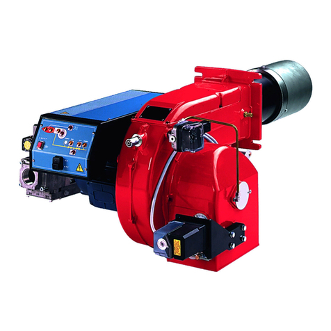
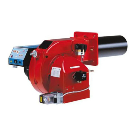
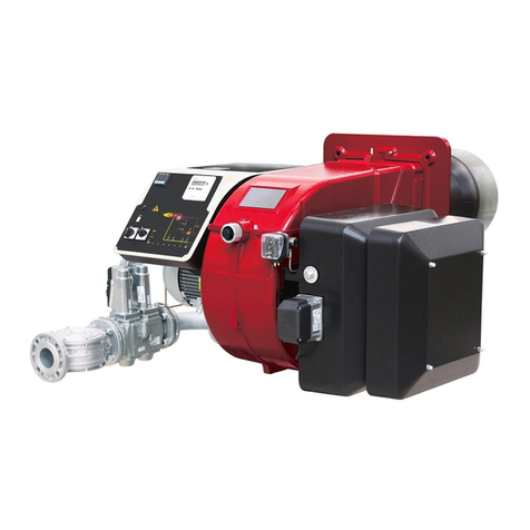
This particular burner series has been studied to use compressed air or alternatively steam, to atomize heavy oil. In this way we have
achieved higher efficiency compared to mechanical atomization. These burners are equipped with a low pressure nozzle which permits
to save fuel and, above all, to preserve the whole system. All burners are progressive type, complete with electrical panel, with self cle-
aning nozzle system and oil pump motor to be separately installed by the final user. A supplying system of compressed air and steam
at 8 bar must be provided on the site. All burners are ignited by means of a pilot flame burning LPG or Natural gas. The standard ver-
sion of the burner uses compressed air to atomize oil fuel. If compressed air is not available on site, it is possible to use steam to ato-
mise oil fuel by using a special kit. In any case compressed air is essential: to ignite the burner when steam is not available, to control
valves and for self cleaning nozzle.
Fig. 1
Note: the figure is indicative only.
1 Control panel
2Fanmotor
3 Electrical panel
4 Pressure governor
5 Oil pre-heater tank
6 Pilot gas train
7 Blast tube-combustion head
8 Burner flange
9 Burner cover
10 Oil train
11 Compressed air train
12 Air pressure switch
13 Air inlet
14 Adjusting cam
15 Actuator
PART I: INSTALLATION
10
11
5
6
432 1
89
12
7
13
15
14
C.I.B. UNIGAS - M039126CE
6
Burner model identification
Burners are identified by burner type and model. Burner model identification is described as follows.
Technical Specifications
Heavy oil net calorific value (Hi): 9650 kcal/kg or 40395 kJ/kg (average value).
*NOTE ON THE BURNER WORKING SERVICE: for safety reasons, one controlled shutdown must be performed after 24 hours
of continuous operation.
WARNING: the burners are supplied for 400V three phase supply; in case of three phase 230V supply, replace the thermal overload
relays. Maximum output is referred to a null backpressure in the furnace.
Type PBY1025 Model D-. PR. S. *. A.
(1) (2) (3) (4) (5) (6)
(1) BURNER TYPE PBY1025 - PBY1030 - PBY1040
(2) FUEL H - heavy oil, viscosity ≤4000cSt (530°E) @ 50°C
(3) OPERATION (Available versions) PR - Progressive MD - Fully modulating
(4) BLAST TUBE S - Standard L - Extended
(5) DESTINATION COUNTRY * - see data plate
(6) BURNER VERSION A - Standard
BURNER PBY1025 PBY1030 PBY1040
Output min - max kW 2550 - 8700 2550 - 10000 2550 - 13000
Fuel Heavy oil
Viscosity See “Burner model identification” table
Heavy oil rate min. - max. kg/h 227 - 775 227 - 891 227 - 1160
Gas pressure max. mbar 500
Gas pressure after gas governor mbar 100
Compressed air pressure min - max bar 4 - 10
Power supply 400V 3N a.c. 50Hz
Total power consumption kW 44.1 59.6 79.6
Fan motor kW 18.5 22 30
Pump motor kW 1.1 1.1 1.1
Pre-heater resistors kW 24 36 48
Protection IP40
Protection (if provided with light oil pilot) IP21
Operation Progressive - Fully modulating
Operating temperature °C (-10) / (+50)
Storage Temperature °C (-20) / (+60)
Working service* Intermittent
C.I.B. UNIGAS - M039126CE
7
Performance Curves
To get the input in kcal/h, multiply value in kW by 860.
Data are referred to standard conditions: atmospheric pressure at 1013mbar, ambient temperature at 15°C
NOTE: The performance curve is a diagram that represents the burner performance in the type approval phase or in the laboratory
tests, but does not represent the regulation range of the machine. On this diagram the maximum output point is usually reached by adj-
suting the combustion head to its “MAX” position (see paragraph “Adjusting the combustion head”); the minimum output point is rea-
ched setting the combustion head to its “MIN” position. During the first ignition, the combustion head is set in order to find a
compromise between the burner output and the generator specifications, that is why the minimum output may be different from the Per-
formance curve minimum.
The burner is designed to work positioned according to the picture below. Set the upper side of the burner flange in a horizontal posi-
tion, in order to find the correct inclination of the pre-heater tank. For different installations, please contact the Technical Department.
Key
1 Burner flange (upper side indicated)
2 Bracket
3 Pre-heater tank on the burner
PRESSURE IN
COMBUSTION CHAMBER (mbar)
PBY1025
kW
PBY1030
kW
PRESSURE IN
COMBUSTION CHAMBER (mbar)
PBY1040
0
10
20
30
2500 3500 4500 5500 6500 7500 8500
0
4
8
12
16
20
24
28
32
2000 3000 4000 5000 6000 7000 8000 9000 10000 11000
0
10
20
2000 3000 4000 5000 6000 7000 8000 9000 10000 11000 12000 13000
kW
SIDE UP
SIDE
DOWN
1
2
3
C.I.B. UNIGAS - M039126CE
8
Overall dimensions (mm)
*S = measure referred to burner fitted with standard blast tube
*L = measure referred to burner fitted with extended blast tube
PBY1030/1040: It is necessary to place a counterflange between the burner and the boiler.
A(*S) A(*L) AA AD AH AI AM B(*S) B(*L) BB C CC D E F G H K L M N O P PP QQ RR SS T W Y Z
PBY1025 1784 1980 377 25 304 404 335 376 572 641 1408 680 1312 680 632 472 522 660 815 M16 651 460 460 x x 265 80 49 1145 379 330
PBY1030 1761 2006 377 25 138 608 589 353 598 657 1408 680 1312 680 632 633 524 660 815 M16 x 460 460 800 900 265 80 49 1145 400 330
PBY1040 1769 1988 377 25 138 608 589 361 580 657 1408 680 1312 680 632 671 731 660 815 M16 x 460 800 800 900 265 80 49 1145 400 330
Boiler recommended drilling
template (PBY1025)
Burner flange
Reccomended counterflange
(PBY1030/1040)
Boiler recommended drilling
template (PBY1030/1040)
C.I.B. UNIGAS - M039126CE
9
PBY1025
Fig. 2 - (3I2D-02 v4) Hydraulic diagram
M
M
M
PI
PI
PI
PS
PS
PSL
TC
TC
TC
M
PI
PI
PI
ON BOARD ITEMS SUPPLIED LOOSE ITEMS
compressed air
to the tank
natural gas / LPG
combustion air
LPG gas - out of Cib Unigas scope of supply
BY BURNER CONSTRUCTOR
BY OTHERS
LEGEND
POS OIL TRAIN
1 Filter
2 Pump with electromotor
3 Flexible hose
4 Maual valve
5 Pressure gauge
6 Pressure governor
7 Maual valve
11 Electrical preheater tank
12 Temperature probe
13 Temperature probe
14 Temperature probe
16 Pneumatic valve
17 Metering valve with servomotor
18 Actuator
19 Maual valve
20 Pressure gauge
21 Flexible hose
COMPRESSED AIR TRAIN (ATOMIZATION)
40 Pressure governor with filter
41 Pressure gauge
42 Solenoid valve
43 Pressure switch
44 One-way valve
45 Metering valve
46 Manual valve
47 Pressure gauge
48 Flexible hose
COMPRESSED AIR TRAIN (PURGE)
50 Pressure governor with filter
51 Pressure gauge
52 Solenoid valve
53 One-way valve
PILOT GAS TRAIN
71 Pressure governor with filter
72 Pressure switch
73 Solenoid valve
74 Flexible hose
75 Pilot burner
76 Pressure governor for L.P.G. tank
77 Manual valve
78 Pressure gauge
79 L.P.G. tank
COMBUSTION AIR TRAIN
80 Air damper
81 Actuator
82 Remote draught fan with electromotor
83 Pressure switch - PA
86 Burner
The following items are out of CIB UNIGAS scope of supply: 77 - 78 - 79
oil inlet
C.I.B. UNIGAS - M039126CE
10
PBY1030 - PBY1040
Fig. 3 - (3I2D-03 v5) Hydraulic diagram
M
M
M
PI
PI
PI
PS
PS
PSL
M
PI
PI
PI
TC
TC
TC
TSHTS TSL
ON BOARD ITEMS SUPPLIED LOOSE ITEMS
compressed air
to the tank
natural gas / LPG
combustion air
LPG gas - out of Cib Unigas scope of supply
BY BURNER CONSTRUCTOR
BY OTHERS
LEGEND
POS OIL TRAIN
1 Filter
2 Pump with electromotor
3 Flexible hose
4 Maual valve
5 Pressure gauge
6 Pressure governor
7 Maual valve
8 Thermostat
9 Low thermostat
10 High thermostat
11 Electrical preheater tank
12 Temperature probe
13 Temperature probe
14 Temperature probe
16 Pneumatic valve
17 Metering valve with servomotor
18 Actuator
19 Maual valve
20 Pressure gauge
21 Flexible hose
COMPRESSED AIR TRAIN (ATOMIZATION)
40 Pressure governor with filter
41 Pressure gauge
42 Solenoid valve
43 Pressure switch
44 One-way valve
45 Metering valve
46 Manual valve
47 Pressure gauge
48 Flexible hose
COMPRESSED AIR TRAIN (PURGE)
50 Pressure governor with filter
51 Pressure gauge
52 Solenoid valve
53 One-way valve
PILOT GAS TRAIN
71 Pressure governor with filter
72 Pressure switch
73 Solenoid valve
74 Flexible hose
75 Pilot burner
76 Pressure governor for L.P.G. tank
77 Manual valve
78 Pressure gauge
79 L.P.G. tank
COMBUSTION AIR TRAIN
80 Air damper
81 Actuator
82 Remote draught fan with electromotor
83 Pressure switch - PA
86 Burner
The following items are out of CIB UNIGAS scope of supply: 77 - 78 - 79
oil inlet
C.I.B. UNIGAS - M039126CE
11
INSTALLING THE BURNER
Packing
Burners are despatched in wooden crates whose dimensions are:
z2280 mm x 1730 mm x 1360 mm(L x P x H)
Packing cases of this kind are affected by humidity and are not suitable for stacking. The fol-
lowing are placed in each packing case:
zburner;
zceramic fibre plait to be inserted between the burner and the boiler;
zoil flexible hoses;
zoil filter;
zoil pump with motor;
zenvelope containing this manual.
To get rid of the burner’s packing, follow the procedures laid down by current laws on disposal of materials.
Handling the burner
The burner is mounted on a stirrup provided for handling the burner by means of a fork lift truck: the forks must be inserted into the A
anb B ways. Remove the stirrup only once the burner is installed to the boiler.
Fitting the burner to the boiler
To perform the installation, proceed as follows:
1 drill the furnace plateas decribed in paragraph (“Overall dimensions”);
2 place the burner towards the furnace plate: lift and move the burner by means of its eyebolts placed on the top side (see”Lifting and
moving the burner”);
3 screw the stud bolts (5) in the plate holes, according to the burner’s drilling plate described on paragraph “Overall dimensions”;
4 place the ceramic fibre plait on the burner flange;
5 install the burner into the boiler;
6 fix the burner to the stud bolts, by means of the fixing nuts, according to the picture below.
7 After fitting the burner to the boiler, ensure that the gap between the blast tube and the refractory lining is sealed with appropriate
insulating material (ceramic fibre cord or refractory cement).
;
ATTENTION! The lhandling operations must be carried out by specialised and trained personnel. If these opera-
tions are not carried out correctly, the residual risk for the burner to overturn and fall down still persists.
To move the burner, use means suitable to support its weight (see paragraph “Technical specifications”).
The unpacked burner must be lifted and moved only by means of a fork lift truck.
H
PL
H
PL
AB
Keys
1 Burner
2 Fixing nut
3 Washer
4 Ceramic fibre plait
5 Stud bolt
7 Blast tube
4
C.I.B. UNIGAS - M039126CE
12
Electrical connections
To execute the electrical connections, proceed as follows:
1 remove the cover from the electrical board, unscrewing the fixing screws;
2 execute the electrical connections to the supply terminal board as shown in the following diagrams,
3 check the direction of the fan-pump motor (see next pargraph)
4 refit the panel cover
Respect the basic safety rules. Make sure of the connection to the earthing system. do not reverse the phase and
neutral connections. Fit a differential thermal magnet switch adequate for connection to the mains.
ATTENTION: before executing the electrical connections, pay attention to turn the plant’s switch to OFF and be
sure that the burner’s main switch is in 0 position (OFF) too. Read carefully the chapter “WARNINGS”, and the
“Electrical connections” section.
WARNING: The burner is provided with an electrical bridge between terminals 6 and 7; when connecting the
high/low flame thermostat, remove this bridge before connecting the thermostat.
IMPORTANT: Connecting electrical supply wires to the burner teminal block MA, be sure that the ground wire is
longer than phase and neutral ones.
auxiliary contacts are provided (terminals no. 507 and no. 508 of the MA terminal block) to connect an interven-
tion system (alarm/power supply cutoff) in case of fault of the oil resistor contactor (see Fig. 4-Fig. 5).
Fig. 4 - Progressive burners
Fig. 5 - Fully modulating burners
(#) Free contact for ”Faulty heater resistor contactor”
(**) Probes connection (see Fig. 6)
Probes connection
Fig. 6
Probes connection by means of the 7-pins plug (Fig. 7) - see Fig. 6 for con-
nections.
Fig. 7
MA
(#)
MA
(#)
C.I.B. UNIGAS - M039126CE
13
Fan motor and pump motor direction
Once the electrical connection of the burner is performed, remember to check the rotation of the motor. The motor should rotate accor-
ding to the arrow shown on the next picture. In the event of incorrect rotation reverse the three-phase supply and check again the rota-
tion of the motor.
NOTE: burners are supplied for three-phase 400 V supply, and in the case of three-phase 230 V supply it is necessary to modify the
electrical connections inside the terminal box of the electric motor and replace the thermal cutout relay.
Connecting the oil heating resistors
2.4 - 4.5 kW
Fig. 8
8 - 12 kW
Fig. 9
18 - 24 kW
Fig. 10
ELECTRIC MOTOR CONNECTION
Fig. 11
R1 R1
230V400V
R2 R2
R3 R3
L3 L3
L2 L2
L1 L1
R1
R1
230V400V
R2
R2
R3
R3
R4
R4
R5
R5
R6
R6
L3L3
L2
L2
L1
L1
R1
230V400 V
R1
R2
R2
R3
R3
R4
R4
R5
R5
R6
R6
L3
L3
L2
L2
L1
L1
230V400 V
W2 U2 V2
U1 V1 W1
W2 U2 V2
U1 V1 W1
L1 L2 L3
L1 L2 L3
C.I.B. UNIGAS - M039126CE
14
RECOMMENDATIONS TO DESIGN HEAVY OIL FEEDING PLANTS
This paragraph is intended to give some suggestions to make feeding plants for heavy oil burners. To get a regular burner operation, it
is very important to design the supplying system properly. Here some suggestions will be mentioned to give a brief description.
The term “heavy oil” is generic and summarises several chemical-physical properties, above all viscosity. The excessive viscosity
makes the oil impossible to be pumped, so it must be heated to let it flow in the pipeline; because of the low-boiling hydrocarbons and
dissolved gases, the oil must be also pressurised. The pressurisation is also necessary to feed the burner pump avoiding its cavitation
because of the high suction at the inlet. The supplying system scope is to pump and heat oil.
The oil viscosity is referred in various unit measures; the most common are: °E, cSt, Saybolt and Redwood scales. Table 3 shows the-
various unit convertions (e.g.: 132 cSt viscosity corresponds to 17.5°E viscosity).
The diagram in Fig. 12 shows how the heavy oil viscosity changes according to its temperature.
Example: an oil with 22°E viscosity at 50°C once heated to 100°C gets a 3 °E viscosity.
As far as the pumping capability, it depends on the type of the pump that pushes the oil even if on diagram in Fig. 12 a generic limit is
quoted at about 100 °E, so it is recommended to refer to the specifications of the pump provided.
Usually the oil minimum temperature at the oil pump inlet increases as viscosity does, in order to make the oil easy to pump. Referring
to the diagram on Fig. 13, it is possible to realise that to pump an oil with 50°E viscosity at 50°C, it must be heated at about 80°C.
Pipe heating system
Pipe heating system must be provided, that is a system to heat pipes and plant components to mantain the viscosity in the pumping lim-
its. Higher the oil viscosity and lower the ambient temperature, more necessary the pipe heating system.
Inlet minimum pressure of the pump (both for supplying system and burner)
A very low pressure leads to cavitation (signalled by its peculiar noise): the pump manifacturer declares the minimum value. Therefore,
check the pump technical sheets.
By increasing the oil temperature, also the minimum inlet pressure at the pump must increase, to avoid the gassification of the oil low-
boiling products and the cavitation. The cavitation compromises the burner operation, it causes the pump to break too. The diagram on
Fig. 14 roughly shows the inlet pump pressure according to the oil temperature.
Pump operating maximum pressure (both for the supplying system and burner)
Remember that pumps and all the system components through which the oil circulates, feature an upper limit. Always read the techni-
cal documentation for each component. Schemes on Fig. 15 are taken from UNI 9248 "liquid fuel feeding lines from tank to burner"
standard and show how a feeding line should be designed. For other countries, see related laws in force. The pipe dimensioning, the
execution and the winding dimensioning and other construcitve details must be provided by the installer.
Adjusting the supplying oil ring
According to the heavy oil viscosity used, in the table below indicative temperature and pressure values to be set are shown.
Note: the temperature and pressure range allowed by the supplying ring components must be checked in the specifications table of the
components themselves.
Tab. 1 - Supply pipeline hydraulic scheme 3ID0024, pump n.4
HEAVY OIL VISCOSITY AT 50 °C PIPELINE
PRESSURE PIPELINE
TEMPERATURE
cSt (°E) bar °C
< 50 (7) 1- 2 20
> 50 (7) < 110 (15) 1- 2 50
> 110 (15) < 400 (50) 1- 2 65
> 400 (50) < 4000 (530) 1- 2 100
ATTENTION: Atomizing air pressure is tipically set at 1 bar lower than oil pressure.
C.I.B. UNIGAS - M039126CE
15
Viscosity units conversion table
Tab. 2
Cinematics
viscosity
Centistokes (cSt)
Engler Degrees
(°E)
Saybolt
Seconds
Universal
(SSU)
Saybolt
Seconds
Furol (SSF)
Redwood
Seconds no.1
(Standard)
Redwood Seconds
no..2 (Admiralty)
1 1 31 -- 29 --
2.56 1.16 35 -- 32.1 --
4.3 1.31 40 -- 36.2 5.1
7.4 1.58 50 -- 44.3 5.83
10.3 1.88 60 -- 52.3 6.77
13.1 2.17 70 12.95 60.9 7.6
15.7 2.45 80 13.7 69.2 8.44
18.2 2.73 90 14.44 77.6 9.3
20.6 3.02 100 15.24 85.6 10.12
32.1 4.48 150 19.3 128 14.48
43.2 5.92 200 23.5 170 18.9
54 7.35 250 28 212 23.45
65 8.79 300 32.5 254 28
87.6 11.7 400 41.9 338 37.1
110 14.6 500 51.6 423 46.2
132 17.5 600 61.4 508 55.4
154 20.45 700 71.1 592 64.6
176 23.35 800 81 677 73.8
198 26.3 900 91 762 83
220 29.2 1000 100.7 896 92.1
330 43.8 1500 150 1270 138.2
440 58.4 2000 200 1690 184.2
550 73 2500 250 2120 230
660 87.6 3000 300 2540 276
880 117 4000 400 3380 368
1100 146 5000 500 4230 461
1320 175 6000 600 5080 553
1540 204.5 7000 700 5920 645
1760 233.5 8000 800 6770 737
1980 263 9000 900 7620 829
2200 292 10000 1000 8460 921
3300 438 15000 1500 13700 --
4400 584 20000 2000 18400 --
C.I.B. UNIGAS - M039126CE
16
Fig. 12
VISCOSITY vs TEMPERATURE DIAGRAM FOR COMBUSTIBLE OILS
PUMPING LIMIT
1
10
100
1000
-10 0 10 20 30 40 50 60 70 80 90 100 110 120 130 140 150 160
TEMPERATURE (°C)
VISCOSITY (°E)
LIGHT OIL 1,3°E AT 20°C
HEAVY OIL 2,4°E AT 50°C
HEAVY OIL 4°E AT 50°C
HEAVY OIL 7,5°E AT 50°C
HEAVY OIL 10°E AT 50°C
HEAVY OIL 13°E AT 50°C
HEAVY OIL 22°E AT 50°C
HEAVY OIL 50°C
HEAVY OIL 47°E AT 50°C
HEAVY OIL 70°E AT 50°C
HEAVY OIL 200°E AT 50°C
C.I.B. UNIGAS - M039126CE
17
Indicative diagram showing the oil temperature at burner pump inlet vs. oil viscosity
Example: if the oil has a 50°E @ 50°C viscosity, the oil temperature at the pump inlet should be 80°C (see diagram).
Indicative diagram showing the oil pressure according to its temperature
OIL TEMPERATURE FOR PUMP FEEDING
1
10
100
0 102030405060708090
TEMPERATURE (°C)
VISCOSITY (°E a 50°C)
Fig. 13
PUMP FEEDING PRESSURE
Max. for E ..1069
pimps
Max. for T and
TA pumps
0
1
2
3
4
5
6
40 60 80 100 120 140 160
TEMPERATURE (°C)
PRESSURE (bar)
Fig. 14
C.I.B. UNIGAS - M039126CE
18
Fig. 15 - Hydraulic diagram 3ID0024
M
M
PI
PI
PI
TI
TS
TSLTSH
PSLPSH
PSLPSH
pressure
governor unit
oil pumping unit
heating medium inlet
heating medium outlet
main tank inlet
daily tank unit
BURNER 1
SEE THE BURNER
P&ID
BURNER 2
SEE THE BURNER
P&ID
heating medium inlet
heating medium outlet
3ID0024 KEYS
POS OIL TRAIN DAILY TANK
1 Main tank 10 Daily tank
OIL PUMPING UNIT 11 Heating device
2 Manual valve 12 Electrical resistor
3 Filter 13 Pressure gauge
4 Pump coupled to electrical motor 14 High pressure switch - PO MAX
5 Safety valve 15 Low pressure switch - PO MIN
6 One-way valve 16 Low thermostat - TCN
7 Manual valve 17 Thermometer
8 Pressure gauge 18 High thermostat - TRS
9 High pressure switch - PO MAX 19 Thermostat - TR
20 Manual valve
21 Manual valve
PRESSURE GOVERNOR UNIT
22 Pressure gauge
23 Manual valve
24 Pressure governor
25 Needle valve
PIPE HEATING SYSTEM: SEE MANUAL TEXT
C.I.B. UNIGAS - M039126CE
19
Pilot gas train
The connection to the pilot gas train must be done according to the following scheme, valid for LPG. In case of natural gas, connect the
pressure goveror (pos. 3) to the natural gas line (maximum input pressure = 1 bar).
Fig. 16
The pilot gas train is already installed into the burner, the connection from the filter with stabiliser to the gas supply network must be
carried out.
Once the gas train in installed, execute the electrical connections for all its items (gas valves group, pressure switch).
ATTENTION: once the gas train is mounted according to the diagram on Fig. 16, the gas proving test mus be per-
formed, according to the procedure set by the laws in force.
1
2
45
3
16
7
MANUFACTURER INSTALLER
L.P.G.
Key
(1) Gas valves
(2) Minimum gas pressure switch
(3) Gas pressure governor with filter
(4) Bellow joint (*)
(5) Manual cutoff valve (*)
(6) Pressure governor (*)
(7) Tank (*)
(*) = Not supplied
connection to the gas supply network - 1/2”
C.I.B. UNIGAS - M039126CE
20
Light oil pilot
The burner can be provided with light oil pilot, instead of gas pilot.
Heavy oil pumps
The pump provided with the burner must be installed according to the hydraulic diagram.
Cucchi FMG40 pumps
Capacity: 2500l/h
Power consumption: 1.1 kW
Speed: 1400 rpm
Max outlet pressure: 10bar
Max inlet pressure: 2bar
Min inlet pressure: -0.4bar
For further details see the manifacturer documentation.
Key
EVG Light oil solenoid valve
M Manometer
PPump
Fig. 17
Suntec TV Pressure governor
Pressure adjustment
Remove cap-nut 1 and the gasket 2, unscrew the lock nut 4. To increase pressure,
twist adjusting screw 3 clockwise.
To decrease the pressure, twist screw counterclockwise. Tight the lock nut 4, refit the
gasket 2 and the cap nut 1.
Key
1Capnut
2 Gasket
3 Adjusting screw
4 Lock nut
5 Gasket Fig. 18
light oil pilot nozzle light oil pilot pump
EVG
MP

This manual suits for next models

2

Other CIB UNIGAS Burner manuals

CIB UNIGAS E165A User manual

CIB UNIGAS

CIB UNIGAS E165A User manual

CIB UNIGAS 1030 User guide

CIB UNIGAS

CIB UNIGAS 1030 User guide

CIB UNIGAS N1060A Operating manual

CIB UNIGAS

CIB UNIGAS N1060A Operating manual

CIB UNIGAS G258A User manual

CIB UNIGAS

CIB UNIGAS G258A User manual

CIB UNIGAS HTP1030 Operating manual

CIB UNIGAS

CIB UNIGAS HTP1030 Operating manual

CIB UNIGAS TG1030 Operating manual

CIB UNIGAS

CIB UNIGAS TG1030 Operating manual

CIB UNIGAS KP72 Operating manual

CIB UNIGAS

CIB UNIGAS KP72 Operating manual

CIB UNIGAS PG60 Operating manual

CIB UNIGAS

CIB UNIGAS PG60 Operating manual

CIB UNIGAS P20 User manual

CIB UNIGAS

CIB UNIGAS P20 User manual

CIB UNIGAS HR91A Operating manual

CIB UNIGAS

CIB UNIGAS HR91A Operating manual

CIB UNIGAS RG91 Operating manual

CIB UNIGAS

CIB UNIGAS RG91 Operating manual

CIB UNIGAS PBY1025 Quick start guide

CIB UNIGAS

CIB UNIGAS PBY1025 Quick start guide

CIB UNIGAS RG1025 User manual

CIB UNIGAS

CIB UNIGAS RG1025 User manual

CIB UNIGAS R91A Quick start guide

CIB UNIGAS

CIB UNIGAS R91A Quick start guide

CIB UNIGAS TP90A Operating manual

CIB UNIGAS

CIB UNIGAS TP90A Operating manual

CIB UNIGAS HR92A Operating manual

CIB UNIGAS

CIB UNIGAS HR92A Operating manual

CIB UNIGAS R91A M Series Operating manual

CIB UNIGAS

CIB UNIGAS R91A M Series Operating manual

CIB UNIGAS Low NOx Series Operating manual

CIB UNIGAS

CIB UNIGAS Low NOx Series Operating manual

CIB UNIGAS PG30 Operating manual

CIB UNIGAS

CIB UNIGAS PG30 Operating manual

CIB UNIGAS Idea Series Operating manual

CIB UNIGAS

CIB UNIGAS Idea Series Operating manual

CIB UNIGAS KP91 User manual

CIB UNIGAS

CIB UNIGAS KP91 User manual

CIB UNIGAS KP60 Operating manual

CIB UNIGAS

CIB UNIGAS KP60 Operating manual

CIB UNIGAS Idea Series Operating manual

CIB UNIGAS

CIB UNIGAS Idea Series Operating manual

CIB UNIGAS R63 Operating manual

CIB UNIGAS

CIB UNIGAS R63 Operating manual

Popular Burner manuals by other brands

Cuenod GRANT 4 R LN instructions

Cuenod

Cuenod GRANT 4 R LN instructions

Jack Grills JGSDBL owner's manual

Jack Grills

Jack Grills JGSDBL owner's manual

ARCHPOT APF Installation and operation guide

ARCHPOT

ARCHPOT APF Installation and operation guide

Beckett CF1400 manual

Beckett

Beckett CF1400 manual

Zero IGNITION instruction manual

Zero

Zero IGNITION instruction manual

Town & Country Fireplaces TC42 installation instructions

Town & Country Fireplaces

Town & Country Fireplaces TC42 installation instructions

Nova Vizantija Bionova Round Burner L Installation and operation guide

Nova Vizantija

Nova Vizantija Bionova Round Burner L Installation and operation guide

Vauni OF Wide manual

Vauni

Vauni OF Wide manual

Riello RS 650/E BLU Installation, use and maintenance instructions

Riello

Riello RS 650/E BLU Installation, use and maintenance instructions

baltur BT 40G instructions

baltur

baltur BT 40G instructions

OERTLI AMERICAN OE-22 INSTALLATION SERVICE AND OPERATING MANUAL

OERTLI AMERICAN

OERTLI AMERICAN OE-22 INSTALLATION SERVICE AND OPERATING MANUAL

Eclipse Combustion ImmersoJet Series Design guide

Eclipse Combustion

Eclipse Combustion ImmersoJet Series Design guide

Megatherm Nani 35 Installation & user manual

Megatherm

Megatherm Nani 35 Installation & user manual

Beckett AF Series manual

Beckett

Beckett AF Series manual

Campingaz XCELERATE 600 SV Instructions for use

Campingaz

Campingaz XCELERATE 600 SV Instructions for use

Ecoflam AZUR 40 instructions

Ecoflam

Ecoflam AZUR 40 instructions

Varmebaronen Viking Bio 35 Installation and Maintenance

Varmebaronen

Varmebaronen Viking Bio 35 Installation and Maintenance

Jackson Grills JGSB-LP owner's manual

Jackson Grills

Jackson Grills JGSB-LP owner's manual

manuals.online logo
manuals.online logoBrands
  • About & Mission
  • Contact us
  • Privacy Policy
  • Terms and Conditions

Copyright 2025 Manuals.Online. All Rights Reserved.