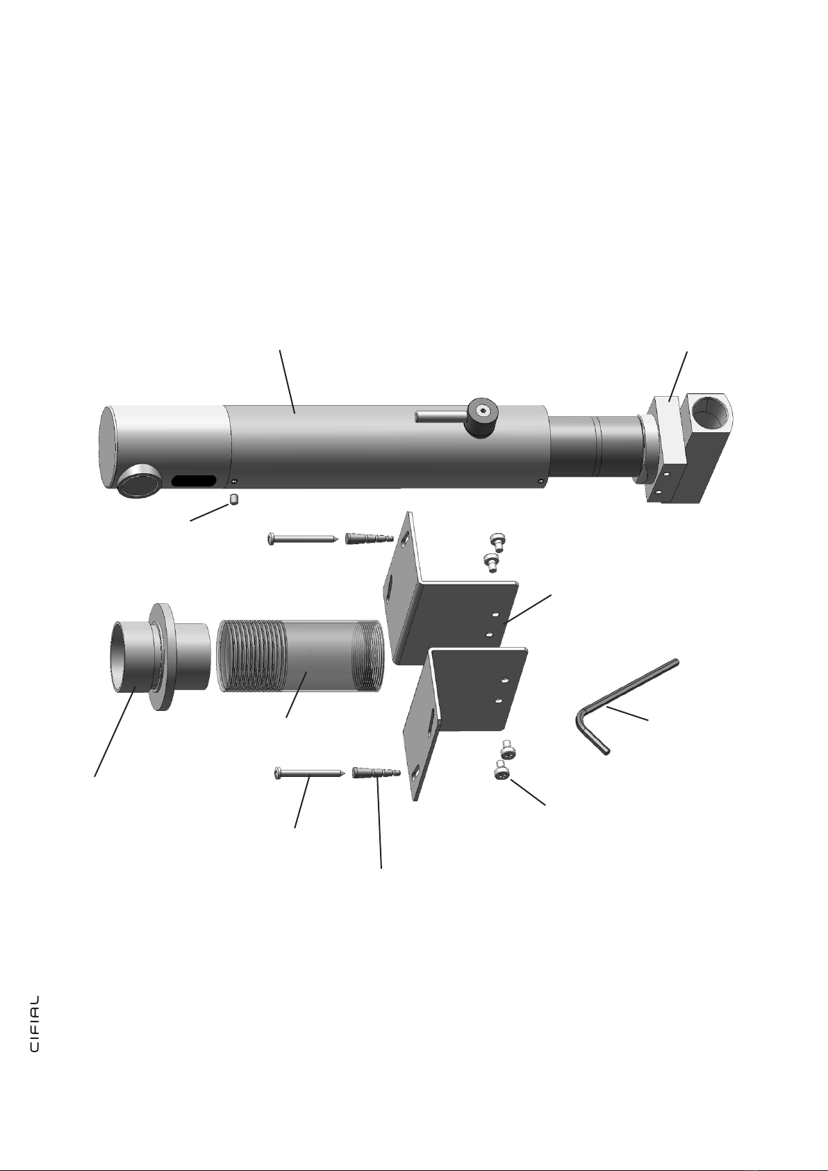
CIFIAL 3215001 User manual

TORNEIRA ELETRÓNICA DE PAREDE 3215001
WALL MOUNTED ELECTRONIC FAUCET 3215001
MANUAL DE MONTAGEM E INSTRUÇÕES
ASSEMBLEY AND INSTRUCTIONS MANUAL

INDICE
INDEX
03
04
05
06
07
08
09
10
11-12
13
DADOS TÉCNICOS
TECHNICAL DATA
CONTEÚDO DO PACK
PACK CONTENTS
INFORMAÇÃO DE PRÉ-INSTALAÇÃO
PRE-INSTALLATION INFO
INSTALAÇÃO
INSTALLATION
AJUSTE CONFIGURAÇÕES
RANGE ADJUSTMENT
SUBSTITUIÇÃO DE BATERIA
BATTERY REPLACEMENT
MANUTENÇÃO
MAINTENANCE
LISTA DE PEÇAS
SPARE PARTS LIST
RESOLUÇÃO DE PROBLEMAS
TROUBLE SHOOTING
GARANTIA
WARRANTY

3
Power supply :
Min operating water pressure:
Max operating water pressure:
Sensor range:
Minimum sensor range:
Maximum sensor range:
Security time:
Water max tempeture:
1x 9V Lithium battery
0.5 bar (7 PSI)
8.0 bar (116 PSI)
With water pressure of more than 8 Bars, use a pressure
reducing valve
Self adjusting sensor
80 mm
240 mm
90 seconds
70˚C
TORNEIRA ELETRÓNICA DE PAREDE 3215001
WALL MOUNTED ELETRONIC TAP 3215001
Fonte de alimentação:
Pressão min de água:
Pressão max de água:
Alcance do sensor:
Alcance min do sensor:
Alcance max do sensor:
Tempo de segurança:
Temperatura max da água:
1x Pilha Lítio de 9V
0.5 bar (7 PSI)
8.0 bar (116 PSI)
Com pressão de água superior a 8.0 bar, utilizar uma válvula
de redução
Sensor com ajuste automático
80 mm
240 mm
90 seconds
70˚C

4
CONTEÚDO DO PACK
PACK CONTENTS
base
base
Roseta de parede
Wall rosette
Bica e acessórios (incl. unidade eletrónica)
Spout and attachments (incl. electronic unit)
Perno M4x4
M4x4 set screw
Capa protetora temporária
Temporary protection cover
2x Parafuso 6x1 1/2”
2x Srew 6x1 1/2”
2x Buchas 5x25
2x Screw anchors 5x25
4x Parafusos M4x6
4x M4x6 Screw
2x Suportes Angulares
2x Angle suport
Chave sextavada 2mm
Allen key 2mm

5
Check contents
Separate all parts from the packaging and check each part
with the pack contents section.
Make sure all parts are accounted for before discarding any
packaging material.
If any parts are missing, do not attempt to install your elec-
tronic faucet until you obtain the missing parts.
INFORMAÇÃO DE PRÉ-INSTALAÇÃO
PRE-INSTALLATION INFO
Verifique o conteúdo
Separe todas as peças da embalagem e verifique cada peça
com a lista de componentes da embalagem.
Certifique-se de que todos os componentes necessários
estão presentes antes de desembalar.
Se faltar algum componente, não instale a torneira até ter
todos os componentes em falta.
Para evitar problemas de sinal refletido
To avoid reflection problems
1) Mantenha uma distância superior a 300 mm entre o
lavatório e a torneira.
2) Este modelo de torneira, é composto por um sensor de
infravermelhos que aponta para baixo, não se destina a
ser utilizado em conjunto com um lavatório de um material
refletor, tal como o aço inox polido.
3) Se o escoador estiver diretamente por baixo do sensor
da torneira, use um escoador com um acabamento não
refletivo (não use o acabamento cromado).
Não instale um escoador brilhante na direção do sensor.
1) To avoid reflection problems keep a distance of
more than 300 mm. between the sink and the spout.
2) This faucet model, with an infrared sensor pointing
down, is not intended to be used together with a sink of a
reflective material such as high polished stainless steel.
3) If a sink strainer is straight below the faucet sensor, use
a strainer with a non reflective finish (do not use a chrome
plated one).
Do not place a shiny pop up in front of the sensor.
Fundo do lavatório
Bottom of the wasbasin
Min. 300 mm
Preparação para instalação
Verificar se todas ligações estão devidamente limpas. Não de-
vem existir sujidades, fita de teflon ou partículas metálicas que
possam entrar na torneira. Risco de obstruir a saída da água.
Importante
Todas as canalizações devem estar de acordo com as normas
e regulações.
Preparation for installation
Flush water supply lines thoroughly before installing the fau-
cet. Do not allow dirt, Teflon tape or metal particles to enter
the faucet. Shut off water supply.
Important
All plumbing is to be installed in accordance with applicable
codes and regulations.

6
1. Shut off the water supply
2. Prepare the support bar at the faucet base by assembling the
angle supports with the 4 provided screws.
3. Cut an adequate opening in the wall at the place where you
want to install the spout of the faucet.
4. Drill two orifices at the wall for the anchors.
cut in the wall, and set it using the four M4 x 6 screws.
5. Mount the faucet base to the opening cut in the wall, and set it
using the two 3,5 x 11/2” provide screws.
6. During the base fixation process, pay attention to the alignment.
The faucet base should be installed so that the outside surface
of the finished wall falls between the minimum and maximum lines
marked at protective plastic cover.
7. The protective plastic cover should be installed at the faucet
base until the tiles work is finished.
8. At this point, cut the temporary protective cover at the proper
mark at the wall level.
9. Connect the hot and cold water supply pipes to the faucet base
10. Screw the wall rosette to the faucet base.
11. Install the faucet to the rosette; close the set screw using the 2
mm Allen key. Make sure that the faucet is properly aligned so that
sensor is facing down.
12. Remove the protective sticker that covers the sensor
13. Open the water supply.
14. Check for leaks
NOTE: This faucet includes a special aerator that allows you to
adjust the water stream direction on site in order to prevent water
splashing if needed. To change the angle of the water stream, sim-
ply move the adjustable tilting plate by pressing it smoothly.
If the sensor range is not satisfactory, please refer to the section
entitled “Settings adjustment”.
INSTALAÇÃO
INSTALLATION
1. Feche o fornecimento de água.
2. Preparar a base da torneira instalando os suportes de 90º para
fixação da torneira com os quatro parafusos M4x6 fornecidos.
3. Faça uma abertura adequada na parede onde pretende instalar
a torneira.
4. Faça dois furos na parede para as buchas fornecidas.
5. Instale a base da torneira na abertura da parede e fixe-a usando
os dois parafusos 3.5x11/2” fornecidos.
6. Durante o processo de instalação, preste atenção ao alinhamen-
to. A base da torneira deve ser instalada de modo que a superfície
exterior da parede acabada se situe entre o mínimo e o máximo
das linhas marcadas na capa de proteção temporária.
7. A capa de proteção temporária deve permanecer na base da
torneira até que o trabalho de assentamento dos azulejos esteja
finalizado.
8. Neste momento, corte a capa de proteção temporária na marca
adequada ao nível da parede.
9. Ligue os tubos de abastecimento de água quente e fria a base
da torneira.
10. Rosque a roseta de parede a base da torneira.
11. Instale a torneira na roseta, fixe-a com o perno M4x4 fornecido
com a ajuda da chave sextavada 2mm também fornecida.
12. Remova a película protetora que protege o sensor.
13. Abra o fornecimento de água.
14. Verifique se há fugas.
NOTA: Esta torneira esta equipada com um emulsor especial que
lhe permite ajustar a direção do fluxo de água no local, a fim de
evitar salpicos de água, se necessário. Para alterar o ângulo do
fluxo de água, movimente simplesmente o emulsor de inclinação
regulável, pressionando-o suavemente.

7
AJUSTE CONFIGURAÇÕES
RANGE ADJUSTMENT
Adjusting the sensor range:
1. Shut off the water supply
2. Disconnect the power supply, battery or transformer from the
sensor.
3. Make a short circuit between the (+) and the (-) of the sensor.
You can use a screw driver or another conductor material to make
this short circuit. Alternatively, after disconnecting the power sup-
ply, activate the sensor three or four times.
Do not make a short circuit on the power supply or on the
sensor when the power supply is connected to the sensor.
4. Reconnect the power supply to the sensor.
5. To enter into the adjusting mode, you have to put your hand in
front of the sensor at a distance of 2” (5cm) to 4” (10cm) from
the sensor within 5 seconds from the reconnection of the power
supply.
Note: if you will not put your hand in front of the sensor after con-
necting the power supply, the sensor will not enter into adjusting
mode and the previous adjustment will return.
6. When the sensor enters into adjusting mode and your hand is
in front of the sensor, a slow flashing of the red light in front of the
sensor will occur.
7. Keep your hand in front of the sensor until the slow flashing
changes to quick flashing. At this point, move your hand to the
required distance from the sensor and wait until the red light will
stop flashing.
8. When the red light has turned off, the sensor is adjusted to the
required distance.
9. Check the distance you have set and if it is not satisfactory,
repeat steps 1-7.
10. Turn on the water supply.
Regulação do alcance:
1. Feche o fornecimento de água.
2. Desligue a fonte de alimentação, (porta pilhas ou transformador)
do sensor.
3. Faça um curto-circuito entre o (+) e o (-) do sensor. Pode
utilizar uma chave de parafusos ou outro objeto condutor qualquer
para provocar o curto-circuito. Alternativamente, depois de desli-
gar a fonte de alimentação, ligue o sensor três ou quatro vezes.
Não faça o curto-circuito na fonte de alimentação ou no sen-
sor quando a fonte de alimentação está conectada ao sensor.
4. Volte a ligar a fonte de alimentação ao sensor.
5. Para executar o ajuste do sensor, você tem que colocar a mão
na frente do sensor a uma distância entre 2” (50 mm) e 4” (100
mm) a partir do sensor dentro de 5 segundos após a ligação do
fornecimento de energia.
Nota: Se não colocar a mão em frente ao sensor depois de ligar a
fonte de alimentação, o sensor não vai entrar no modo de ajuste e
voltará ao ajuste anterior.
6. Quando o sensor entra no modo de ajuste e a sua mão está a
frente do sensor, irá surgir uma luz vermelha intermitente lenta na
frente do sensor.
7. Mantenha a sua mão na frente do sensor até que o intermitente
lento passe a intermitente rápido. Neste momento, mova a sua
mão para a distância pretendida do sensor e espere até que a luz
vermelha pare de piscar.
8. Quando a luz do sensor desligar, o sensor está regulado para a
distância pretendia.
9. Teste a distância que registou e se não estiver satisfeito, repita
os passos 1-7.
10. Ligue o fornecimento de água.

8
Low battery indicator
When the battery weakens, the red indicator light will blink
at a constant rate when the user’s hands are within the sen-
sor range.
The battery must be replaced within two weeks, as fol-
lows:
1. Close the water supply
2. To reach access to the battery, unscrew the set screw
located at the underside part of the faucet body using the
Allen key provided (2mm).
3. Disassemble the sensor cap.
4. Verify that the O-ring is in good condition. If needed, ap-
ply grease or replace it.
5. Take out the battery cover protection and remove the old
battery, disconnect from the battery connector.
6. Place the battery cover protection at the new battery
and connect to the battery connector. A Lithium battery is
recommended.
7. This model includes a self adjusting sensor. Reassemble
the parts without setting the screw, and move away from
the sensor range. No objects should be placed between the
sensor and the washbasin. As an indication that the self ad-
justment has taken place, the solenoid valve will be opened
and closed for 1 second the product is ready for use.
8. Open the water
9. Fix the body with the set screw.
SUBSTITUIÇÃO DE BATERIA
BATTERY REPLACEMENT
Indicador de pilha baixa
Quando a pilha 9V ficar sem carga, a luz indicadora ver-
melha piscará constantemente sempre que as mãos do
utilizador se aproximem do alcance do sensor.
A pilha 9V deve ser substituída dentro de duas sema-
nas, do seguinte modo:
1. Corte o fornecimento de água.
2. Para ter acesso a pilha 9V, desaperte o perno de fixação
localizado na parte inferior do corpo da torneira usando a
chave sextavada 2 mm fornecida.
3. Desmonte a tampa do sensor.
4. Verifique se o O-ring se encontra em perfeitas condições.
Se necessitar, lubrifique ou substitua.
5. Remova a pilha 9V antiga, retire a capa de proteção da
pilha 9V e desligue os conetores da pilha 9V.
6. Na nova pilha 9V, ligue os conetores e coloque a capa de
proteção da pilha 9V. Recomenda-se a utilização de uma
pilha 9V de Lítio.
7. A torneira esta equipada com um sensor de ajuste au-
tomático. Instale de novo o corpo da torneira sem apertar
o perno e afaste-se do alcance do sensor. Nenhum objeto
deve interferir entre o sensor e o lavatório. Como indicação
de que o ajuste automático ocorreu, a válvula solenóide
abrirá e fechará durante 1 segundo, indicando que o
produto está pronto a utilizar.
8. Abra de novo o fornecimento de água.
9. Fixe o corpo com o perno.
IMPORTANTE: Se o alcance do sensor não é satisfatória, por favor, consulte a seção intitulada
“ajuste Configurações”.
IMPORTANT: If the sensor range is not satisfactory, please refer to the section entitled “Settings adjustment”.
Aguarde 15 segundos de forma ao sistema definir a amplitude ideal do
sensor.
Wait about 15 seconds in order to allow the system to set the ideal
sensor range.

9
Instruções de limpeza dos filtros
a. Desligar o abastecimento de água e a válvula.
b. Desaperte o parafuso de fixação no corpo da torneira
com a chave sextavada de 2 mm fornecida.
c. Puxe o corpo da torneira de maneira a o separar da
roseta.
d. Neste ponto, você terá acesso aos dois tubos de ali-
mentação e ao parafuso sextavado que estão localizados
no interior da torneira. Desaparafuse o parafuso usando a
chave sextavada de 4 mm fornecida.
e. Retire os tubos de alimentação e desmonte os filtros.
f. Limpe os filtros debaixo de água a correr. Se necessário,
substituir por novos.
g. Reinstalar os filtros. Reinstalar os tubos de alimentação
e fechar a central com o parafuso utilizando a chave sexta-
vada.
h. Instale novamente o corpo da torneira na base fixando-o
à roseta com o perno.
i. Ligue o abastecimento de água.
j. Verifique possíveis fugas.
MANUTENÇÃO
MAINTENANCE
Filters cleaning instructions
a. Shut-off the water supply and the valve.
b. Release the set screw at the faucet body using the 2 mm
Allen Key.
c. Pull out the Faucet body and separate it from the rosette.
d. At this point you will have access to the two nipples and
the Allen screw that are located at the internal side of the
faucet. Unscrew this screw using the provided 4mm Allen
key.
e. Pull out the nipples and dismount the filters.
f. Wash the filters under running water. If needed, replace the
filters with new ones.
g. Restore the filters. Restore the nipples and close the cen-
tral screw using the Allen key.
h. Reassemble the faucet body to the base with the rosette
setting the screw.
i. Re-establish the incoming water supply.
j. Make sure that there is no water leakage.
Cuidado e limpeza de cromados e acabamentos especiais.
NÃO use esfregão de aço ou artigos de limpeza que con-
tenham álcool, ácidos, abrasivos ou semelhantes. O uso de
quaisquer produtos de limpeza, de manutenção ou sub-
stancias proibidas podem danificar a superfície da torneira.
Para a limpeza da superfície da torneira use APENAS sabão
e água, em seguida seque com um pano limpo ou toalha.
Quando fizer a limpeza dos azulejos das paredes, as tornei-
ras devem ser protegidas de qualquer projeção de produtos
abrasivos.
Care and cleaning of chrome and special finishes.
DO NOT use steel wool or cleansing agents containing
alcohol, acid, abrasives, or the like. Use of any prohibited
cleaning or maintenance products or substances could dam-
age the surface of the faucet. For surface cleaning of faucet
us ONLY soap and water, then wipe dry with clean cloth or
towel. When cleaning bathroom tile, the faucets should be
protected from any splattering of harsh cleansers.

10
LISTA DE PEÇAS
SPARTE PARTS LIST
Kit Sensor
Sensor Kit
Válvula solenóide
Solenoid valve
Tampa das pilhas
Battery cover
Filtro
Filter
07220082
07500065
06500001
08530014

11
RESOLUÇÃO DE PROBLEMAS
TROUBLESHOOTING
PROBLEMA INDICADOR CAUSA SOLUÇÃO
Não sai água na
torneira:
1- O sensor pisca continu-
amente quando o utilizador
coloca as mãos no alcance
do sensor.
Pilhas sem carga. Substituir a pilha 9V.
2- A luz vermelha no sen-
sor não pisca quando o
utilizador coloca as mãos
no alcance do sensor.
1- Alcance muito curto.
2- Alcance muito longo.
3- Pilhas completamente esgotadas.
4- A unidade está em “Modo Segurança” *.
5- O sensor está com reflexos do lav-
atório ou outro objeto .
Aumentar o alcance.
Diminuir o alcance.
A pilha 9V deve ser substituída.
Eliminar a causa do reflexo.
3- A luz vermelha no
sensor pisca quando o
utilizador coloca as mãos
no alcance do sensor.
1- Os conetores entre a unidade eletróni-
ca e a solenóide estão desligados.
2- Detritos ou calcário na solenóide.
3- O orifício central do diafragma está
obstruído ou o diafragma está danificado.
4- A pressão da água está a cima dos
8 bar.
Ligar os conetores entre a unidade eletrónica e a
solenóide.
Desaparafuse a solenóide, extraia o pistão e a mola
da solenóide e limpe-os. Use um removedor de cal-
cário se necessário. Quando substituir o pistão, tenha
a certeza que a mola fica na posição vertical.
Limpe o orifício ou substitua o diafragma.
Reduza a pressão da água.
O fluxo de água que sai
da torneira não para:
1- O sensor pisca uma vez
quando o utilizador coloca as
mãos no alcance do sensor.
2- A luz vermelha no sen-
sor não pisca quando o
utilizador coloca as mãos
no alcance do sensor.
Detritos ou calcário no diafragma.
1- O sensor está sujo ou coberto.
2- O sensor está com reflexo do lavatório
ou outro objeto.
Limpe o orifício ou substitua o diafragma.
Limpe ou elimine possíveis interferências.
Eliminar a causa do reflexo.
Fluxo de água reduzido: O filtro ou o emulsor estão obstruídos. Retire, limpe e volte a instalar.
* Modo Segurança – Se o sensor está fechado por mais de 90 segundos, a torneira ficará automaticamente sem fluxo de
água. Para voltar ao funcionamento normal, remova qualquer bloqueio para restabelecer o funcionamento.

12
RESOLUÇÃO DE PROBLEMAS
TROUBLESHOOTING
PROBLEM INDICATOR CAUSE SOLUTIONS
No water coming out
of the Faucet:
1.Sensor flashes continu-
ously when user’s hands
are within the sensor’s
range.
Low battery. Replace battery.
2. Red light in the sensor
does not flash (once) when
user’s hands are within the
sensor range.
1. Range is too short.
2. Range is too long.
3. Battery is completely used up
4. Unit is in “Security Mode” *
5. Sensor is picking up reflections from
the washbasin or another
object..
Increase the range.
Decrease the range.
The battery must be replaced.
Eliminate cause of reflection.
3. Red light in the sensor
flashes once when user’s
hands are within the sen-
sor range.
1. Connectors between the electronic
unit and solenoid are disconnected.
2. Debris or scale in solenoid.
3. The central orifice in the diaphragm is
plugged or the diaphragm is torn.
4. The water supply pressure is higher
than 8 bar.
Connect the electronic unit connectors to the solenoid.
Unscrew solenoid, pull out the plunger and the spring
from the solenoid and clean them. Use scale remover
material if needed. When replacing the plunger,
please make sure that the spring is in vertical position.
Clean the orifice or replace diaphragm.
Reduce the supply water pressure.
Water flow from spout
does not stop:
1. Sensor flashes once
when user’s hands are
within the sensor’s range.
2. Red light in the sensor
does not flash (once) when
user’s hands are within the
sensor’s range.
Debris or scale in diaphragm.
1. Sensor is dirty or covered.
2. Sensor is picking up reflections from
the washbasin or another object.
Clean the orifice or replace diaphragm.
Clean or eliminate case of interference.
Decrease the range or eliminate cause of reflection.
Water flow diminished: Filter or aerator is clogged. Remove, clean, re-install.
* “Security Mode”: If the sensor is covered for more than 90 sec. the faucet will automatically shut off water flow. To return to
normal operation remove any blockage to re-establish operation.

13
1. PRAZOS DE GARANTIA
- Torneiras: 10 anos (2 anos de garantia legal mais 8 de garantia adicional);
- Colunas de duche: 2 anos de garantia legal;
- Chuveiros, fl exíveis e barras de chuveiro: 2 anos de garantia legal;
- Louça sanitária: 5 anos (2 anos de garantia legal mais 3 de garantia
adicional);
- Tampos e mecanismos: 2 anos de garantia legal;
- Banheiras e Bases de duche: 2 anos de garantia legal;
- Móveis de Casa de Banho: 2 anos de garantia legal;
- Outros não mencionados: 2 anos de garantia legal.
A CIFIAL oferece-lhe ainda uma garantia sobre os diferentes acabamentos
superficiais: 10 anos (2 anos de garantia legal mais 8 de garantia adicional)
para PVD; 5 anos (2 anos de garantia legal mais 3 de garantia adicional)
para cromado, niquelado e também para peças em aço inoxidável e 2 anos
de garantia legal para os restantes acabamentos.
Da garantia de todas as classes de produto, excluem-se as seguintes
situações:
• Danos sofridos, má utilização ou instalação inadequada;
• Substituição de peças de desgaste, fora do prazo legal de garantia, tais
como: vedantes, membranas, cartuchos, cartuchos temporizados, inver-
sores, componentes electrónicos, fl exíveis, etc;
• Os produtos instalados para uso público cam condicionados à garan-
tia legal;
• Danos causados na superfície por limpeza inadequada ou derrame de
produtos químicos;
• Produtos reparados ou intervencionados por pessoal não quali cado;
• Aplicação de peças não originais;
• Produtos instalados onde a água não é potável, ou que contenha impur-
ezas ou substâncias químicas que possam causar danos ao produto;
• Danos causados pelo gelo.
2. ASSISTÊNCIAS TÉCNICAS
A CIFIAL presta o Serviço de Assistência Técnica gratuito apenas nas
situações de “defeito de fabrico”.
A confirmação do defeito de fabrico deve ser feita por técnicos da CIFIAL,
nas nossas instalações (situação em que o produto dá entrada no departa-
mento de qualidade), ou pela verifi cação no local, quando o tipo e
dimensão do problema o justifi que.
Após a análise da ocorrência, sempre que não se confi rme a responsabili-
dade da CIFIAL, o serviço será debitado.
Note-se que, uma parte signifi cativa das ocorrências para as quais é
solicitada a intervenção da CIFIAL pode ser solucionada com operações
simples de limpeza, manutenção e regulação (instruções que acompanham
o produto), nomeadamente remoção de areias das válvulas e dos emulso-
res, etc.
3. SERVIÇO DE REPARAÇÕES
O serviço de reparações será prestado sempre que solicitado ao
departamento de Serviço Pós-Venda, mediante
aprovação prévia do orçamento apresentado pela CIFIAL.
Perante uma reclamação com responsabilidade atribuída ao cliente final, o
técnico da CIFIAL cobrará a deslocação, a mão-de-obra e os componen-
tes utilizados na reparação. Na eventualidade da reparação não ser efec-
tuada por opção do cliente final, o técnico da CIFIAL cobrará igualmente o
valor da deslocação e da mão-de-obra realizada.
3.1) VALORES A COBRAR
Deslocação: €0,40/ km, a contar a partir da localização do revendedor
CIFIAL; Mão-de-obra: € 25,00/ hora, mínimo a cobrar 1 hora;
Preço dos componentes: a debitar de acordo com o preço de tabela.
Caso haja necessidade de uma 2ª localização do técnico por falta de
componentes, a mesma não será cobrada. O valor a cobrar pela
deslocação terá em conta o percurso de ida e de regresso.
GARANTIA
WARRANTY
1. WARRANTY PERIOD
- Faucets: 10 years (2 years legal warranty more 8 years additionalwarranty);
- Shower columns: 2 years;
- Showers, fl exibles and shower slide bar: 2 years;
- Sanitaryware: 5 years (2 years legal warranty more 3 years additional
warranty);
- WC seats and fl ush mechanism: 2 years;
- Bathtubs and shower tray: 2 years;
- Bathroom furniture: 2 years;
- Others: 2 years.
Additionally, CIFIAL finishes are also under warranty: 10 years for PVD; 5
years for chrome, nickel and for stainless steel parts; 2 years for plastic,
lacquered and gold fi nishes.
The following will not be covered by this warranty:
• Damages incurred by daily use, product misuse or inadequate
installation;
• Replacement of wear parts, such as sealants, membranes, cartridges,
diverters, electronic components, flexibles;
• Products installed for public use are covered by legal warranty;
• Damages to the surface caused by improper cleaning or spills of chemical
products;
• Products repaired or intervened by unquali ed personnel;
• Application of other than genuine CIFIAL spare parts;
• Damaged products due to the bad quality of the water (hard or
unpotable water with impurities or chemical substances);
• Damages caused by frost.
2. TECHNICAL ASSISTANCE
CIFIAL will provide technical assistance, free of charge, whenever we are in
case of manufacturing fault. The confi rmation by CIFIAL of the manufactur-
ing fault must be done on CIFIAL Office or by CIFIAL on the installation
place when the fi rst option is not possible. If CIFIAL is not responsible for
the fault, the repair work should be paid by the client.
A lot of the reported problems can be simply solved by cleaning or adjust
the different devices as described in the instructions.
3. REPAIR SERVICE
When a repair intervention from CIFIAL is requested to the After Sales
Service, CIFIAL will submit a budget for the service to the customer for
approval before carry it on.
The cost of the repairs service is the cost of transport, labour and
products. In any case, if the client do not wanted to do the repair
service, CIFIAL must bill for the transport and the labour already done.
3.1) COSTS
Transport: €0,40/ km, from the CIFIAL distributor to the fi nal client place;
Labour: € 25,00/ hour, with 1 hour minimum;
Products: price list cost.
If necessary another visit from CIFIAL because a missing product, the sec-
ond visit will not be billed. For the transport cost calculations the distance
to go and to return will be considered. To all the mentioned priced we must
add the actual T.V.A..

5665966
983XX884D-01
www.cifial.eu
Table of contents
Other CIFIAL Plumbing Product manuals
Popular Plumbing Product manuals by other brands

Hans Grohe
Hans Grohe AXOR Starck 10635 Series manual

Artika
Artika U7 instruction manual

Jandy
Jandy Versa Plumb VPK-CVSTD installation instructions

KWC
KWC ERA 10.392.323.700FL Installation and service manual

Hans Grohe
Hans Grohe Raindance Select E 150 3jet 26551000 Assembly instructions

Kraus
Kraus Urbix KPF-3127 installation manual

Newport Brass
Newport Brass 943 installation instructions

Enlighten Sauna
Enlighten Sauna Sierra-3 user manual

Helvex
Helvex UMO8X-INN-01 installation guide

Continental Refrigerator
Continental Refrigerator iTouch GH08 Series user manual

Grohe
Grohe Eurosmart 31 133 quick start guide

Elkay
Elkay LKD2223 Specifications