CIFIAL 3215005 User guide

TORNEIRA ELETRÓNICA DE LAVATÓRIO 3215005
ELECTRONIC LAVATORY FAUCET 3215005
MANUAL DE MONTAGEM E INSTRUÇÕES
ASSEMBLEY AND INSTRUCTIONS MANUAL

INDICE
INDEX
03
04
05
06-10
11
12
13
14
15-16
17
DADOS TÉCNICOS
TECHNICAL DATA
CONTEÚDO DO PACK
PACK CONTENTS
INFORMAÇÃO DE PRÉ-INSTALAÇÃO
PRE-INSTALLATION INFO
INSTALAÇÃO
INSTALLATION
AJUSTE CONFIGURAÇÕES
RANGE ADJUSTMENT
SUBSTITUIÇÃO DA PILHA
BATTERY REPLACEMENT
MANUTENÇÃO
MAINTENANCE
LISTA DE PEÇAS
SPARE PARTS LIST
RESOLUÇÃO DE PROBLEMAS
TROUBLE SHOOTING
GARANTIA
WARRANTY

3
Power supply :
Min. operating water pressure:
Max. operating water pressure:
Preset sensor range:
Minimum sensor range:
Maximum sensor range:
Security time:
Water max. temperature:
1x 9V alkaline battery
0.5 bar (7 PSI)
8.0 bar (116 PSI)
With water pressure of more than 8 Bars, use a pressure
reducing valve.
180 mm Adjustable
80 mm
300 mm
90 seconds
70˚C
DUAL POWER INPUT BOX OPERATION
These models feature with a Dual power input box which in
turn can be operated with a 9V battery or a 9V transformer.
In addition, the Dual power input box can serve as an
integrated battery back up, for normal use during power
supply failures, when a 9V battery is added (Lithium battery
recommended).
TORNEIRA ELETRÓNICA DE LAVATÓRIO 3215005
ELETRONIC LAVATORY FAUCET 3215005
Fonte de alimentação:
Pressão min. de água:
Pressão max. de água:
Alcance predenido sensor:
Alcance min. do sensor:
Alcance max. do sensor:
Tempo de segurança:
Temperatura max. da água:
1x Pilha Alcalina de 9V
0.5 bar (7 PSI)
8.0 bar (116 PSI)
Com pressão de água superior a 8.0 bar, utilizar uma válvula
de redução
180mm ajustável
80 mm
300 mm
90 segundos
70˚C
CENTRAL DE ALIMENTAÇÃO COM 2 ENTRADAS
Esta torneira possui uma central de alimentação com dupla
função.
O produto pode funcionar com uma pilha de 9V ou um
transformador de 9V. Quando ligada ao transformador, este
possui um acumulador que mantém a torneira sempre
funcional perante falhas de energia.
4
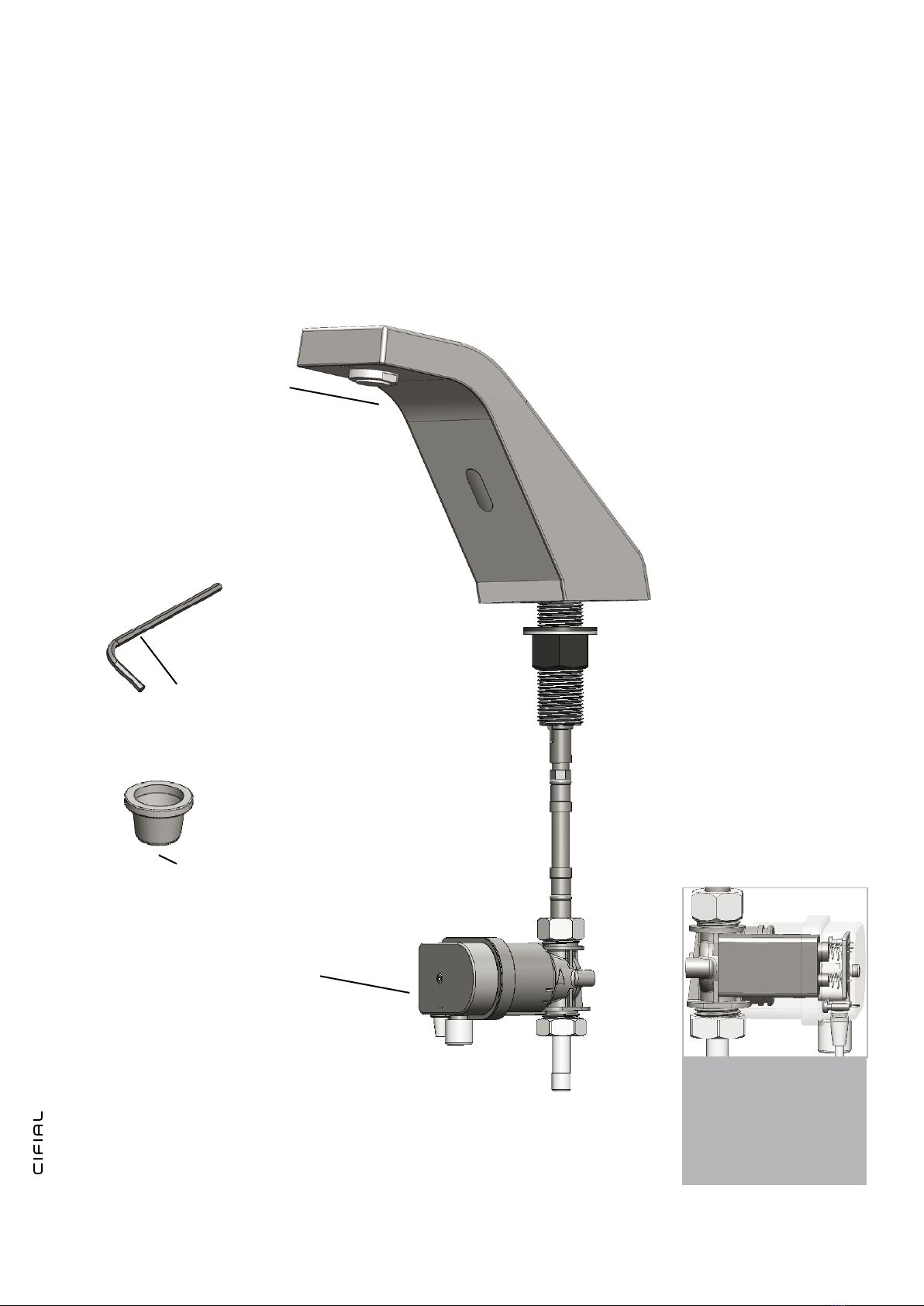
CONTEÚDO DO PACK
PACK CONTENTS
1x Torneira e acessórios
1x Faucet and attachments
1x Central de alimentação com 2 entradas
1x Dual power input box
1x Chave sextavada 2,5mm
1x Allen key 2,5mm
1x Filtro
1x Filter
1x Central de alimentação
de dupla entrada com
pilha alcalina de 9V
1x Dual power input box
with 9V alkaline battery

5
Check contents
Separate all parts from the packaging and check each part
with the pack contents section.
Make sure all parts are accounted for before discarding any
packaging material.
If any parts are missing, do not attempt to install your electronic
faucet until you obtain the missing parts.
INFORMAÇÃO DE PRÉ-INSTALAÇÃO
PRE-INSTALLATION INFO
Verique o conteúdo
Separe todas as peças da embalagem e verique cada peça
com a lista de componentes da embalagem.
Certique-se de que todos os componentes necessários
estão presentes antes de desembalar.
Se faltar algum componente, não instale a torneira até ter
todos os componentes em falta.
Para evitar problemas de sinal reetido
To avoid reection problems
1) Não instale o sistema de frente a um espelho ou qualquer
outro sistema operado por um sensor de infravermelhos.
2) Para prevenir problemas reetivos, é recomendada uma
distancia mínima de 1.5 metros entre a torneira e outro
objeto.
1) Do not install facing a mirror or any other electronic
system operated by an infrared sensor.
2) To prevent reection problems, it is recommended to
keep a minimum distance of 1.5 meters between the faucet
and any other objects.
Preparação para instalação
Vericar se todas ligações estão devidamente limpas. Não devem
existir sujidades, ta de teon ou partículas metálicas que possam
entrar na torneira. Risco de obstruir a saída da água.
Feche fornecimento de água.
Importante
Todas as canalizações devem estar de acordo com as normas
e regulações.
Preparation for installation
Flush water supply lines thoroughly before installing the faucet.
Do not allow dirt, Teon tape or metal particles to enter the
faucet.
Shut off water supply.
Important
All plumbing is to be installed in accordance with applicable
codes and regulations.

6
INSTALAÇÃO
INSTALLATION
PASSO 1 – Preparação para a instalação da torneira
1. Feche o fornecimento de água.
STEP 1 - Preparation for mounting the faucet
1. Shut off the water supply.
2. Desconecte o exível com a porca, a anilha metálica e a anilha
de borracha do nipple da torneira.
2. Disconnect the exible hose with the nut, washer and gasket
from the faucet nipple.
PASSO 2 – Instalação da torneira
1- Faça um furo no balcão ou lavatório
STEP 2 - Installing the faucet
1. Cut a hole in the deck or lavatory.
Anilha
Borracha Gasket
Anilha
metálica Washer
Porca Nut
.
.
7
2. Passe o exível com a porca, a anilha metálica e a anilha de
borracha no furo por baixo do balcão ou lavatório.
2. Pass the exible hose along with the nut, washer and gasket
through the hole in the deck or lavatory from below.
3. Conecte o exível ao nipple da torneira.
3. Connect the exible hose to the faucet nipple.
4. Posicione o corpo da torneira no furo do balcão ou lavatório.
4. Place the faucet body into the hole in the deck or lavatory.
Lavatório
Lavatory
Lavatory
Lavatório
Lavatório
Lavatory

8
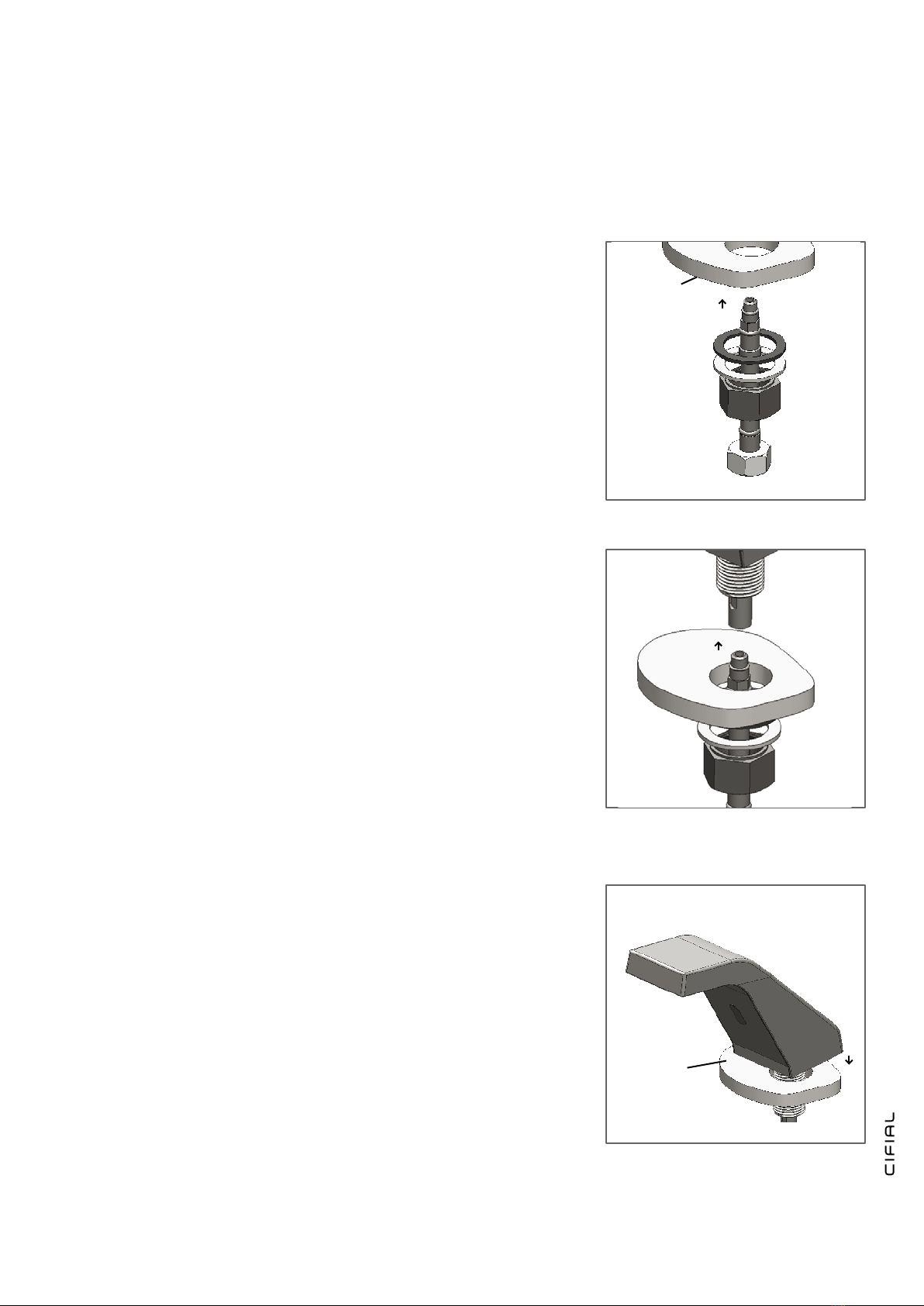
5. Deslize a anilha de borracha, a anilha metálica e a porca sobre o
corpo da torneira e xe-a.
(Nota) Tome atenção: o ressalto na porca tem que car orientado
para cima.
5. Slide the gasket, washer and nut over the faucet body nipple
and secure it.
(Note) Pay attention: the shoulder of the nut should be facing
up.
PASSO 3 – Ligação da fonte de alimentação
1. Ligue o exível que sai da base da torneira na ligação da válvula
solenóide da central de alimentação dupla.
(Nota) IMPORTANTE: A entrada e a saída são indicadas pela
seta no corpo da válvula selenoide.
STEP 3 - Connecting the water supply
1. Connect the exible hose coming from the faucet base to the
solenoid valve housing in the dual power input box.
(Note) IMPORTANT: Inlet and outlet should follow the indicating
arrow at the solenoid housing.
2. Se necessário, ligue o fornecimento de água na entrada da
válvula solenóide situada na central de alimentação com um exível
ou ligue directamente a válvula de corte.
(Nota) Certique-se que o ltro é instalado entre a válvula
solenóide na central de alimentação e a válvula de fecho.
(válvula com ângulo não fornecida)
2. If necessary, t the water supply to the inlet of the solenoid
valve located in the central supply with a exible or connect directly
to the shutoff valve.
(Note) Make sure that the lter is installed between the solenoid
valve housing in the dual power input box and the shut off
valve (angle valve not supplied).
Entrada de água
Water Inlet
Filter
Filtro

9
3. Ligue o fornecimento de água e verique a existência de fugas.
3. Turn on the water supply and check for leaks.
PASSO 4 – Ligação a fonte de alimentação.
1. Conecte o conector de 4 contactos que sai do corpo da torneira ao
conector que sai do corpo da central de alimentação.
IMPORTANTE: O conetor de 4 contactos deve ser conectado de forma
a não ser visível o O-ring branco e que se ouça o click do encaixe.
TENHA EM ATENÇÃO: Se o conetor de 4 contactos não car bem
ligado, a bomba funcionará continuamente.
STEP 4 - Connecting the power sorce
1. Connect the 4 contacts connector coming from the faucet body to the
one at the dual power input box.
IMPORTANT: the 4 contacts connector should be connected properly
so that the white o-ring is not visible and a clicking sound is heard.
PAY ATTENTION: If the 4 contacts connectors will not be connected
properly, the motor will work continuously.
2. O sensor vai entrar em modo de ajuste, aguarde 10 segundos
até poder utilizar o produto. Se o alcance não for satisfatório veja a
secção de ajustes.
2. In order to avoid entering into the adjusting mode, wait 10 seconds
before you will operate the system. If the range is unsatisfactory,
refer to the section titled “Settings adjustment”.
O-ring visível – mal conectado
O-ring visible - not connected properly
Ligação correta, apenas cam visíveis as
pregas do conetor
Connected properly so that only the groves
are visible
ABOUT 10 SECONDS

10
NOTA: Esta torneira esta equipada com um emulsor especial que
lhe permite ajustar a direção do uxo de água no local, a m de
evitar salpicos de água, se necessário. Para alterar o ângulo do
uxo de água, movimente simplesmente o emulsor de inclinação
regulável, pressionando-o suavemente.
NOTE: This faucet includes a special aerator that allows you to
adjust the water stream direction on site in order to prevent water
splashing if needed. To change the angle of the water stream,
simply move the adjustable tilting plate by pressing it smoothly.

11
AJUSTE CONFIGURAÇÕES
RANGE ADJUSTMENT
Adjusting the sensor range:
1. Shut off the water supply
2. Disconnect the power supply, battery or transformer from the
sensor.
3. Make a short circuit between the (+) and the (-) of the sensor.
You can use a screw driver or another conductor material to make
this short circuit. Alternatively, after disconnecting the power supply,
activate the sensor three or four times.
Do not make a short circuit on the power supply or on the
sensor when the power supply is connected to the sensor.
4. Reconnect the power supply to the sensor.
5. To enter into the adjusting mode, you have to put your hand in
front of the sensor at a distance of 2” (50mm) to 4” (100mm) from
the sensor within 5 seconds from the reconnection of the power
supply.
Note: if you will not put your hand in front of the sensor after connecting
the power supply, the sensor will not enter into adjusting mode and
the previous adjustment will return.
6. When the sensor enters into adjusting mode and your hand is
in front of the sensor, a slow ashing of the red light in front of the
sensor will occur.
7. Keep your hand in front of the sensor until the slow ashing
changes to quick ashing. At this point, move your hand to the
required distance from the sensor and wait until the red light will
stop ashing.
8. When the red light has turned off, the sensor is adjusted to the
required distance.
9. Check the distance you have set and if it is not satisfactory,
repeat steps 1-7.
10. Turn on the water supply.
Regulação do alcance:
1. Feche o fornecimento de água.
2. Desligue a fonte de alimentação, (porta pilhas ou transformador)
do sensor.
3. Faça um curto-circuito entre o (+) e o (-) do sensor. Pode utilizar
uma chave de parafusos ou outro objeto condutor qualquer para
provocar o curto-circuito. Alternativamente, depois de desligar a
fonte de alimentação, ligue o sensor três ou quatro vezes.
Não faça o curto-circuito na fonte de alimentação ou no sensor
quando a fonte de alimentação está conectada ao sensor.
4. Volte a ligar a fonte de alimentação ao sensor.
5. Para executar o ajuste do sensor, você tem que colocar a mão
na frente do sensor a uma distância entre 50 mm (2”) e 100 mm
(4”) a partir do sensor dentro de 5 segundos após a ligação do
fornecimento de energia.
Nota: Se não colocar a mão em frente ao sensor depois de ligar a
fonte de alimentação, o sensor não vai entrar no modo de ajuste e
voltará ao ajuste anterior.
6. Quando o sensor entra no modo de ajuste e a sua mão está a
frente do sensor, irá surgir uma luz vermelha intermitente lenta na
frente do sensor.
7. Mantenha a sua mão na frente do sensor até que o intermitente
lento passe a intermitente rápido. Neste momento, mova a sua
mão para a distância pretendida do sensor e espere até que a luz
vermelha pare de piscar.
8. Quando a luz do sensor desligar, o sensor está regulado para a
distância pretendia.
9. Teste a distância que registou e se não estiver satisfeito, repita
os passos 1-7.
10. Ligue o fornecimento de água.

12
When the battery weakens, the red indicator light will blink at
a constant rate when the user’s hands are within the sensor
range. The battery must be replaced within two weeks.
The battery must be replaced within two weeks, as follows:
1 - Carefully open the dual power input box using the 2.5mm
Allen key provided.
2 - Remove the old battery.
3 - Replace the used battery with a new 9V battery (Lithium
battery is recommended).
4 - Close the box.
SUBSTITUIÇÃO DAS PILHAS
BATTERY REPLACEMENT
Quando as pilhas carem sem carga, a luz indicadora
vermelha piscará constantemente sempre que as mãos do
utilizador se aproximem do alcance do sensor.
A pilhas devem ser substituídas dentro de duas semanas.
Como substituir a pilha:
1- Cuidadosamente, abra a central de alimentação usando
a chave sextavada de 2.5mm fornecida.
2- Remova a pilha gasta.
3- Sunstitua por uma pilha 9V nova (pilha de Lítio recomen-
dada)
4- Feche a central de alimentação.
IMPORTANTE: As pilhas não devem ser colocadas no lixo domestico normal. Contacte a autoridade local para
informação ou deposite em contentor especico para reciclagem.
IMPORTANT: Spent batteries should not be disposed of with normal household waste. Contact your local authority
for information on waste disposal and recycling.

13
Instruções de limpeza dos ltros
Esta torneira está munida com um ltro em aço inox para prevenir
que pequenas partículas entrem no circuito. Se o uxo de
água diminuir, pode ser que o ltro esteja obstruído.
O ltro pode ser limpo da seguinte forma:
1- Desligar o fornecimento de água.
2- Desmonte o tubo de alimentação da água.
3- Remova o ltro e Limpe-o debaixo de água a correr.
4- Monte de novo os componentes.
5- Retome a ligação da água.
6- Verique que não há fugas.
MANUTENÇÃO
MAINTENANCE
Filters cleaning instructions
This faucet is provided with one / two stainless steel lter(s)
preventing foreign articles to enter the lines. If the water
ow has decreased, this can be because the lter(s) is/are
clogged.
The lter(s) can be cleaned as follows:
1. Shut-off the water supply.
2. Disconnect the exible pipe/s.
3. Remove the lter and wash it under running water.
4. Reassemble the parts.
5. Turn on the water supply.
6. Make sure that there is no water leakage.
Cuidado e limpeza de cromados e acabamentos especiais.
NÃO use esfregão de aço ou artigos de limpeza que contenham
álcool, ácidos, abrasivos ou semelhantes. O uso de quaisquer
produtos de limpeza, de manutenção ou substancias proibidas
podem danicar a superfície da torneira. Para a limpeza
da superfície da torneira use APENAS sabão e água, em
seguida seque com um pano limpo ou toalha. Quando zer
a limpeza dos azulejos das paredes, as torneiras devem ser
protegidas de qualquer projeção de produtos abrasivos.
Care and cleaning of chrome and special nishes.
DO NOT use steel wool or cleansing agents containing alcohol,
acid, abrasives, or the like. Use of any prohibited cleaning or
maintenance products or substances could damage the surface
of the faucet. For surface cleaning of faucet us ONLY soap
and water, then wipe dry with clean cloth or towel. When
cleaning bathroom tile, the faucets should be protected from
any splattering of harsh cleansers.

14
LISTA DE PEÇAS
SPARTE PARTS LIST
Kit de autocolantes e parafusos
Seals and Screws Kit
Kit do Sensor
Sensor Kit
Kit alojamento solenóide dupla alimentação
Solenoid Housing Dual Power Kit
Kit alojamento solenóide dupla alimentação USA
Solenoid Housing Dual Power Kit
Electrovalvula
Solenoid Valve Kit
Kit central de alimentação
Dual Power Cover Kit
Transformador
Transformer
07210105
07220153
07231011
07231012
07230018
07220080
06522047

15
RESOLUÇÃO DE PROBLEMAS
TROUBLESHOOTING
PROBLEMA INDICADOR CAUSA SOLUÇÃO
Não sai água na
torneira:
1- O sensor pisca
continuamente quando o
utilizador coloca as mãos
no alcance do sensor.
Pilhas sem carga. Substituir a pilha 9V.
2- A luz vermelha no
sensor não pisca quando o
utilizador coloca as mãos
no alcance do sensor.
1- Alcance muito curto.
2- Alcance muito longo.
3- Pilhas completamente esgotadas.
4- A unidade está em “Modo Segurança” *.
5- O sensor está com reexos do
lavatório ou outro objeto .
6- Os conectores entre a unidade elec-
trónica e a central de alimentação estão
desconectados ou conectados de forma
incorrecta.
Aumentar o alcance.
Diminuir o alcance.
A pilha 9V deve ser substituída.
Eliminar a causa do reexo.
Conecte os conectores de forma correcta. Veja como,
na pag. 9
3- A luz vermelha no
sensor pisca quando o
utilizador coloca as mãos
no alcance do sensor.
1- Detritos ou calcário no diafragma.
2- O orifício central do diafragma está
obstruído ou o diafragma está danicado.
3- A pressão da água está a cima dos
8 bar.
4- A pressão de fornecimento de água
é inferior a 8 bar e a pressão no corpo
da torneira é ainda maior. Esta situação
pode ser provocada por um aumento
súbito da pressão de alimentação de
água, que o anti retorno evita de diminuir
mesmo depois de a pressão do fornecimento
de água baixar dos 8 bar.
1- Desaparafuse a solenóide, extraia o pistão e a
mola da solenóide e limpe-os. Use um removedor de
calcário se necessário. Quando substituir o pistão,
tenha a certeza que a mola ca na posição vertical.
2- Limpe o orifício ou substitua o diafragma.
3- Reduza a pressão da água.
4- Feche o fornecimento de água e desenrosque um
dos exiveis de forma a reduzir a pressão que bloqueia
o produto.
O uxo de água que sai
da torneira não para:
1- O sensor pisca uma vez
quando o utilizador coloca as
mãos no alcance do sensor.
2- A luz vermelha no sen-
sor não pisca quando o
utilizador coloca as mãos
no alcance do sensor.
1- Detritos ou calcário no diafragma.
2- Os conectores entre a unidade electrónica
e a central de alimentação não estão
conectados de forma correcta.
1- O sensor está sujo ou coberto.**
2- O sensor está com reexo do lavatório
ou outro objeto.
Limpe o orifício ou substitua o diafragma.
Conecte os conectores de forma correcta. Veja como,
na pag. 9
Limpe ou elimine possíveis interferências.
Diminuir o alcance ou eliminar a causa do reexo.
Fluxo de água reduzido: O ltro ou o emulsor estão obstruídos. Retire, limpe e volte a instalar.
* Modo Segurança – Se o sensor está fechado por mais de 90 segundos, a torneira cará automaticamente sem uxo de
água. Para voltar ao funcionamento normal, remova qualquer bloqueio para restabelecer o funcionamento.
** Neste caso, o uxo de água vai parar de qualquer maneira devido ao tempo de segurança.

16
RESOLUÇÃO DE PROBLEMAS
TROUBLESHOOTING
PROBLEM INDICATOR CAUSE SOLUÇÕES
No water coming out
of the Faucet:
1.Sensor ashes continuously
when user’s hands are
within the sensor’s range.
Low battery. Replace battery.
2. Red light in the sensor
does not ash (once) when
user’s hands are within the
sensor range.
1. Range is too short.
2. Range is too long.
3. Battery is completely used up
4. Unit is in “Security Mode” *
5. Sensor is picking up reections from
the washbasin or another
object..
6. Connectors between the electronic
unit and the Dual power input box are
disconnected or not connected all the
way through.
Increase the range.
Decrease the range.
The battery must be replaced.
Eliminate cause of reection.
Connect the connectors all the
way through. Refer to page 9 to
see how.
3. Red light in the sensor
ashes once when user’s
hands are within the sensor
range.
1. Debris or scale in solenoid.
2. The central orice in the diaphragm
is clugged or the diaphragm is torn
3. The water supply pressure is higher
than 8 bar.
4. The water supply pressure is under 8
bars and yet the pressure in the faucet’s
body is higher. This situation could be
caused by a sudden increase in the water
supply pressure that the backcheck
prevents from dropping, even after water
supply pressure drops under 8 bars.
Unscrew solenoid, pull out the plunger and the spring
from the solenoid and clean them. Use scale remover
material if needed. When replacing the plunger, please
make sure that the spring is in vertical position.
Clean the orice or replace diaphragm.
Reduce the supply water
pressure.
Shut off water supply and
unscrew one of the exible pipes
in order to reduce the pressure
that blocks the product.
Water ow from spout
does not stop:
1. Sensor ashes once
when user’s hands are
within the sensor’s range.
2. Red light in the sensor
does not ash (once) when
user’s hands are within the
sensor’s range.
1. Debris or scale in diaphragm.
2. Connectors between the electronic
unit and the Dual power input box are
not connected all the way through.
1. Sensor is dirty or covered. **
2. Sensor is picking up reections from
the washbasin or another object.
Clean the orice or replace diaphragm.
Connect the connectors all the way through. Refer to
page 9 to see how.
Clean or eliminate case of interference.
Decrease the range or eliminate cause of reection.
Water ow diminished: Filter or aerator is clogged. Remove, clean, re-install.
* “Security Mode”: If the sensor is covered for more than 90 sec. the faucet will automatically shut off water ow. To return to
normal operation remove any blockage to re-establish operation.
** In this case, the water ow will stop anyway after 90 seconds because of the security time.
Table of contents
Other CIFIAL Plumbing Product manuals


Popular Plumbing Product manuals by other brands

Kraus
Kraus Crespo KPF-2720 installation manual

Aqua Environment Inc
Aqua Environment Inc 873-1500 Operation and maintenance instruction

Hans Grohe
Hans Grohe AXOR Starck 10006000 installation manual

Twyford
Twyford E11248WH Fitting instructions

Grohe
Grohe Atrio 19 287 manual

Stern
Stern VENUS 3002 Series Installation and maintenance guide


Sanela
Sanela SLUN 17 Mounting instructions

Viega
Viega 8650.1 Instructions for use

Glacier bay
Glacier bay 20173-0310H Use and care guide

Hans Grohe
Hans Grohe Raindance Select E 360 Showerpipe 27288000 Instructions for use

Medway
Medway Easy Toilet Riser quick guide

American Standard
American Standard Amarilis 3801.000.002 Specification sheet