CIM ME550 DOG TAG User manual

OPERATOR MANUAL
EN
ME550 DOG TAG
MO.ME550DT/EN/R4

ME550 DOG TAG
Serial number:
Year:
IMPORTANT:
MF GROUP Srl. cannot be held
responsible for any errors or damages
caused by the use of supplies or spare
parts not specifically approved or
guaranteed by MF Group –CIM division
Reproduction, Modification, complete or
partial translation of this manual is
strictly forbidden without prior written
approval of MF Group –CIM division
© Copyright 2020. All rights reserved
MF Group - CIM division
Via O. Serra, 2 - Calderara di Reno
40012 BOLOGNA –Italy
Tel +39 051 6465011
Fax +39 051 6465012
e-mail: info@cimitaly.it
Web site: http//www.cimitaly.it/

OPERATOR MANUAL
i
Table of contents
1. How to use the manual .................................................................................... 1
1.1 Importance of the manual................................................................................................................. 1
1.2 How to keep the manual ................................................................................................................... 1
1.3 How to consult the manual ............................................................................................................... 1
1.4 Symbol ............................................................................................................................................... 2
2. General information......................................................................................... 3
2.1 General features................................................................................................................................ 3
2.2 Main components of ME550 ............................................................................................................. 4
2.3 Operating principle of ME550 ........................................................................................................... 6
2.4 Electrical specifications ..................................................................................................................... 7
2.5 Rating of the equipment and applicable standards ........................................................................... 7
2.6 Terms of use....................................................................................................................................... 7
2.7 Dimensions and weight...................................................................................................................... 7
2.8 Productioncapacities......................................................................................................................... 7
2.9 Operating precautions and safety regulations.................................................................................. 9
2.10 Safety requirements ........................................................................................................................ 10
2.11 Operation in technician mode......................................................................................................... 11
2.12 Symbols present on the machine..................................................................................................... 12
2.13 RAEE regulation ............................................................................................................................... 13
2.14 Declaration of compliance............................................................................................................... 15
3. Unpacking...................................................................................................... 17
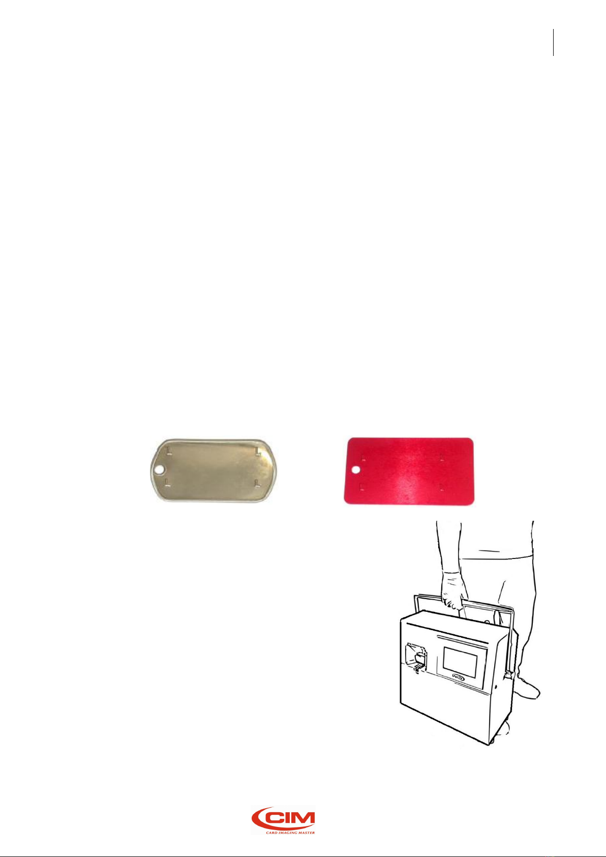
3.1 Unpacking ........................................................................................................................................ 17
4. Installation..................................................................................................... 20
4.1 Accessories check list....................................................................................................................... 20
4.2 Positioning the machine .................................................................................................................. 21
4.3 Removing mechanical locks and installing accessories................................................................... 21
4.4 Electrical connection ....................................................................................................................... 24
4.5 Connection to a computer............................................................................................................... 25
4.6 Warnings and installation precautions............................................................................................ 25
4.7 Power on and checking.................................................................................................................... 27
5. Human Machine Interface.............................................................................. 29
5.1 Introduction..................................................................................................................................... 29
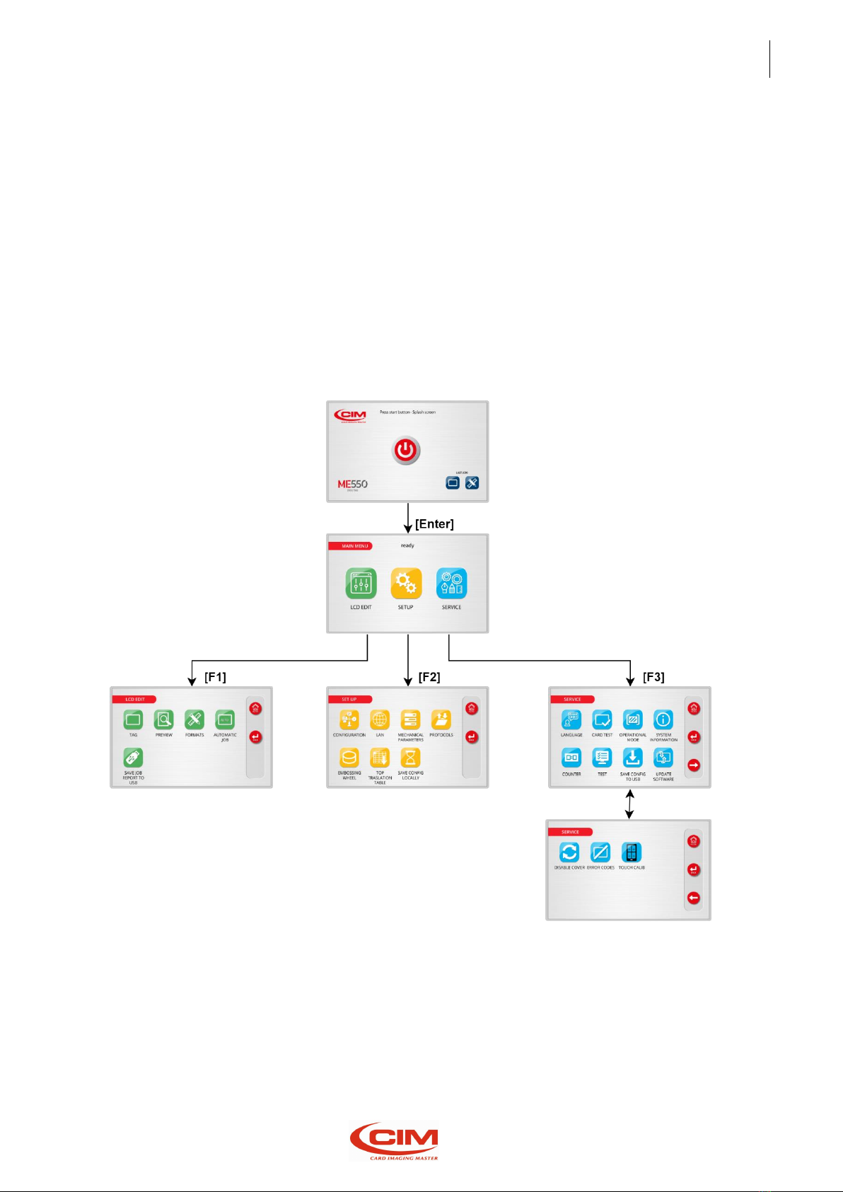
5.2 Main screen ..................................................................................................................................... 29
5.3 LCD Edit............................................................................................................................................ 31
5.3.1 Tag [F1] .....................................................................................................................................32
5.3.2 Preview [F2]..............................................................................................................................33
5.3.3 Formats [F3]..............................................................................................................................34
5.3.4 Automatic job [F4]....................................................................................................................38
5.3.5 Save job report to USB [F5] ......................................................................................................40
5.4 Setup................................................................................................................................................ 41
5.4.1 Configuration [F1].....................................................................................................................42
5.4.2 Lan [F2] .....................................................................................................................................43
5.4.3 Mechanical parameters [F3].....................................................................................................44

OPERATOR MANUAL
ii
5.4.4 Protocols [F4]............................................................................................................................46
5.4.5 Embossing wheel [F5]...............................................................................................................47
5.4.6 Top Translation Table [F6] ........................................................................................................49
5.4.7 Save config locally [F7] .............................................................................................................50
5.5 Service ............................................................................................................................................. 51
5.5.1 Language [F1] ...........................................................................................................................53
5.5.2 Card test [F2] ............................................................................................................................54
5.5.3 Operational mode [F3] .............................................................................................................54
5.5.4 System information [F4] ...........................................................................................................54
5.5.5 Counter [F5]..............................................................................................................................55
5.5.6 Test [F6] ....................................................................................................................................55
5.5.7 Save config to USB [F7].............................................................................................................56
5.5.8 Update software [F8]................................................................................................................56
5.5.9 Enable-Disable cover [F9] .........................................................................................................56
5.5.10 Error codes [F10] ......................................................................................................................57
5.5.11 Touch calibration [F11].............................................................................................................58
6. Tag production............................................................................................... 59
6.1 Tag production in STAND ALONE mode .......................................................................................... 59
6.2 Loading tag ...................................................................................................................................... 59
6.3 Format creation and fields definition.............................................................................................. 60
6.4 Entering data manually and embossing tag .................................................................................... 61
6.5 Loading data from data base and embossing tag............................................................................ 62
6.6 Tag printing...................................................................................................................................... 62
6.7 End of production cycle................................................................................................................... 63
7. Internet of Things........................................................................................... 64
7.1 FTP machine accessibility ................................................................................................................ 64
7.2 Remote access to User Interface thru Ethernet o Wi-Fi connectivity............................................. 64
7.3 Web Services availability ................................................................................................................. 64
7.3.1 Information...............................................................................................................................65
7.3.2 Network ....................................................................................................................................65
7.3.3 Date and time ...........................................................................................................................66
7.3.4 Update software.......................................................................................................................66
7.3.5 Users management...................................................................................................................66
8. Error message ................................................................................................ 67
8.1 Error messages and problem solving ............................................................................................... 67
8.2 Error codes table ............................................................................................................................. 67
9. Maintenance.................................................................................................. 68
9.1 Preventive maintenance performed by operator ........................................................................... 68

OPERATOR MANUAL
1. How to use the manual
1
1. How to use the manual
1.1 Importance of the manual
The present manual contains the instructions for the start-up, use and maintenance of the embosser
ME550 DOG TAG.
Before installing and starting up the machine it is necessary to read carefully all the instructions
contained here.
The effectiveness of the servicing strictly depends on properly and systematically following the
indications herein.
Please, remember that in case of problems or faults the TECHNICAL SUPPORT SERVICE of MF Group srl -
CIM division is always at your complete disposal for any explanation or assistance.
Therefore, MF Group srl - CIM division accept no responsibilities in case of wrong or inappropriate use.
MF Group srl - CIM division reserves the right to make changes at any time for the purpose of product
improvement without notice.
Make sure that any modification or updating of the Manual you receive is added to the text.
MF Group srl –CIM division is not liable for technical or editorial errors or omissions contained herein.
1.2 How to keep the manual
Do not remove, tear out or rewrite parts of the manual for any reasons. Keep the manual in a dry and
cool place.
1.3 How to consult the manual
This manual consists of:
•COVER WITH IDENTIFICATION OF THE GROUP THE EMBOSSERS BELONG TO
•TABLE OF CONTENTS
•INSTRUCTIONS AND/OR NOTES ON THE PRODUCT
By referring to the COVER you can identify the model of the embosser described in the manual.
Referring to the TABLE OF CONTENTS you can find the CHAPTERS and the PARAGRAPHS where you can
read all the notes regarding a given topic.
All INSTRUCTIONS AND/OR NOTES ON THE PRODUCT aim at identifying safety warnings, correct
procedures and operational qualifications required for a proper servicing of the embossers.
Moreover,we would like to underline that some images contained in the manual to make the
identification of the described parts easier might not look exactly as the embosser you purchased.

OPERATOR MANUAL
1. How to use the manual
2
1.4 Symbol
The symbols used in this manual to identify warnings and notifications relevant for safety and for the
proper use of the machine are described below. The same symbols can be present on the machine itself
to signal danger areas and to reference the corresponding safety notes contained in the manual.
MEANING OF THE SYMBOLS
GENERAL OPERATING NOTE: PAY
ATTENTION TO SYMBOLS AND TO THE
INSTRUCTIONS
CONTAINED IN THE TEXT
NEXT TO THEM
Prescription and Indication signs (rectangular shape): obligation to use the protections indicated on the
sign to carry out the operation described beside the symbol:
COMPULSORY HAND PROTECTION (GLOVES)
COMPULSORY EYE PROTECTION (GOGGLES)
PROTECT EARS BY WEARING THE SUITABLE EARMUFFS
Caution Signs-Danger Signs (triangular shape): situations of General Danger for the safety of the person
or the machine:
CAUTION! GENERAL DANGER
CAUTION! DANGEROUS VOLTAGE
CAUTION! HIGH TEMPERATUR
CAUTION! CRUSHING HAZARD
CAUTION! MACHINE MOVING COMPONENTS
INFORMATION

OPERATOR MANUAL
2. General information
3
2. General information
2.1 General features
METAL EMBOSSER 550, below referred to as ME550 DOG TAG, is an automatic system for the
customization of “Metal Plate”.
The main feature of the ME550 DOG TAG embosser is to produce plate in STAND-ALONE mode, that is
without the aid of a computer.
Data in CSV format can be uploaded using a USB Pen (FLASH PEN DRIVE) using the USB port located on
the back panel.
The STAND ALONE mode provides the possibility to enter data in two different ways:
- Touch screen LCD display (resolution 800x480)
- USB keyboard
ME550 DOG TAG can also be connected to a Computer with an USB port.
Moreover, protocol standards are available on the machine and make the ME550 DOG TAG system
versatile as it can be connected to several existing application packages.
ME550 DOG TAG embosses all plates’type “DOG TAG” (Fig. A) and Medical Red Alert Tag” (Fig. B).
Any other different usage of the embosser is not permitted.
The embosser can be easily carried. However, it weighs 26kg,
therefore it is necessary to be extremely careful when moving it.
It is advisable to take all necessary precautions regarding its
transportation, such as locking the clamps with the provided lock.
When the machine reaches its destination, it must be positioned
horizontally to operate and released from the locks.
Fig. A
Fig. B

OPERATOR MANUAL
2. General information
4
2.2 Main components of ME550
This paragraph shows the main components of the embosser ME500 and is useful for their
identification.
It is also meant as an instrument that allows the client to interface with our specialized technicians in
the most appropriate and suitable way.
MAIN COMPONENTS AND THEIR POSITION
1. X Axis clamp sliding
2. Drum-Embossing unit
3. Machine power supply unit
4. Removable tag feeder
5. Picking clamps

OPERATOR MANUAL
2. General information
5
ME550 DOG TAG console consists of an LCD touch panel.
The touch panel allows to view the operating state of the machine, the functions connected to the
plates’ production, the work settings and the machine settings.
It also displays different symbols, logos and fonts.
Thanks to the touch panel it is possible to access the various functions provided by the machine, such as
arranging tasks, setting the machine and checking its functionality.
It’s possible use an external keyboard to move through the screens.
In the bracket [...] is shown the function (F1; F2; ENTER; ESC; arrows; etc.) when an USB keyboard is
connected (optional)

OPERATOR MANUAL
2. General information
6
2.3 Operating principle of ME550
To produce a Plate, ME500 carries out a sequential cycle that can be briefly summarized in the following
stages:
•LOADING
•EMBOSSING
•UNLOADING
LOADING
The plate is ejected from the loader by the
thrust of a sprocket moved by the clamps
that takes it to the loading area.
When it reaches the aforementioned area,
the tag is picked up by the clamps.
EMBOSSING
After picking up the plate, the clamps
transport it to the printing area, placing it
under the drum and simultaneously
extracting another one.
At the same time the drum rotates, thus
taking the character to be embossed under
the stamp and starting the embossing cycle.
UNLOADING
When all the plate’s characters have been
embossed, the clamps move to the
unloading area and drop the plate into the
provided tray.
The unloading stage ends the operating
cycle of the plate.
IMPORTANT:
THE OPENING OF THE FRONT PANEL CAUSES THE
IMMEDIATE STOP OF THE MACHINE AND THE
INTERRUPTION OF ALL THE PROCESS IN PROGRESS.

OPERATOR MANUAL
2. General information
7
2.4 Electrical specifications
Power supply
100-240 Vac 50/60 Hz
Max Absorbed Current
1,50 A
Absorbed Power
120 W
Fuse (5x20 mm)
T 2A
Main controller
Coldfire 32-bit, 66 MHz BGA technology
PC interface
USB (cavo USB A - USB B)
Baud Rate
Programmable
Working Noise
Lower than 73 dB (A)
Display
Display Touch
2.5 Rating of the equipment and applicable standards
Category
II
Protection classification
IP 20
Applicable standards
UL60950-1
IEC 60950-1
IEC EN 55022
IEC EN 55024
IEC EN 61000-3-2
IEC EN 61000-3-3
2.6 Terms of use
Working temperature
+ 10° ÷ +35°
Humidity
20% ÷ 85%
Storage temperature
0 ÷ +50°
Altitude
1000 m
2.7 Dimensions and weight
Height
270 mm
Width
486 mm
Depth
495 mm
Weight
26 Kg
2.8 Production capacities
Tag size
28x50 mm (Dog Tag)
32x57 mm (Med. Alert Tag)
60x65 mm
Materials and Thicknesses
0.65÷0.75 mm Aluminum
0.65÷0.75 Stainless Steel
0.8 Stainless Steel Dog Tag

OPERATOR MANUAL
2. General information
8
Value referring to the center of the tags
Drum Capacity
Up to 60 Characters
Max punchable surface
Embossing is possible up to 3 mm from
the clamp with Dog Tag and Medical Alert Tag type
Embossing is possible up to 8 mm from the clamp with 60x65 Stainless Steel
tag with optional “REVERS HOLE”is possible to emboss until the lower
border of the tag.
Loading hopper capacity
130 Stainless Steel Dog Tag
140 Aluminum Medical Alert Tag
140 Stainless Steel 60x65 Tag
Productivity
5 lines x 9 characters up to 130 tags/hour, depending on the job.

OPERATOR MANUAL
2. General information
9
2.9 Operating precautions and safety regulations
The machine must be placed in a closed room, duly protected from dust and
excessive humidity. It should be positioned so that its distance from walls,
doors, windows, other machines or workstations allows to have immediate
access to its various parts in case of emergency, or to make the necessary
maintenance or repair work easier.
Do not install the machine near operating devices that produce dust, since the
dust might settle and accumulate inside the machine itself thus damaging the
internal electric devices.
Do not place the machine near a heat source, excessive cooling sources, water
sources, electromagnetic sources and smoke.
The machine must be placed on a top raised from the floor and properly
leveled at least at 60 cm height.
Do not run the machine in vertical position.
The machine is provided with special safety guards to prevent the operator
from coming in contact with the mechanical and electrical parts inside the
machine. Only specialized and authorized operators can access these parts for
maintenance and repairs. Simple general maintenance can be performed by
the operator without any risks of electrocution or other damages due to
mechanical devices, but it must be carried out after the machine has been
stopped and the power supply disconnected.
Do not tamper with the machine safety devices and do not modify them, even
partially.
The machine is made of flame-resistant materials in order to reduce the risk
of fire.
Moreover, it is fitted with a short circuit protection system that guarantees
the prompt isolation of the power supply.
Always make sure that the power cable is intact and has no cuts and cracks.
The presence of cuts or cracks might cause the user’s electrocution and might
create serious damages to the machine.
Do not place or drop liquids on the machine cover as it is not watertight.
It is particularly important to avoid any risk of oxidation that might cause wear
and tear and erosion to the mechanical parts.
The noise level produced by the machine is lower than 75 DB (measured at 1
m distance and at 1.60 m height from the floor).
The aforementioned value can be higher when special types of steel tags are
worked or if the machine is placed on a worktop that amplifies the noise or if
the machine has not been properly adjusted. If the operator is exposed every
day to a noise level probably higher than 85 DB, it is necessary to use ear
protection as provided for by standards 86/188/CEE

OPERATOR MANUAL
2. General information
10
2.10 Safety requirements
The Operator's Area of ME550 is compliant with all the safety requirements
set by the main European and non-European regulations.
Still, we suggest carefully reading the indications contained in the following
pages, where the symbols used in the Machine Operator Area, the possible
dangerous situations and the necessary precautions are described.
Dangerous mechanical parts (belts and pulley) - Risk of being crushed or
trapped.
Make sure you do not enter the working areas with your hands. Tie your
hair to avoid the risk of it being trapped in the machine.
For the same reason keep any hanging objects that you might wear such as
ties, necklaces, pendants or others away from the machine.
The machine is provided with mechanical protections (locks, screens, shields)
and software protection systems to stop immediately all the moving parts
when the front guard is opened. However, in case of damages to the safety
system the machine can work even with the cover open. in this case the
moving mechanical parts represent a potential danger for the operator's
safety. if the protection systems are damaged, switch off the machine and call
for technical support.
Warning: The machine can be started even with a remote control (Personal
Computer). When it is necessary to work on potentially dangerous parts
(removing stuck boards, resetting in case of errors or routine maintenance)
be extremely careful.
High voltage parts - Electrocution hazard
It is not possible to access any high voltage tension part from the Operator's
Area. All the high voltage circuits are positioned in closed areas and protected
by fixed shieldings.
To guarantee maximum safety the covers and all the accessible metal parts
are electrically grounded. Before putting the machine on the market, the
efficiency of the ground connection is checked on all the appliances by the
staff in charge of quality control.
It is forbidden to remove or modify in any way the external and internal guard
protections of the machine. Should it be necessary, please contact the
Technical Service of MF Group –CIM division.
The machine is provided with special safety protections to avoid the
operator to come in contact with its internal mechanical and electrical parts.
Access to these parts is permitted only to specialized staff in charge of
repairs and maintenance and especially authorized to carry out these tasks.
The simple maintenance can be safely carried out by the operator, as long as
the machine is stopped and disconnected from the power supply.

OPERATOR MANUAL
2. General information
11
MF Group srl - CIM division accepts no responsibility for the damages that
might be caused by non-respect of the above stated instructions. In case of
faulty operation please contact the technical service.
The machine is provided with labels signaling possible danger areas. Their
meaning is described in the following paragraph
MF Group CIM division cannot be held responsible for the
consequences of
not abiding by these rules for the use of the
machine. In case of breakdown
call technical service.
2.11 Operation in technician mode
The authorized technical staff can temporarily disable the safety system associated to the "cover open"
thus allowing the use of the machine when protections are not active (menu SERVICE - DISABLE COVER,
protected by a password).
CAUTION! DO NOT USE THE MACHINE IN TECHNICIAN MODE UNLESS SPECIFICALLY AUTHORIZED BY
MF Group –CIM division. MODE RESERVED TO EXPERIENCED AND AUTHORIZED USERS.
Take the necessary precautions to make sure that the password that allows to disable the safety devices
is not given to non-qualified staff.
If you think that non-authorized people might know the password, modify it immediately (refer to the
technical manual or contact the technical staff of MF Group - CIM division).
MF Group –CIM division accepts no responsibility for any damages to people, property or animals due
to the non-respect of the above- stated precautions and particularly to the use of the machine with
protections disabled by non-authorized staff.
NEVER REMOVE OR MODIFY THE PROTECTIONS

OPERATOR MANUAL
2. General information
12
2.12 Symbols present on the machine
Some parts of the machine are covered with symbols on self-adhesive labels signalling their function and
dangerousness.
In this way the operator knows what kind of precautions to adopt and can consequently behave in the
most suitable way.
It is strictly forbidden to remove them.
BEWARE OF YOUR HANDS RISK OF BEING CRUSHED OF STRUCK
The machine in the wooden package weighs about 60 Kg, therefore it must be
moved by more than one person.
The net weight is 31 Kg. Be extremely careful when moving it.
CAUTION HIGH VOLTAGE
It is forbidden to carry out any work when the machine is under power. To
replace the mains fuse or to perform internal maintenance work remove the
main power cable and do not work on the socket.
ATTENTION MOVING COMPONENTS
In case of internal maintenance work the technician must disconnect the
power supply and work only when the machine has stopped.
ATTENTION GENERAL DANGER
The machine has various moving mechanical parts. Do not work inside and do
not remove the covers except for the front door used to load the plates
GROUNDED CONNECTION
Connection point of the protection grounded conductor.

OPERATOR MANUAL
2. General information
13
2.13 RAEE regulation
WEEE (Waste Electrical and Electronic Equipment) declaration
MF GROUP srl declare that its products comply with the European Directive 2012/19/EU on
waste electrical and electronic equipment, which purpose is the prevention of WEEE and the re-
use, recycling and other forms of recovery of wastes.
MF GROUP srl is registered, within the terms of the law, to the Italian WEEE Register with
the number A.E.E.è IT08020000003483 and fulfil the obligations of financing of WEEE
management by adhering to a collective funding system.
The symbol of the crossed-out wheeled bin on the product or on its packaging indicates that it
should not be disposed of as a household waste. Instead it shall be handed over to the
appropriate collection point for recycling of electrical and electronic equipment.
By ensuring the product is disposed of correctly, you will help prevent potential damage to the
environment and human health.
Inappropriate waste handling of the product could cause potential damage to the environment
and human health and involves the application of the administrative sanctions provided by
law.
For further detailed information about recycling of the product, please contact your local
council office, your household waste disposal service or the manufacturer of the product.

OPERATOR MANUAL
2. General information
14

OPERATOR MANUAL
2. General information
15
CB
2.14 Declaration of compliance
The manufacturer MF Group srl - CIM division - Via Serra, 2 - 40012 Calderara di Reno - Bologna –Italy,
declares under its sole responsibility that the embosser ME500 is compliant with the main
international
standards and particularly that:
ME500 complies with part 15
of FCC
rules, subchapters A
and B - sections
15.107 (b) (e)
and 15.109 (b) (g) -
concerning Class A digital devices.
The device complies with the
provisions
contained in part 15 of the FCC rules. Its
functioning
depends on the following two conditions:
(1)
This device cannot cause damaging interferences,
and
(2)
This device must allow prospective
interferences,
including those that might cause
undesired operation.
UL60950 Approval (Safety of
Information Technology
Equipment)
File No. E231519
The equipment complies with
the
following European
Directives:
2004/108/EC,
2006/42/EC, 2006/95/EC.
ME500 complies with the IEC
International Standards on Safety
of
Information Technology
Equipment, EN
60950-1:2006
and IEC 60950-1:2005
(modified)
Certificate N. NO50313/A1 dated
2008-12-
12
ME550 complies with all the requirements of China RoHS standards concerning
pollution caused by Electronic Information Products (SJ/T11363-2006, SJ/T11364-
2006, SJ/T11365-2006)
Part Name
Toxic or Harmful Substances or Elements

OPERATOR MANUAL
2. General information
16
Lead
(Pb)
Mercury
(Hg)
Cadmium
(Cd)
Hexavalent
Chromium
(Cr VI)
Polybrominated
biphenyls (PBB)
Polybrominated
Diphenyl Ethers
(PBDE)
ME550
O
O
O
O
O
O
O: indicates that this toxic or harmful substance contained in all homogeneous materials used for this
part
is below the limit set by the provision SJ/T11363-2006.
X: indicates that this toxic or harmful substance contained in at least one of the homogeneous
materials
used for this part is above the limit set by the provision SJ/T11363-2006.
Contact directly MF Group –CIM division to obtain a copy of the original declarations of compliance
Other manuals for ME550 DOG TAG
1
This manual suits for next models
1
Table of contents