CIM ME2000S User manual

OPERATOR MANUAL
EN
ME2000S
MO.ME2000S/EN/R1

ME
MEME
ME2000S
2000S2000S
2000S
Serial number:
Year:
IMPORTANT
IMPORTANTIMPORTANT
IMPORTANT
:
MF GROUP Srl.
cannot be held
responsible or any errors or damages
caused by the use o supplies or spare
parts not speci ically approved or
guaranteed by MF Group – CIM division
Reproduction, Modi ication, complete or
partial translation o this manual is
strictly orbidden without prior written
approval o MF Group – CIM division
© Copyright 2020. All rights reserved
MF Group - CIM division
Via O. Serra, 2 - Calderara di Reno
40012 BOLOGNA – Italy
Tel +39 051 6465011
Fax +39 051 6465012
e-mail: in [email protected]
Web site: http//www.cimitaly.it/

OPERATOR MANUAL
i
Table of ontents
1.
How to use the manual .................................................................................... 1
1.1 Importance o the manual ................................................................................................................. 1
1.2 How to keep the manual ................................................................................................................... 1
1.3 How to consult the manual ............................................................................................................... 1
1.4 Symbol ............................................................................................................................................... 2
2.
General information......................................................................................... 3
2.1 General eatures ................................................................................................................................ 3
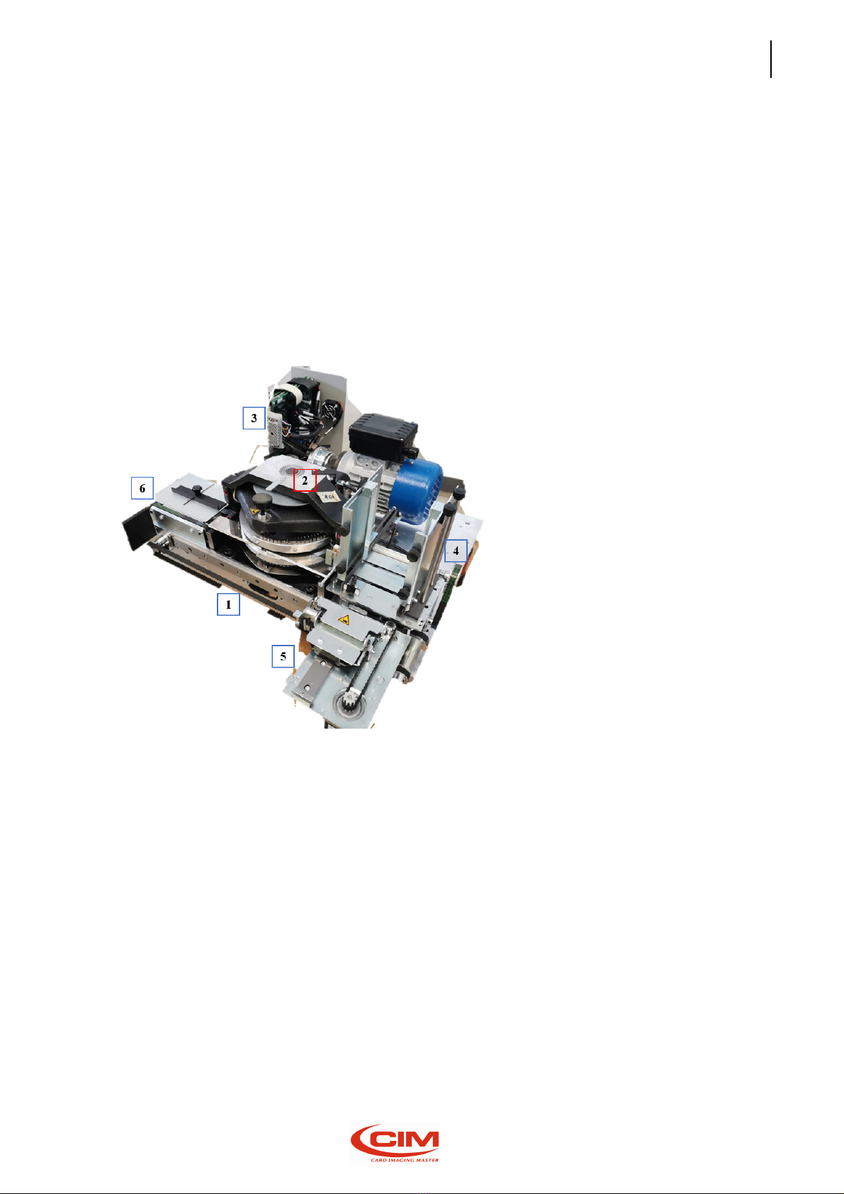
2.2 Main components o ME2000S ......................................................................................................... 4
2.3 Operating principle o ME2000S ....................................................................................................... 6
2.4 Electrical speci ications .............................................................. Errore. Il segnalibro non è definito.
2.5 Rating o the equipment and applicable standards .................... Errore. Il segnalibro non è definito.
2.6 Physical environment and operating conditions ........................ Errore. Il segnalibro non è definito.
2.7 Communication and so tware ........................................................................................................... 7
2.8 Plate; eeder and marking ................................................................................................................. 8
2.9 Intended use and limits ..................................................................................................................... 8
2.10 Residual risks ..................................................................................................................................... 9
2.11 Operating precautions and sa ety regulations ................................................................................ 10
2.12 Sa ety requirements ........................................................................................................................ 11
2.13 Operation in technician mode ......................................................................................................... 12
2.14 Symbols present on the machine ..................................................................................................... 13
2.15 RAEE regulation ............................................................................................................................... 14
2.16 Declaration o “CE” Con ormity ....................................................................................................... 15
2.17 Declaration o compliance ............................................................................................................... 16
3.
Unpa king ...................................................................................................... 17
3.1 Unpacking ........................................................................................................................................ 17
4.
Installation ..................................................................................................... 19
4.1 Accessories check list....................................................................................................................... 19
4.2 Positioning the machine .................................................................................................................. 20
4.3 Electrical connection ....................................................................................................................... 21
4.4 Connection to a computer ............................................................................................................... 21
4.5 Warnings and installation precautions ............................................................................................ 22
4.6 Power on and checking.................................................................................................................... 23
5.
Human Ma hine Interfa e .............................................................................. 25
5.1 Introduction ..................................................................................................................................... 25
5.2 Main screen ..................................................................................................................................... 25
5.3 LCD Edit ............................................................................................................................................ 27
5.3.1 Tag [F1] ..................................................................................................................................... 28
5.3.2 Preview [F2] .............................................................................................................................. 29
5.3.3 Formats [F3] .............................................................................................................................. 30
5.3.4 Automatic job [F4] .................................................................................................................... 34
5.3.5 Save job report to USB [F5] ...................................................................................................... 36
5.4 Setup ................................................................................................................................................ 37
5.4.1 Con iguration [F1] ..................................................................................................................... 38
5.4.2 Lan [F2] ..................................................................................................................................... 39

OPERATOR MANUAL
ii
5.4.3 Mechanical parameters [F3] ..................................................................................................... 40
5.4.4 Protocols [F4] ............................................................................................................................ 41
5.4.5 Embossing wheel [F5] ............................................................................................................... 42
5.4.6 Tag Types [F6] ........................................................................................................................... 44
5.4.7 Top Translation Table [F7] ........................................................................................................ 44
5.4.8 Save con ig locally [F8] ............................................................................................................. 46
5.5 Service ............................................................................................................................................. 47
5.5.1 Language [F1] ........................................................................................................................... 49
5.5.2 Card test [F2] ............................................................................................................................ 50
5.5.3 Operational mode [F3] ............................................................................................................. 50
5.5.4 System in ormation [F4] ........................................................................................................... 50
5.5.5 Counter [F5] .............................................................................................................................. 51
5.5.6 Test [F6] .................................................................................................................................... 51
5.5.7 Save con ig to USB [F7] ............................................................................................................. 52
5.5.8 Update so tware [F8] ................................................................................................................ 52
5.5.9 Enable-Disable cover [F9] ......................................................................................................... 52
5.5.10 Error codes [F10] ...................................................................................................................... 53
5.5.11 Touch calibration [F11] ............................................................................................................. 54
6.
Initial setting .................................................................................................. 55
6.1 Loader adjustment .......................................................................................................................... 56
6.2 Unloader adjustment ....................................................................................................................... 57
6.2.1 Unloader ejector adjustment ................................................................................................... 57
6.2.2 Unloader li t adjustment .......................................................................................................... 57
6.3 Embossing pressure adjustment ..................................................................................................... 58
7.
Internet of Things ........................................................................................... 59
7.1 FTP machine accessibility ................................................................................................................ 59
7.2 Remote access to User Inter ace thru Ethernet o Wi-Fi connectivity ............................................. 59
7.3 Web Services availability ................................................................................................................. 59
7.3.1 In ormation ............................................................................................................................... 60
7.3.2 Network .................................................................................................................................... 60
7.3.3 Date and time ........................................................................................................................... 61
7.3.4 Update so tware ....................................................................................................................... 61
7.3.5 Users management ................................................................................................................... 61
8.
Error message ................................................................................................ 62
8.1 Error messages and problem solving ............................................................................................... 62
8.2 Error codes table ............................................................................................................................. 62
9.
Maintenan e .................................................................................................. 64
9.1 Preventive maintenance per ormed by operator ........................................................................... 64

OPERATOR MANUAL
1.
How to use the manual
1
1. How to use the manual
1.1 Importan e of the manual
The present manual contains the instructions or the start-up, use and maintenance o the embosser
ME2000S.
Be ore installing and starting up the machine it is necessary to read care ully all the instructions
contained here.
The e ectiveness o the servicing strictly depends on properly and systematically ollowing the
indications herein.
Please, remember that in case o problems or aults the TECHNICAL SUPPORT SERVICE o MF Group srl -
CIM division is always at your complete disposal or any explanation or assistance.
There ore, MF Group srl - CIM division accept no responsibilities in case o wrong or inappropriate use.
MF Group srl - CIM division reserves the right to make changes at any time or the purpose o product
improvement without notice.
Make sure that any modi ication or updating o the Manual you receive is added to the text.
MF Group srl – CIM division is not liable or technical or editorial errors or omissions contained herein.
1.2 How to keep the manual
Do not remove, tear out or rewrite parts o the manual or any reasons. Keep the manual in a dry and
cool place.
1.3 How to onsult the manual
This manual consists o :
•COVER PAGE IDENTIFYING THE TYPE OF PRODUCT
•TABLE OF CONTENTS
•INSTRUCTIONS AND/OR NOTES ON THE PRODUCT
By re erring to the COVER you can identi y the model o the embosser described in the manual.
Re erring to the TABLE OF CONTENTS you can ind the CHAPTERS and the PARAGRAPHS where you can
read all the notes regarding a given topic.
All INSTRUCTIONS AND/OR NOTES ON THE PRODUCT aim at identi ying sa ety warnings, correct
procedures and operational quali ications required or a proper servicing o the embossers.
Moreover, we would like to underline that some images contained in the manual to make the
identi ication o the described parts easier might not look exactly as the embosser you purchased.

OPERATOR MANUAL
1.
How to use the manual
2
1.4 Symbol
The symbols used in this manual to identi y warnings and noti ications relevant or sa ety and or the
proper use o the machine are described below. The same symbols can be present on the machine itsel
to signal danger areas and to re erence the corresponding sa ety notes contained in the manual.
MEANING OF THE SYMBOLS
GENERAL
OPERATING
NOTE
:
PAY
ATTENTION
TO
SYMBOLS
AND
TO
THE
INSTRUCTIONS
CONTAINED IN THE TEXT
NEXT TO THEM
Prescription and Indication signs (rectangular shape): obligation to use the protections indicated on the
sign to carry out the operation described beside the symbol
:
COMPULSORY
HAND
PROTECTION
(GLOVES)
COMPULSORY EYE
PROTECTION (GOGGLES)
PROTECT EARS BY WEARING THE SUITABLE EARMUFF
S
Caution Signs-Danger Signs (triangular shape): situations o General Danger or the sa ety o the person
or the machine:
CAUTION!
GENERAL
DANGER
CAUTION!
DANGEROUS
VOLTAGE
CAUTION!
HIGH
TEMPERATUR
E
CAUTION
!
CRUSHIN
G
HAZARD
CAUTION
!
MACHIN
E
MOVING COMPONENTS
INFORMATION

OPERATOR MANUAL
2.
General in ormation
3
2. General information
2.1 General features
METAL EMBOSSER is an automatic eeder (METAL EMBOSSER 2000) embossing and punching machine
or metallic plates which use or the identi ication o industrial products. A small backup battery supplies
the charge or the memory thus permitting all in ormation to be saved and ready or subsequent use
even i the machine has been switched o .
The METAL EMBOSSER system consists in an embosser unit driven by a personal Computer (not
supplied) connected to a Computer with an USB port by means o the dedicated CIM so tware named
“PowerTag”.
The system may also run in o line mode (STAND-ALONE), without so tware, to acilitate setting
operations.
The STAND-ALONE mode provides the possibility to enter data in two di erent ways:
- Touch screen LCD display (resolution 800x480)
- USB keyboard
Any other di erent usage o the embosser is not permitted.

OPERATOR MANUAL
2.
General in ormation
4
2.2 Main omponents of ME2000S
This paragraph shows the main components o the embosser ME2000S and is use ul or their
identi ication.
It is also meant as an instrument that allows the client to inter ace with our specialized technicians in
the most appropriate and suitable way.
MAIN COMPONENTS AND THEIR POSITION
1.
X Axis clamp sliding
2. Drum-Embossing unit
3. Machine power supply unit
4. Tag eeder
5. Picking clamps
6. Tag exit

ME2000S console consists o
an LCD touch panel
The touch panel allows to view
the operating
plates’ production, the work
settings
It also displays di erent
symbols,
Thanks to the touch panel
it is possible to
arranging tasks, setting the
machine
It’s possible use an external keyboard to move through the screens
I
n the bracket [...] is shown the unction (F1; F2; ENTER; ESC; arrows; etc.) when an USB keyboard
connected (optional)
an LCD touch panel
.
the operating
state o the machine, the
unctions
settings
and the machine settings.
symbols,
logos and onts.
it is possible to
access the various unctions provided
by
machine
and checking its unctionality.
It’s possible use an external keyboard to move through the screens
.
n the bracket [...] is shown the unction (F1; F2; ENTER; ESC; arrows; etc.) when an USB keyboard
OPERATOR MANUAL
2.
General in ormation
5
unctions
connected to the
by
the machine, such as
n the bracket [...] is shown the unction (F1; F2; ENTER; ESC; arrows; etc.) when an USB keyboard
is

OPERATOR MANUAL
2.
General in ormation
6
2.3 Operating prin iple of ME2000S
To produce a Plate, ME2000S carries out a sequential cycle that can be brie ly summarized in the
ollowing stages:
•LOADING
•EMBOSSING
•UNLOADING
LOADING
The plate is ejected rom the loader by the
thrust o a sprocket moved by the clamps
that takes it to the loading area.
When it reaches the area, the tag is picked
up by the clamps.
EMBOSSING
A ter picking up the plate, the clamps
transport it to the printing area, placing it
under the drum and simultaneously
extracting another one.
At the same time the drum rotates, thus
taking the character to be embossed under
the stamp and starting the embossing cycle.
UNLOADING
When all the plate’s characters have been
embossed, the clamps move to the
unloading area and drop the plate into the
provided tray.
The unloading stage ends the operating
cycle o the plate.
IMPORTANT
:
THE OPENING OF THE FRONT PANEL CAUSES THE
IMMEDIATE STOP OF THE MACHINE AND THE
INTERRUPTION OF ALL THE PROCESS IN PROGRESS.

OPERATOR MANUAL
2.
General in ormation
7
2.4 Ele tri al spe ifi ations
Power
supply
100
Vac
± 10%
60
Hz or 230Vac
± 10%
50
Hz
Max
Absorbed
Current
8.0 – 4.0A max
Absorbed
Power
800 W
Fuse
(5x20
mm)
T
10A
Main
controller
CPU Arm Cortex
-
A8 / RAM 256 MB, with lash
-
disk and ile system
Linux O.S. based
Display
7
” color touchscreen display with high resolution
2.5 Rating of the equipment and appli able standards
Over voltage category (OVC)
II
Class
I
Protection
classi ication
IP X0
Pollution degree (PD)
2
Power Systems
TN
Protective
building installation
20A
Equipment mobility
Stationary
Applicable
standards
UL62368
-
1, 2
nd
Ed.
IEC
62368
-
1
IEC
EN
55032:2015
IEC
EN
55024:2010+A1:2014
IEC
EN
61000
-
3
-
2:2014
IEC EN 61000
-
3
-
3:2013
2.6 Physi al environment and operating onditions
Temperature
+5°C ÷ +40°C
Humidity
30% ÷ 90% not condensing
Max altitude
2000m
Transportation and storage temp
-
25°C ÷ +55°C
Working noise
Lower than 75 dB (A)
Environment
For indoor use only
2.7 Communi ation and software
Inter ace
USB 2.0 port (device
and host), Ethernet, WiFi
So tware
Linux based sel enclosed so tware PowerTag PC application
proprietary so tware Windows 7/8/10
Protocol
Multiembosser Optional: Cim, Xon
-
Xo , Stored Format de ault,
Stored Format Selected and Pound-Pound
Data ormat
50 ields o 42 characters each (Variable, Fixed data, Counters, etc.)

OPERATOR MANUAL
2.
General in ormation
8
2.8 Plate; feeder and marking
Dimensions
Rectangular tag: 30 ÷ 115 x 21 ÷ 90 mm
-
1.8 ÷ 4.53 x 0.83 ÷ 3.54 in
(WxH) Round tag: Ø 38,10 mm - 0.5 in, dog tag: 52 x 29 mm - 2.05 x
1.14 in (WxH) Medical alert tag: 57 x 32 mm - 2.24 x 1.26 in (WxH)
Materials
Stainless steel, carbon steel, aluminium, copper and brass
Thickness
0,4 ÷ 0,9 mm
-
0.0157 ÷ 0.0354 inch
Input hopper
ME1000S: manual eed
-
Single Access Point
ME2000S: up to 250 plates capacity (0,4 mm - 0.0157 inch)
Output hopper
ME1000S: manual eed
ME2000S: up to 250 plates capacity Options: FIFO ( irst in – irst out)
technology or side eject
Technology
Embossing, Indent or Debossing
Wheel capacity
60 or 90 slots
-
45 slots
drum available or special applications
Type set
Many character con igurations available:
Embossing: Simplex 2, OCRB1, Block USA, Double Block, etc. - Height
3 ÷ 12 mm / 0.118 ÷ 0.472 inch
Indenting: Simplex1, Simplex 2, etc. - Height 1 ÷ 4 mm / 0.039 ÷
0.157 inch
Debossing: Elite Dog Tag
Per ormance
231 tags per hour based on 55 characters
2.9 Intended use and limits
This appliance must be used by instructed person only.
Instructed person is any person who have been instructed and trained by a skilled person, or who is
supervised by a skilled person, to identi y energy sources that may cause pain and to take precautions to
avoid unintentional contact with or exposure to those energy sources.
Skilled persons have training or experience in the equipment technology, particularly in knowing the
various energies and energy magnitudes used in the equipment and are able to take action or
protection rom injury rom those energies.
Equipment is not suitable or use in locations where children are likely to be present.
User can not have access to internal parts protected by shields secured by screws.

OPERATOR MANUAL
2.
General in ormation
9
2.10 Residual risks
Some accessible parts must be considered dangerous or the operator because moving parts can be
reached in case o ault o the top door sensor. In order to avoid pain or injury, operator shall be
in ormed about moving parts that require attention, so that he may keep hands and any parts o the
body away rom dangerous zone:
WARNING: Hazardous Moving Parts. Keep body parts out o the motion path.

2.11 O
perating pre autions and safety regulations
The machine must be placed in a closed room, duly protected rom dust and
excessive humidity. It should be positioned so that its distance rom walls,
doors, windows, other machines or works
access to its various parts in case o emergency, or to make the necessary
maintenance or repair work easier.
D
o not install the machine near operating
dust might settle and
internal electric devices.
Do not place the machine near a heat source, excessive cooling sources, water
sources, electromagnetic sources and smoke.
The machine must be placed on a top raised rom the
leveled at least at 60 cm height.
Do not run the machine in vertical position.
Th
e machine is provided with special sa ety guards t
rom coming in contact with the mechanical and electrical parts inside the
mach
ine. Only specialized and authorized operators can access these parts or
maintenance and repairs. Simple general maintenance can be per ormed by
the operator without any risks o electrocution or other damages due to
mechanical device
stopped and the power supply disconnected.
Do not tamper with the machine sa ety devices and do not modi y them, even
partially.
The machine is made o lame
o ire.
Moreover,
it is itted with a short circuit protection system that guarantees
the prompt isolation o the power supply.
Always make sure that the power cable is intact and has no cuts and cracks.
The presence o cuts or cracks might cause the user’s
create serious damages to the machine.
Do not place or drop liquids on the machine cover as it is not watertight.
It is particularly important to avoid any risk o oxidation that might cause wear
and tear and erosion
The
noise level produced by the machine is lower than 75 DB (measured at 1
m distance and at 1.60 m height rom the loor).
The a ore
mentioned value can be higher when special types o steel tags are
worked or i the machine is placed on
the machine has not been properly adjusted. I the operator is exposed every
day to a noise level probably higher than 85 DB, it is necessary to use ear
protection as provided or by standards 86/188/CEE
perating pre autions and safety regulations
The machine must be placed in a closed room, duly protected rom dust and
excessive humidity. It should be positioned so that its distance rom walls,
doors, windows, other machines or works
tations allows to have immediate
access to its various parts in case o emergency, or to make the necessary
maintenance or repair work easier.
o not install the machine near operating
devices
that produce dust, since the
dust might settle and
accumulate inside the machine itsel thus damaging the
internal electric devices.
Do not place the machine near a heat source, excessive cooling sources, water
sources, electromagnetic sources and smoke.
The machine must be placed on a top raised rom the
loor and properly
leveled at least at 60 cm height.
Do not run the machine in vertical position.
e machine is provided with special sa ety guards t
o
prevent the operator
rom coming in contact with the mechanical and electrical parts inside the
ine. Only specialized and authorized operators can access these parts or
maintenance and repairs. Simple general maintenance can be per ormed by
the operator without any risks o electrocution or other damages due to
mechanical device
s, but it must be car
ried out a ter the machine has been
stopped and the power supply disconnected.
Do not tamper with the machine sa ety devices and do not modi y them, even
The machine is made o lame
-
resistant materials in order to reduce the risk
it is itted with a short circuit protection system that guarantees
the prompt isolation o the power supply.
Always make sure that the power cable is intact and has no cuts and cracks.
The presence o cuts or cracks might cause the user’s
electrocution and might
create serious damages to the machine.
Do not place or drop liquids on the machine cover as it is not watertight.
It is particularly important to avoid any risk o oxidation that might cause wear
and tear and erosion
to the mechanical parts.
noise level produced by the machine is lower than 75 DB (measured at 1
m distance and at 1.60 m height rom the loor).
mentioned value can be higher when special types o steel tags are
worked or i the machine is placed on
a worktop that ampli ies the noise or i
the machine has not been properly adjusted. I the operator is exposed every
day to a noise level probably higher than 85 DB, it is necessary to use ear
protection as provided or by standards 86/188/CEE
OPERATOR MANUAL
2.
General in ormation
10
perating pre autions and safety regulations
The machine must be placed in a closed room, duly protected rom dust and
excessive humidity. It should be positioned so that its distance rom walls,
tations allows to have immediate
access to its various parts in case o emergency, or to make the necessary
that produce dust, since the
accumulate inside the machine itsel thus damaging the
Do not place the machine near a heat source, excessive cooling sources, water
loor and properly
prevent the operator
rom coming in contact with the mechanical and electrical parts inside the
ine. Only specialized and authorized operators can access these parts or
maintenance and repairs. Simple general maintenance can be per ormed by
the operator without any risks o electrocution or other damages due to
ried out a ter the machine has been
Do not tamper with the machine sa ety devices and do not modi y them, even
resistant materials in order to reduce the risk
it is itted with a short circuit protection system that guarantees
Always make sure that the power cable is intact and has no cuts and cracks.
electrocution and might
Do not place or drop liquids on the machine cover as it is not watertight.
It is particularly important to avoid any risk o oxidation that might cause wear
noise level produced by the machine is lower than 75 DB (measured at 1
mentioned value can be higher when special types o steel tags are
a worktop that ampli ies the noise or i
the machine has not been properly adjusted. I the operator is exposed every
day to a noise level probably higher than 85 DB, it is necessary to use ear

2.12 Safety
requirements
T
he Operator's Area o ME
set by the main European and non
Still, we suggest
care ully reading
pages, where the symbols used
dangerous situations and the necessary precautions are described.
Dangerous me hani al parts (belts and pulley)
trapped.
Make sure you do not enter the working areas with your
hair to avoid the risk of it being trapped in the ma hine.
For the same reason keep any hanging obje ts that you might wear su h as
ties, ne kla es, pendants or others away from the ma hine.
The machine is provided with mechanical protectio
and so tware protection systems to stop immediately all the moving parts
when the ront guard is opened. However, in case o damages to the sa ety
system the machine can work even with the cover open. in this case the
moving me
chanical parts represent a potential danger or the operator's
sa ety. i the protection systems are damaged, switch o the machine and call
or technical support.
Warning: The ma hine an be started even with a remote ontrol (Personal
Computer).
When
(removing stu k boards, resetting in ase of errors or routine maintenan e)
be extremely areful.
High voltage parts
It is not possible to access any high voltage tension part rom the Operator's
Area. All the high voltage circuits are positioned in closed areas and protected
by ixed shielding.
To guarantee maximum sa ety the covers and all the accessible metal parts
a
re electrically grounded. Be ore putting the machine on the market
e iciency o the ground connection is checked on all the appliances by the
sta in charge o quality control.
It is orbidden to remove or modi y in any way the external and interna
protections o the machine. Should it be necessary, please contact the
Technical Service o MF Group
The ma hine is provided with spe ial safety prote tions to avoid the
operator to ome in onta t with its internal me hani al
A ess to these parts is permitted only to spe ialized staff in harge of
repairs and maintenan e and espe ially authorized to arry out these tasks.
The simple maintenan e an be safely arried out by the operator
the ma
hine is stopped and dis onne ted from the power supply.
requirements
he Operator's Area o ME
2000S
is compliant with all the sa ety requirements
set by the main European and non
-European regulations.
care ully reading
the indications contained in the ollowing
pages, where the symbols used
in the Machine Operator Area, the possible
dangerous situations and the necessary precautions are described.
Dangerous me hani al parts (belts and pulley)
-
Risk of being rushed or
Make sure you do not enter the working areas with your
hands. Tie your
hair to avoid the risk of it being trapped in the ma hine.
For the same reason keep any hanging obje ts that you might wear su h as
ties, ne kla es, pendants or others away from the ma hine.
The machine is provided with mechanical protectio
ns (locks, screens, shields)
and so tware protection systems to stop immediately all the moving parts
when the ront guard is opened. However, in case o damages to the sa ety
system the machine can work even with the cover open. in this case the
chanical parts represent a potential danger or the operator's
sa ety. i the protection systems are damaged, switch o the machine and call
or technical support.
Warning: The ma hine an be started even with a remote ontrol (Personal
When
it is ne essary to work
on potentially dangerous parts
(removing stu k boards, resetting in ase of errors or routine maintenan e)
be extremely areful.
High voltage parts
-
Ele tro ution hazard
It is not possible to access any high voltage tension part rom the Operator's
Area. All the high voltage circuits are positioned in closed areas and protected
To guarantee maximum sa ety the covers and all the accessible metal parts
re electrically grounded. Be ore putting the machine on the market
e iciency o the ground connection is checked on all the appliances by the
sta in charge o quality control.
It is orbidden to remove or modi y in any way the external and interna
protections o the machine. Should it be necessary, please contact the
Technical Service o MF Group
– CIM division.
The ma hine is provided with spe ial safety prote tions to avoid the
operator to ome in onta t with its internal me hani al
and ele tri al parts.
A ess to these parts is permitted only to spe ialized staff in harge of
repairs and maintenan e and espe ially authorized to arry out these tasks.
The simple maintenan e an be safely arried out by the operator
hine is stopped and dis onne ted from the power supply.
OPERATOR MANUAL
2.
General in ormation
11
is compliant with all the sa ety requirements
the indications contained in the ollowing
in the Machine Operator Area, the possible
dangerous situations and the necessary precautions are described.
Risk of being rushed or
hands. Tie your
For the same reason keep any hanging obje ts that you might wear su h as
ns (locks, screens, shields)
and so tware protection systems to stop immediately all the moving parts
when the ront guard is opened. However, in case o damages to the sa ety
system the machine can work even with the cover open. in this case the
chanical parts represent a potential danger or the operator's
sa ety. i the protection systems are damaged, switch o the machine and call
Warning: The ma hine an be started even with a remote ontrol (Personal
on potentially dangerous parts
(removing stu k boards, resetting in ase of errors or routine maintenan e)
It is not possible to access any high voltage tension part rom the Operator's
Area. All the high voltage circuits are positioned in closed areas and protected
To guarantee maximum sa ety the covers and all the accessible metal parts
re electrically grounded. Be ore putting the machine on the market
, the
e iciency o the ground connection is checked on all the appliances by the
It is orbidden to remove or modi y in any way the external and interna
l guard
protections o the machine. Should it be necessary, please contact the
The ma hine is provided with spe ial safety prote tions to avoid the
and ele tri al parts.
A ess to these parts is permitted only to spe ialized staff in harge of
repairs and maintenan e and espe ially authorized to arry out these tasks.
The simple maintenan e an be safely arried out by the operator
, as long as
hine is stopped and dis onne ted from the power supply.

MF Group srl
-
CIM division accepts no responsibility or the damages that
might be caused by non
aulty operation please contact the technical service.
The machine is provided with labels
meaning is described in the ollowing paragraph
MF Group
CIM division
not abiding by
these
call technical
service
2.13 O
peration in te hni ian mode
The authorized technical sta can temporarily disable the sa ety system associated to the "cover open"
thus allowing the use o the machine when protections are not active (menu
protected by a password).
CAUTION! DO NOT USE THE MACHINE IN TECHNICIAN MODE UNLESS SPECIFICALLY AUTHORIZED BY
MF Group –
CIM division. MODE RESERVED TO EXPERIENCED AND AUTHORIZED USERS.
Take the necessary precautions to make sure
is not given to non-
quali ied sta .
I you think that non-
authorized people might know the password, modi y it immediately (re er to the
technical manual or contact the technical sta o MF Grou
MF Group –
CIM division accepts no responsibility or any damages to people, property or animals due
to the non-respect o the above
-
protections disabled by non-
authoriz
NEVER REMOVE OR MODIFY THE PROTECTIONS
CIM division accepts no responsibility or the damages that
might be caused by non
-
respect o the above stated instructions. In case o
aulty operation please contact the technical service.
The machine is provided with labels
signaling
possible danger areas. Their
meaning is described in the ollowing paragraph
CIM division
cannot be held responsible or the
consequences
these
rules or the use o the
machine. In case o
breakdown
service
.
peration in te hni ian mode
The authorized technical sta can temporarily disable the sa ety system associated to the "cover open"
thus allowing the use o the machine when protections are not active (menu
SERVICE
CAUTION! DO NOT USE THE MACHINE IN TECHNICIAN MODE UNLESS SPECIFICALLY AUTHORIZED BY
CIM division. MODE RESERVED TO EXPERIENCED AND AUTHORIZED USERS.
Take the necessary precautions to make sure
that the password that allows to disable the sa ety devices
quali ied sta .
authorized people might know the password, modi y it immediately (re er to the
technical manual or contact the technical sta o MF Grou
p - CIM division).
CIM division accepts no responsibility or any damages to people, property or animals due
-
stated precautions and particularly to the use o the machine with
authoriz
ed sta .
NEVER REMOVE OR MODIFY THE PROTECTIONS
OPERATOR MANUAL
2.
General in ormation
12
CIM division accepts no responsibility or the damages that
respect o the above stated instructions. In case o
possible danger areas. Their
consequences
o
breakdown
The authorized technical sta can temporarily disable the sa ety system associated to the "cover open"
SERVICE
- DISABLE COVER,
CAUTION! DO NOT USE THE MACHINE IN TECHNICIAN MODE UNLESS SPECIFICALLY AUTHORIZED BY
CIM division. MODE RESERVED TO EXPERIENCED AND AUTHORIZED USERS.
that the password that allows to disable the sa ety devices
authorized people might know the password, modi y it immediately (re er to the
CIM division accepts no responsibility or any damages to people, property or animals due
stated precautions and particularly to the use o the machine with

OPERATOR MANUAL
2.
General in ormation
13
2.14 Symbols present on the ma hine
Some parts o the machine are covered with symbols on sel -adhesive labels signalling their unction and
dangerousness.
In this way the operator knows what kind o precautions to adopt and can consequently behave in the
most suitable way.
It is strictly orbidden to remove them.
BEWARE OF YOUR HANDS RISK OF BEING CRUSHED OF STRUCK
The machine in the wooden package weighs about 60 Kg, there ore it must be
moved by more than one person.
The net weight is 31 Kg. Be extremely care ul when moving it.
C
AUTION HIGH VOLTAGE
It is orbidden to carry out any work when the machine is under power. To
replace the mains use or to per orm internal maintenance work remove the
main power cable and do not work on the socket.
ATTENTION MOVING COMPONENTS
In case o internal maintenance work the technician must disconnect the
power supply and work only when the machine has stopped.
ATTENTION GENERAL DANGER
The machine has various moving mechanical parts. Do not work inside and do
not remove the covers except or the ront door used to load the plates
GROUNDED CONNECTION
Connection point o the protection grounded conductor.

OPERATOR MANUAL
2.
General in ormation
14
2.15 RAEE regulation
WEEE (Waste Electrical and Electronic Equipment) declaration
MF GROUP srl declare that its products comply with the European Directive 2012/19/EU on
waste electrical and electronic equipment, which purpose is the prevention of WEEE and the re-
use, recycling and other forms of recovery of wastes.
MF GROUP srl is registered, within the terms of the law, to the Italian WEEE Register with
the number
A.E.E.è IT08020000003483
and fulfil the obligations of financing of WEEE
management by adhering to a collective funding system.
The symbol of the crossed-out wheeled bin on the product or on its packaging indicates that it
should not be disposed of as a household waste. Instead it shall be handed over to the
appropriate collection point for recycling of electrical and electronic equipment.
By ensuring the product is disposed of correctly, you will help prevent potential damage to the
environment and human health.
Inappropriate waste handling of the product could cause potential damage to the environment
and human health and involves the application of the administrative sanctions provided by
law.
For further detailed information about recycling of the product, please contact your local
council office, your household waste disposal service or the manufacturer of the product.

OPERATOR MANUAL
2.
General in ormation
15
2.16 De laration of “CE” Conformity

OPERATOR MANUAL
2.
General in ormation
16
CB
2.17 De laration of omplian e
The manu acturer MF Group srl - CIM division - Via Serra, 2 - 40012 Calderara di Reno - Bologna – Italy,
declares under its sole responsibility that the embosser ME2000S is compliant with the main
international
standards and particularly that:
ME2000S complies with part 15
of FCC
rules, subchapters A and
B - sections
15.107 (b) (e) and
15.109 (b) (g) -
concerning Class A digital devices.
The device complies with the
provisions
contained in part 15 of the FCC rules. Its
functioning
depends on the following two conditions:
(1)
This device cannot cause damaging interferences,
and
(2)
This device must allow prospective
interferences,
including those that might cause
undesired operation.
UL62368-1 2
nd
Ed.Approval (Safety
of Audio/Video, Information and
communication Technology
Equipment) File No.E203983.
The equipment complies with the
following European Directives:
2014/30/UE, 2014/35/UE, 2006/42/EC.
ME2000S complies with the IEC
International Standards on Safety
of electrical and electronic
equipment within the field of
information and communication
technology IEC 62368-1.
ME
2000S
complies with all the requirements o China RoHS
standards concerning
pollution caused by Electronic In ormation Products (SJ/T11363-2006, SJ/T11364-
2006, SJ/T11365-2006)
Part Name Toxic or Harmful Substances or Elements
Lead
(Pb)
Mercury
(Hg)
Cadmium
(Cd)
Hexavalent
Chromium
(Cr
VI)
Polybrominated
biphenyls (PBB)
Polybrominated
Diphenyl Ethers
(PBDE)
ME2000S O O O O O O
O: indicates that this toxic or harmful substance contained in all homogeneous materials used for this
part
is below the limit set by the provision SJ/T11363-2006.
X: indicates that this toxic or harmful substance contained in at least one of the homogeneous
materials
used for this part is above the limit set by the provision SJ/T11363-2006.
Contact directly MF Group – CIM division to obtain a copy o the original declarations o compliance
Table of contents
Other CIM Embosser manuals