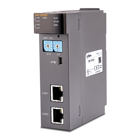
Cimon CM3 User manual

CM3 DIO Module
•
CM3-SP32EDO
•
CM3-SP32EOT
•
CM3-SP32EOC
•
CM3-SP16EOR
•
CM3-SP32EDT
•
CM3-SP16EDR
•
CM3-SP32EDOP
•
CM3-SP32EOTP
•
CM3-SP32EOCP
•
CM3-SP32EDTP
•
CM3-SP32EDCP
•
CM3-SP32PWM

- 2 -
Contents
Module List ………………………………………… 29
General Specifications …………………………… 30
Technical Specifications ………………………… 31
Wiring …………………………………………………… 32
Input/Output Type ………………………………… 36
Appearance and Dimensions ……………………… 37
Product Warranty ……………………………………43

- 3 -
Before You Start
This manual contains important information on the use and operation of this device. Please
read all the information carefully for optimal performance and to prevent any damage or misuse
of the device.
To keep products safe, all activities including product installation, wiring operation, and
maintenance are required to be treated by trained personnel.
Reproduction of contents, in whole or part of this manual, without written permission from
CIMON Inc. is prohibited.
Safety symbols are classified into two categories, “WARNING” and “CAUTION”.
Warning: This symbol describes situations that could cause major or fatal injury to the
user.
Caution: This symbol describes situations that may cause minor injury or damage to the
device.
SAFETY SYMBOLS USED IN THIS PRODUCT MEAN:
This symbol warns the user of potential hazards.
This symbol warns the user of uninsulated voltage within the unit that can cause
dangerous electric shock.
Keep this manual near the operating devices so it can be easily checked.

- 4 -
Design Precautions ( Warning)
Please install a safety circuit to protect the entire control system in case of an unexpected
power shutdown or PLC module malfunction. Such anomalies may severely compromise the
integrity of the overall system.
External to the PLC, please install circuits and switches to safeguard the system from
mechanical damages (ex. emergency stop, upper/lower limit switches, forward/reverse
direction interlocking circuits, etc)
When the PLC detects either of the following failure conditions, it may stop operation and turn
off all outputs.
- The overcurrent protection or overvoltage protection of the power supply module is
activated.
- The PLC CPU detected a failure, such as the watchdog timer error or module
installation failure, with its self-diagnostic function.
In addition, all outputs may be turned on when there is a failure that the PLC CPU cannot
detect, such as in the relay or TR terminal. Build an extra monitoring circuit that will monitor any
output signal that could cause serious accidents.
A greater than normal current passed through the PLC for an extended period of time, or a
short-circuited load flowing through the output module may cause a fire.
Build a circuit that turns on the external power supply after the PLC power supply is turned on.
If the external power supply is turned on first, it could result in output failure or malfunction.
In order to ensure that the system operates safely, please configure an interlock circuit in the
scan program for the following situations:
- When exchanging data with a computer or other devices.
- When operated by a computer or other devices.
Not doing so could result in output failure or malfunction.
Precautions for design ( Caution)
Do not bundle the input/output signal or communication cables with the main circuit and power
cables. They should be installed at least more than 100 mm (3.94 inches) apart. Not doing so
could result in output failure or malfunction.

- 5 -
Precautions for mounting ( Caution)
Use the PLC in an environment that meets the general specifications given in this manual.
Using this PLC in any environment outside the range of the general specifications could result
in electric shock, fire, malfunction, or damage to or deterioration of the product.
Please ensure that each module is installed correctly in its place. Loosely or incorrectly
installed pieces may result in malfunction, failure, or free-fall.
The PLC power supply should be turned off before mounting the module. Not doing so could
cause an electric shock or damage to the device.
Install I/O devices or extension connectors correctly. If they are installed incorrectly, it may
result in an input or output failure.
Do not convey direct vibration into the PLC. Doing so could cause electric shock, fire or
malfunctions.
After wiring work, please make sure to close the terminal cover before turning on the power for
the PLC system.
Precautions for wiring ( Warning)
Make sure to check the device’s rated voltage and circuit arrangement before wiring. Failure to
do so may cause electric shock or damage to the device.
Make sure to close the terminal cover before turning on the power of the PLC system after
wiring work. Failure to do so may cause electric shock.
Precautions for wiring ( Caution)
Make sure to check the device’s regular voltage and sequence of terminals. Failure to do so
may cause fire, electric shock and malfunctions.
When grounding the FG ground terminals, be sure to conduct the product with at least D type
(Class 3) grounding. Not doing so could result in electric shock or malfunctions.
When wiring, make sure that wiring debris does not enter the module. Failure to do so may
cause fire, equipment damage or malfunctions.

- 6 -
Precautions for wiring of Digital Input/Output Module ( Caution)
Select a cable considering ambient temperature and allowable current AWG 22 (0.3 mm2) or
more is recommended.
If the wiring is too close to a heat-generating device or directly contacted with oil for long
periods of time it may cause a short circuit, breakdown or malfunction.
Precautions for test run and repair ( Warning)
Please do not touch the terminals when the power is on. Doing so could cause an electric
shock or malfunctions.
When cleaning or tightening the screws, turn off the power of the PLC and all other systems.
Failure to do so could cause an electric shock or malfunctions.
Do not charge, disassemble, heat up, short, or solder the battery. Doing so could cause the
battery to heat up, rupture, or ignite, thereby harming the user.
Precautions for test run and repair ( Caution)
Do not dissociate the PCB from the module’s casing or make any modifications to the device.
Doing so may cause fire, electric shock, or malfunction.
When mounting or separating the module, make sure to turn off power to the PLC and all other
devices. Failure to do so could cause an electric shock or malfunctions.
Use radio, walkie-talkie, or cellphone devices at least 30cm away from the PLC. Not doing so
could result in malfunction.
Precautions for disposal ( Caution)
When the product is disposed of, it should be done according to your country’s regulations for
similar types of industrial waste. Not doing so may cause an occurrence of toxic substances or
explosions.

- 7 -
Category Model Name I/O Points Detail
Input Module
CM3-SP32EDO DI-32 DI 32 points, DC 24 V
CM3-SP32EDOP DI-32 DI 32 points, DC 24 V
(Terminal Block Type)
Output Module
CM3-SP32EOT DO-32 DO 32 points, DC 24 V
(TR Sink)
CM3-SP32EOTP DO-32 DO 32 points, DC 24 V
(TR Sink, Terminal Block Type)
CM3-SP32EOC DO-32 DO 32 points. DC 24 V
(TR Source)
CM3-SP32EOCP DO-32 DO 32 points, DC 24 V
(TR Source, Terminal Block Type)
CM3-SP16EOR DO-16 DO 16 points
(Relay Output)
Input/Output
Module
CM3-SP32EDT DI-16
DO-16
DI 16 points, DO 16 points
(TR Sink)
CM3-SP32EDTP DI-16
DO-16
DI 16 points, DO 16 points
(TR Sink, Terminal Block Type)
CM3-SP32EDCP DI-16
DO-16
DI 16 points, DO 16 points
(TR Source, Terminal Block Type)
CM3-SP16EDR DI-8
DO-8
DI 8 points, DO 8 points
(Relay Output)
PWM
Output Module
CM3-SP32PWM
DO-32
(Including
PWM)
PWM Output-
12
DO 32 points. DC 24 V
(TR Source)
PWM Output 12 points
(Duty Cycle Guarantee:
1~4000 pps
Max. output frequency:
65 kpps
Duty Cycle Resolution: 1/1000)
PLC-S DIO Module List

- 8 -
Items Specification Standards
Ambient Temp. -10℃–65℃ -
Storage
Temp.
-25℃–80℃ -
Ambient
Humidity
5–95% RH, Not Condensed -
Storage
Humidity
5–95% RH, Not Condensed -
Vibration
For Discontinuous Vibration
IEC 61131-2
Frequency Acceleration Amplitude
Times
5 ≤ f < 9 Hz - 3.5 mm X,
Y, Z Each direction,
10 times
9 ≤ f ≤ 150 Hz
9.8 m/s
2
(1G) -
Continuous Vibration
Frequency Acceleration Amplitude
Times
5 ≤ f < 9 Hz - 1.75 mm X,
Y, Z Each direction,
10 times
9 ≤ f ≤ 150 Hz
4.9 m/s
2
(0.5G) -
Shock
Max. impact acceleration: 147 m/s2 (15G)
Authorized time: 11 ms
Pulse wave: Sign half-wave pulse (3 times each in X, Y, Z)
IEC 61131-2
Noise
Square Wave
Impulse
N
oise
±2 kV CIMON
Standard
Electrostatic
Discharge
Voltage: ±4 kV (contact), ±8 kV (air) IEC 61131-2
IEC 61000-4-2
Radiated
E
lectromagnetic
F
ield
N
oise
80–1000 MHz, 10 V/m IEC 61131-2
IEC 61000-4-3
Fast Transient
Burst Noise
Unit Power
Module
Digital I/O
(24 V or
more)
Digital I/O
(less than 24V)
Analog I/O
Comm. interface
IEC61131-2
IEC61000-4-4
Voltage
2 kV 2 kV 1 kV
Ambient
C
onditions
No corrosive gas or dust
Altitude
2,000 m or less
Pollution
Pollution Degree 2 or less
Cooling Type
Natural air cooling
General Specifications

- 9 -
Items DC Input Relay Output TR Output
Rated I/O Voltage DC 24 V AC 220 V / DC 24 V DC 12V / 24 V
Rated I/O Current 4mA 1 point 2 A
COM 5 A
1 point 0.2 A
COM 2 A
On Voltage/Current DC 19 V/3 mA - -
Off Voltage/Current DC 6 V/1 mA - -
Response
Time
Off → On 3 ms or less 10 ms or less 1 ms or less
On → Off 3 ms or less 5 ms or less 1 ms or less
Operation Indication LED will be ON when the input is ON
Insulation Type Photocoupler
insulation Relay insulation Photocoupler
insulation
Input Type Sink/Source - -
Output Type - Relay Sink/Source
Diagram
※ The relay output must be less than 32 points per station.
※ Max. expansion number of CM3-SP16EOR is up to 2 modules.
※ Max. expansion number of CM3-SP16EDR is up to 4 modules.
Items PWM Output(SP32PWM)
Frequency Range
(Guarantee DUTY Ratio) 1 pps–4000 pps
Max Frequency 65 kpps
DUTY Ratio Resolution 0.0–100.0% (resolution 1/1000)
RAMP Control Frequency RAMP, DUTY ratio RAMP control
Technical Specifications
Technical Specifications – SP32PWM

- 10 -
SP32EDT
SP16EOR
Wiring

- 11 -
SP32EDO SP32EOT SP32EOC
SP16EDR
Wiring

- 12 -
SP32EDOP SP32EOTP SP32EOCP
SP32EDTP SP32EDCP
Wiring

- 13 -
SP32PWM
PWM Output Points
* All the other points can be used as a normal output point.
Wiring

- 14 -
Sink Type
Source Type
Input / Output Type

- 15 -
▶SP32EOT ▶SP32EDO ▶SP32EOC ▶SP32PWM
▶SP16EDR ▶SP32EDT ▶SP16EOR
Appearance

- 16 -
▶SP32EOTP ▶SP32EOCP ▶SP32EDOP
▶SP32EDCP ▶SP32EDTP
Appearance

- 17 -
(Unit: mm)
Dimensions

- 18 -
(Unit: mm)
Dimensions

- 19 -
(Unit: mm)
Dimensions

- 20 -
MEMO
This manual suits for next models
12
Table of contents
Other Cimon Controllers manuals
Popular Controllers manuals by other brands
Zennio
Zennio MINiBOX 0-10V X3 user manual
elsner elektronik
elsner elektronik KNX K8 Installation and adjustment

Digital Equipment
Digital Equipment Pro-Face GLC2000 Series user manual
Art
Art Flystick3 quick guide
CADSBI
CADSBI motion SMART Operating and safety instructions
Niles
Niles VCS-2D-HP Installation & operating guide
