Cimon PLC Series User manual

- 1 -
Positioning
•
CM1-PS08N

- 2 -
Contents
General Specifications …………………………… 24
Performance Specifications …………………… 25
Module Features ………………………………… 27
Dimensions ………………………………………… 28
Name of Parts ……………………………………… 29
Recommended Operation Procedure ………… 30
Installations and parameter settings ………… 31
Product Warranty ………………………………… 32

- 3 -

- 4 -
Before You Start
This manual contains important information on the use and operation of this device. Please
read all the information carefully for optimal performance and to prevent any damage or
misuse of the device.
To keep products safe, all activities including product installation, wiring operation, and
maintenance are required to be treated by trained personnel.
Reproduction of contents, in whole or part of this manual, without written permission from
CIMON Inc. is prohibited.
Safety symbols are classified into two categories: “WARNING” and “CAUTION”.
Warning: This symbol describes situations that could cause major or fatal injury to the
user.
Caution: This symbol describes situations that may cause minor injury or damage to the
device.
SAFETY SYMBOLS USED IN THIS PRODUCT MEAN:
This symbol warns the user of potential hazards.
This symbol warns the user of uninsulated voltage within the unit that can cause
dangerous electric shock.
Keep this manual near the operating devices so it can be easily checked.

- 5 -
Design Precautions ( Warning)
Please install a safety circuit to protect the entire control system in case of an unexpected
power shutdown or PLC module malfunction. Such anomalies may severely compromise the
integrity of the overall system.
External to the PLC, please install circuits and switches to safeguard the system from
mechanical damages (ex. emergency stop, upper/lower limit switches, forward/reverse
direction interlocking circuits, etc).
When the PLC detects either of the following failure conditions, it may stop operation and
turn off all outputs.
- The overcurrent protection or overvoltage protection of the power supply module is
activated.
- The PLC CPU detected a failure, such as the watchdog timer error or module installation
failure, with its self-diagnostic function.
In addition, all outputs may be turned on when there is a failure that the PLC CPU cannot
detect, such as in the relay or TR terminal. Build an extra monitoring circuit that will monitor
any output signal that could cause serious accidents.
A greater than normal current passed through the PLC for an extended period of time, or a
short-circuited load flowing through the output module may cause a fire.
Build a circuit that turns on the external power supply after the PLC power supply is turned
on. If the external power supply is turned on first, it could result in output failure or
malfunction.
In order to ensure that the system operates safely, please configure an interlock circuit in the
scan program for the following situations:
- When exchanging data with a computer or other devices.
- When operated by a computer or other devices.
Not doing so could result in output failure or malfunction.
Precautions for design ( Caution)
Do not bundle the input/output signal or communication cables with the main circuit and
power cables. They should be installed at least more than 100 mm (3.94 inches) apart. Not
doing so could result in output failure or malfunction.

- 6 -
Precautions for mounting ( Caution)
Use the PLC in an environment that meets the general specifications given in this manual.
Using this PLC in any environment outside the range of the general specifications could
result in electric shock, fire, malfunction, or damage to or deterioration of the product.
Please ensure that each module is installed correctly in its place. Loosely or incorrectly
installed pieces may result in malfunction, failure, or free-fall.
The PLC power supply should be turned off before mounting the module. Not doing so could
cause an electric shock or damage to the device.
Install I/O devices or extension connectors correctly. If they are installed incorrectly, it may
result in an input or output failure.
Do not convey direct vibration into the PLC. Doing so could cause electric shock, fire or
malfunctions.
After wiring work, please make sure to close the terminal cover before turning on the power
for the PLC system.
Precautions for wiring ( Warning)
Make sure to check the device’s rated voltage and circuit arrangement before wiring. Failure
to do so may cause electric shock or damage to the device.
Make sure to close the terminal cover before turning on the power of the PLC system after
wiring work. Failure to do so may cause electric shock.
Precautions for wiring ( Caution)
Make sure to check device’s regular voltage and sequence of terminals. Failure to do so may
cause fire, electric shock and malfunctions.
Make sure to tighten the screws with standard torque. Loose connections may cause a short
circuit, fire or malfunctions.
When grounding the FG ground terminals, be sure to conduct the product with at least D
type (Class 3) grounding. Not doing so could result in electric shock or malfunctions.
When wiring, make sure that wiring debris does not enter the module. Failure to do so may
cause fire, equipment damage, or malfunctions.

- 7 -
Precautions for wiring of Analog Input Module ( Caution)
The maximum length for the connection cable between the module and driver is 100 m,
but we recommend the length should be as short as possible.
It is required to use separate cables for the connection between the PS08N and driver,
encoder input cable for the PS08N, and input cable for the servo driver to avoid surge
or induction noise generated from the alternating current.
Select a cable considering ambient temperature and allowable current. AWG 22 (0.3 mm2) or
more is recommended.
Do not use a cable when it is laying in oil or water. Do not perform wiring or any
operation with wet hands. A short circuit or an electric shock may occur, which can
cause injury or fire.
Before connecting the external contact signal to a servo driver, check the polarity.
In the case of wiring together with the high voltage cable or power line, malfunction or
breakdown may occur due to induction noise.
When wiring with pipes, pipe grounding is required.
For the communication cable between the PS08N and the driver, use STP CAT-5 or above
for the connection.
If a communication error occurs during operation of the PS08N, attach a ferrite core to the
communication cable to prevent noise.
Precautions for test run and repair ( Warning)
Please do not touch the terminals when the power is on. Doing so could cause an electric
shock or malfunctions.
When cleaning or tightening the screws, turn off the power of the PLC and all other systems.
Failure to do so could cause an electric shock or malfunctions.
Do not charge, disassemble, heat up, short, or solder the battery. Doing so could cause the
battery to heat up, rupture or ignite thereby harming the user.
Precautions for test run and repair ( Caution)
Do not dissociate the PCB from the module’s casing or make any modifications to the
device. Doing so may cause fire, electric shock, or malfunction.
When mounting or separating the module, make sure to turn off power to the PLC and all
other devices. Failure to do so could cause an electric shock or malfunctions.
Use radio, walkie-talkie, or cell phone devices at least 30cm away from the PLC. Not doing
so could result in malfunction.

- 8 -
Precautions for disposal ( Caution)
When the product is disposed of, it should be done according to your country’s regulations
for similar types of industrial waste. Not doing so may cause an occurrence of toxic
substances or explosions.
- 9 -
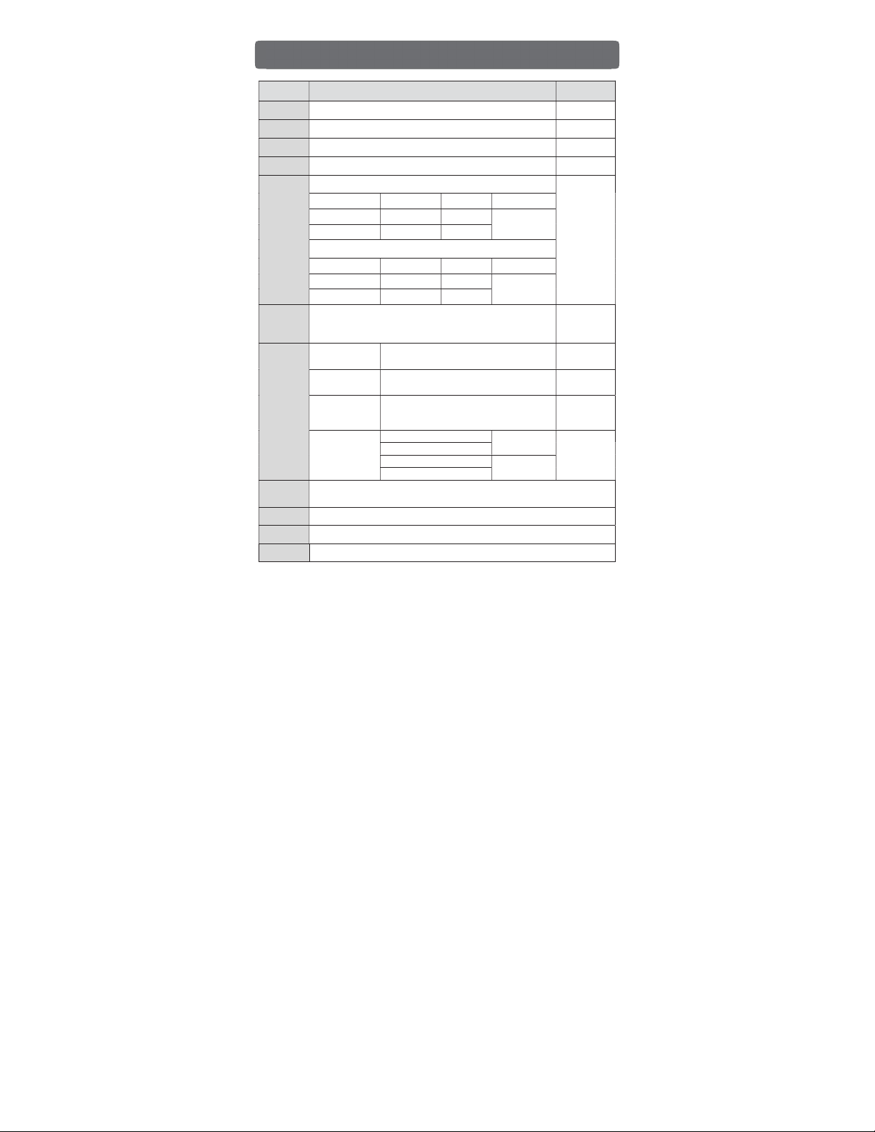
Items Specification Standards
Op. Temp
-10
℃
–65
℃
-
St. Temp
-25
℃
–
80
℃
-
Op. Hum 5
–
95% RH, Not condensed
-
St. Hum 5
–
95% RH, Not condensed
-
Vibration
In case of Intermittent Vibration
IEC 61131-2
Frequency Acceleration
Amplitude
Sweep
5 ≤ f < 9 Hz
-
3.5 mm
10 times
in X, Y, Z
9 ≤ f ≤ 150 Hz
9.8 m/s
2
(1G)
-
In case of Continuous Vibration
Frequency Acceleration
Amplitude
Sweep
5 ≤ f < 9 Hz
-
1.75 mm
10 times
in X, Y, Z
9 ≤ f ≤ 150 Hz
4.9 m/s2(0.5G)
-
Shock
Max. shock Acc.: 147
m/s
2
(15G)
Time: 11 ms
Pulse wave: Half sine wave pulse (3 times in X, Y, Z)
IEC 61131-2
Noise
Square Wave
Impulse Noise ±2 kV CIMON
Standard
Electrostatic
Discharge Voltage: ±4 kV (Contact discharge)
IEC 61131-2
IEC 61000-4-2
Radiated
E
lectromagnetic
Field
27
–
500 MHz,10 V/m
IEC 61131-2
IEC 61000-4-3
Fast Transient
Burst Noise
(Voltage)
CPU, Power 2 kV
IEC 61131-2
IEC 61000-4-4
Digital/Analog I/O (AC)
Digital/Analog I/O (DC) 1 kV
Communication
Ambient
Conditions
No corrosive gas and no dust
Altitude 2,000 m or less
Pollution Pollution Degree 2 or less
Cooling
Natural air cooling
General Specifications

- 10 -
Items Models
Number of
Controlled Axes 8 axes
Control Type Position control, Speed control, Linear interpolation,
Circular interpolation (*), Feed control
Control Units Pulse, mm, inch, degree
Position Data
Setting Configured by CICON (PLC Loader Program)
CM1-
CPU
Connect RS-232C or USB port, Via Communication module
Setting Data
Common, Basic, Expansion, Manual operation, Servo parameter
Operation data, Cam data, Command data (*)
Monitor Operation Data, Trace, Input terminal Data, Axis/Driver Error Data
Save Data Parameter, operation data saved in flash memory (without battery)
Func
tions
Positioning
Type Absolute Positioning/Incremental Positioning/Index Degree Positioning
Position
Command
Values
Absolute
Movements
Incremental
Movements
Interpolation
Movement
mm -2,147,483,648
–
2,147,483,647
inch -2,147,483,648
–
2,147,483,647
degree
Multi Rotary Coordinate system: -2,147,483,648
–
2,147,483,647
Single (1) Rotary Coordinate system (ABS): 0
–
359.9999
pulse
-2,147,483,648
–
2,147,483,647
Speed
Command
Values
mm 0
–
2,147,483,647 (mm/min)
inch 0
–
2,147,483,647 (inch/min)
degree
0
–
2,147,483,647 (degree/min)
pulse
0
–
2,147,483,647 (pulse/sec)
RPM 1
–
2,147,483,647 (RPM)
ACC/DEC
Type Trapezoidal type, S shape type
ACC/DEC
Time 1
–
65,535 ms, ACC pattern 4 types/DEC pattern 4 types (Select)
(*) Supported in F/W 2.0 and above versions.
Performance Specification (EtherCAT Positioning)

- 11 -
Items Models
Manual Operation Jogging/Inching
Homing Types Total 15 types supported by CiA402 Profile
Interpolation 2
–
8 axes linear interpolation, 2 axes circular interpolation (*),
3 axes Helical interpolation (*)
Velocity Unit Value/Percentage (%) (*)
Torque Units Percentage (%)
Absolute Position
S
ystem
Available (when using absolute encoder type servo driver)
Comm. Period 1
–
65,535 ms
Max. Distance Maximum distance 100 m between module and Servo Driver
Comm. Cable Over CAT.5 STP (Shielded Twisted pair) cable
Error Indicator LED on the module
Comm. Status
I
ndicator
LED on the module
IO Points 16 points (Input 16 points/Output 16 points)
Current
Consumption
136 mA
Weight 113.5 g
(*) Supported in F/W 2.0 and above versions.
Performance Specification (EtherCAT Positioning)

- 12 -
▶ Direct connection with the servo driver via EtherCAT
- The fast communication speed (1 ms
–
1000 ms)
- With Ethernet cable, wiring is very simple.
- Highly compatible with various brands of servo driver and motors.
- Set up servo parameter by CICON
- CICON software enables a user to conduct a trial run and program operation for
PS08N.
▶ PS08N follows the EtherCAT standard CiA402 profile specifications.
- PS08N supports EtherCAT Slave Servo Drives from other manufacturers.
- The EtherCAT Slave Servo Drives that have been tested for trial runs are listed in
the table below.
If you have drivers other than the listed below, please contact the distributor or
headquarters that you have purchased the drives from.
Manufacturers Drive Name
Omron R88D – KN01H – ECT
LS XDL – L7NA001B
▶ PS08N offers various functions required for positioning systems such as
positioning and speed control.
- Position control (Absolute, Incremental)
- Velocity control
- Multi axes control
- Interpolation control (Linear, Circular (F/W ver.2.0 or more), helical (F/W ver.2.0
or more))
▶ Switching control is easily done during the operation.
- Position / Velocity Control Switch
- Velocity / Position Control Switch
- Position / Torque Control Switch (F/W ver.2.0 or more)
▶ PS08N saves the parameters and operation data to memory.
(No batteries required)
▶ A user can implement an absolute positioning system.
CM1-PS08N Features

- 13 -

- 14 -
Unit: mm
Dimensions
- 15 -
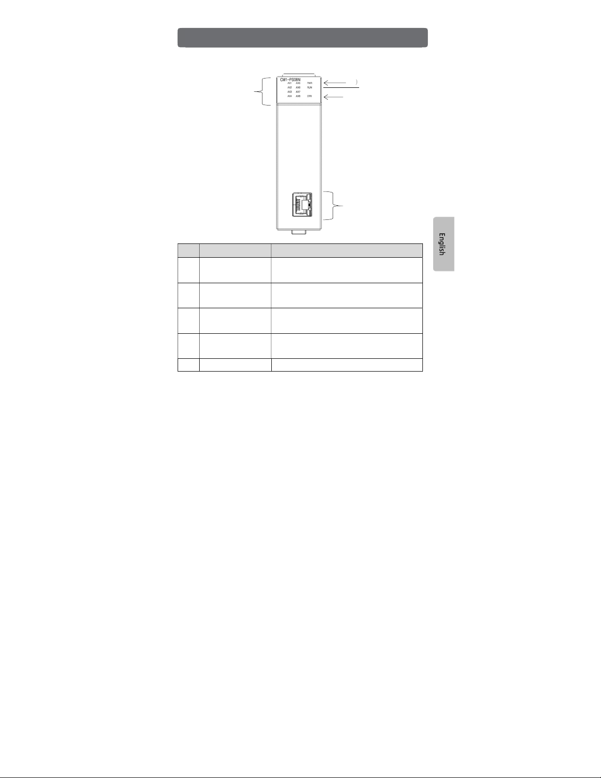
No Name Description
① Operation LED
ON: applicable axis is Enable
OFF: applicable axis is Disable
BLINK: applicable axis has error (2.5 Hz)
② Power LED
ON: CPU I/F is OK
OFF: Power is turned OFF
BLINK: CPU I/F has error (2.5 Hz)
③ Comm. status LED
ON: EtherCAT link is connected
OFF: EtherCAT link is disconnected
BLINK: Error status (2.5 Hz)
④ Error LED
ON: axis or servo driver has an error.
OFF: No error
BLINK: Error (2.5 Hz) or Warning (1 Hz)
⑤ RJ-45 connector Connector for servo driver
Name of parts
②
④
③
①
⑤

- 16 -
Recommended operation procedures

- 17 -
1. Connect EtherCAT cable between RJ-45 (OUT) of PS08N and the RJ-45 (IN) of
Servo driver.
2. Connect CICON to PS08N module.
3. Before use servo driver, check power, wiring and servo driver parameter.
4. Download parameter of PS08N Master setting to the PS08N module.
5. You can monitor the status of the axis after parameter download. If axis error occurs,
you can find out how to reset error when you double click the error code.
6. Make a program by CICON.
Installation and Parameter setting

- 18 -
All CIMON products including hardware, software, and firmware (collectively called
“Products”) carry a two-year warranty against defects in materials and workmanship
beginning from the date of product shipment from CIMON to its appointed distributor. If a
product proves defective in materials and workmanship within one year from the date of
purchase, we will replace or repair it. Products returned under warranty after 30 days
may be replaced with refurbished or remanufactured goods at CIMON’s discretion.
CIMON makes no representation or warranty, express or implied, that the operation of the
Products will be uninterrupted or error free, or that the functions contained therein will meet
or satisfy buyer’s intended use or requirements.
Repaired or replaced Products provided as a result of this warranty are warranted
for a period of 90 days from the shipment to buyer or the remainder of the original
warranty term for that particular product, whichever is longer. CIMON’s standard
policy is that all customers are responsible for freight charges to CIMON when returning
products under the warranty return policy.
This warranty will be void if Products date codes, serial numbers, or seals are removed or
defaced. Warranties do not apply to products that have been subjected to abnormal use,
abnormal conditions, improper storage, exposure to moisture or dampness, unauthorized
modifications, unauthorized repair, misuse, neglect, accident, alteration, improper
installation or other acts which are not the fault of CIMON, including damage caused in
shipping. Our warranty also does not apply to any product that has been damaged by
external causes such as fire, flood, sand, dirt, lightning, acts of God, battery leakage, theft,
blown fuses, improper use of any electrical source or connection to product not
recommended in writing for interconnection by CIMON.
In no event will CIMON be liable, whether in contract, tort or under any other legal theory,
for lost profits or revenues, loss of use or similar economic loss, for any indirect, special,
incidental, consequential, punitive or similar damages arising out of or in connection with
any products including non-conforming products, or for any third party claims against you
relating to the products, even if we have been advised of the possibility of such claim. In
no event will our monetary liability in respect of any product exceed the purchase
price that you paid for it.
To minimize the risk of potential safety problems, you should follow all applicable local
and national codes that regulate the installation and operation of your equipment. These
codes vary from area to are and usually change with time. It is your responsibility to
determine which codes should be followed, and to verify that the equipment, installation
and operation is in compliance with the latest revision of these codes.
Product Warranty

- 19 -
CIMON SOFTWARE AND HARDWARE (COLLECTIVELY REFERRED TO AS,
“PRODUCTS”) LICENSE DISCLAIMER AND LIMITATION OF WARRANTIES
YOUR USE OF ANY CIMON PRODUCTS AND CONTENT ACCESSIBLE THROUGH
THE PRODUCTS IS ENTIRELY AT YOUR OWN RISK. EXCEPT AS DESCRIBED IN
THIS AGREEMENT, THE PRODUCTS ARE PROVIDED "AS IS." TO THE MAXIMUM
EXTENT PERMITTED BY APPLICABLE LAW, CIMON, ITS AFFILIATES, AND ITS
THIRD PARTY SERVICE OR DATA PROVIDERS, LICENSORS, DISTRIBUTORS OR
SUPPLIERS (COLLECTIVELY REFERRED TO AS, "SUPPLIERS") DISCLAIM ALL
WARRANTIES, EXPRESS OR IMPLIED, INCLUDING ANY WARRANTY THAT THE
PRODUCTS ARE FIT FOR A PARTICULAR PURPOSE, TITLE, MERCHANTABILITY,
DATA LOSS, NON-INTERFERENCE WITH OR NON-INFRINGEMENT OF ANY
INTELLECTUAL PROPERTY RIGHTS, OR THE ACCURACY, RELIABILITY, QUALITY
OR CONTENT IN OR LINKED TO THE PRODUCTS.
CIMON AND ITS AFFILIATES AND SUPPLIERS DO NOT WARRANT THAT THE
PRODUCTS ARE SECURE, FREE FROM BUGS, VIRUSES, INTERRUPTION,
ERRORS, THEFT OR DESTRUCTION. FURTHER, CIMON DOES NOT WARRANT
ACCESS TO THE INTERNET OR TO ANY OTHER SERVICE, CONTENT OR DATA
TRANSMITTED THROUGH THE PRODUCTS. IF THE EXCLUSIONS FOR IMPLIED
WARRANTIES DO NOT APPLY TO YOU, ANY IMPLIED WARRANTIES ARE LIMITED
TO 60 DAYS FROM THE DATE OF PURCHASE OR DELIVERY OF THE PRODUCTS,
WHICHEVER IS SOONER.
EQUIPMENT DAMAGE OR SERIOUS INJURY TO PERSONNEL INCLUDING DEATH
CAN RESULT FROM THE FAILURE TO FOLLOW ALL APPLICABLE CODES AND
STANDARDS INCLUDING ENGINEERING STANDARDS. CIMON DOES NOT ASSUME
ANY RESPONSIBILITY FOR YOUR PRODUCT DESIGN, INSTALLATION OR
OPERATION.
Product Warranty

- 20 -
CIMON LTD AND ITS AFFILIATES AND SUPPLIERS DISCLAIM ANY REP-
RESENTATIONS OR WARRANTIES THAT YOUR USE OF THE PRODUCTS WILL
SATISFY OR ENSURE COMPLIANCE WITH ANY LEGAL OBLIGATIONS OR LAWS OR
REGULATIONS.
LIMITATION OF LIABILITY AND INDEMNITY: TO THE MAXIMUM EXTENT PERMITTED
BY APPLICABLE LAW, THE ENTIRE LIABILITY OF CIMON, AND ITS AFFILIATES AND
SUPPLIERS FOR ALL MATTERS OR CLAIMS RELATING TO THIS AGREEMENT
SHALL BE LIMITED TO THE AMOUNT YOU PAID FOR THE PRODUCTS DURING THE
TWELVE (12) MONTHS PRIOR TO SUCH CLAIM.
THE STATUTE OF LIMITATIONS FOR FILING A CLAIM SHALL BE LIMITED TO THE
SHORTER OF TWELVE MONTHS, OR THE SHORTEST PERIOD ALLOWED UNDER
APPLICABLE LAW.
SUBJECT TO APPLICABLE LAW, CIMON AND ITS AFFILIATES AND SUPPLIERS ARE
NOT LIABLE FOR ANY OF THE FOLLOWING: (A) INDIRECT, SPECIAL, INCIDENTAL,
PUNITIVE OR CONSEQUENTIAL DAMAGES; (B) DAMAGES RELATING TO FAILURES
OF TELECOMMUNICATIONS, THE INTERNET, ELECTRONIC COMMUNICATIONS,
CORRUPTION, SECURITY, LOSS OR THEFT OF DATA, VIRUSES, SPYWARE, LOSS
OF BUSINESS, REVENUE, PROFITS OR INVESTMENT, OR USE OF SOFTWARE OR
HARDWARE THAT DOES NOT MEET CIMON SYSTEM REQUIREMENTS. THE ABOVE
LIMITATIONS APPLY EVEN IF CIMON AND ITS AFFILIATES AND SUPPLIERS HAVE
BEEN ADVISED OF THE POSSIBILITY OF SUCH DAMAGES AND/OR THE
POSSIBILITY OF DAMAGES GREATER THAN THE LIMITATION ABOVE. THIS
AGREEMENT SETS FORTH THE ENTIRE LIABILITY OF CIMON, ITS AFFILIATES AND
YOUR EXCLUSIVE REMEDY WITH RESPECT TO THE SOFTWARE AND ITS USE.
THE PARTIES FURTHER AGREE THAT THE APPLICABLE LAW AND VENUE FOR
ANY DISPUTED ARE THE LAWS OF NEVADA. TO THE EXTENT ALLOWED BY
APPLICABLE LAW, ANY CLAIMS SHALL BE BROUGHT IN HENDERSON, NEVADA
AND NEVADA LAW SHALL APPLY.
* THE FIRMWARE OF THIS PRODUCT USES LINUX KERNEL AND IS DISTRIBUTED
UNDER THE LICENSE OF GPL 2.0.
Product Warranty
This manual suits for next models
1
Table of contents
Popular Industrial Equipment manuals by other brands


Mitsubishi
Mitsubishi MELDAS M600 Series Maintenance manual

Lippert
Lippert CURT 48641 instruction manual

MyBinding
MyBinding SealerSales FKR-200A instruction manual

GAP
GAP Geysers Eco Max Homeowner's manual

Daikin
Daikin DRC installation instructions

Fontaine
Fontaine 3000 series ASSEMBLY, DISASSEMBLY AND TROUBLESHOOTING INSTRUCTIONS