Challenge SCM Technical reference manual

F.329-E
May 2019
SCM/MSCM
Instruction and Parts Manual
Serial Numbers:
SCM-B-191178 and up,
MSCM-B-191178 and up
Sold and Serviced by
The Challenge Machinery Company
6125 Norton Center Drive
Norton Shores, MI 49441-6081 USA
ChallengeMachinery.com
The Challenge Machinery Company provides owner's manuals on its
products solely as a courtesy to its customers. See the information below
before using this manual.
These manuals are for reference only. These manuals include products which are noncurrent,
unsupported or no longer produced by The Challenge Machinery Company, and are provided solely as
an accommodation to our customers. By providing these manuals, The Challenge Machinery Company
makes no representation or warranty as to the products, their current condition, or their suitability or fitness
for use in any particular application, which are the sole and independent responsibility of the product
owner and user.
Older products may not comply with current safety procedures, guidelines or regulations, and it
is the product owner's and user's responsibility to evaluate the suitability and fitness of the
products in their current use and application. The Challenge Machinery Company makes no
representation, warranty or recommendation regarding any modifications which may be required
on non-current or unsupported products. The Challenge Machinery Company assumes no liability
for any modification or alteration to any Challenge product, and any such modification or
alteration to any Challenge product is not authorized by The Challenge Machinery Company. The
availability of these manuals is solely for the purpose of providing reference information for the products.
This manual may not be complete in all aspects of product maintenance and repair. All products should
be used only by qualified and properly trained personnel, following proper safety procedures. All
products should be regularly inspected and maintained, and their condition, application and use should
be periodically evaluated by qualified personnel. Only qualified and properly trained technicians should
perform maintenance, repair and replacement procedures. Attempting these procedures without proper
training may cause machine damage or operator injury!
Products may be unsupported by The Challenge Machinery Company due to age or the unavailability of
parts from their original manufacturer. No parts or product support will be available to repair or maintain
unsupported products. Older products may not be UL listed (if the product does not have a UL label it is
not a listed product), and may not comply with applicable installation or other regulations or requirements
if relocated to a new facility. Many municipalities require a product to be UL listed before an electrician
will connect power to them. Often the cost of updating an older product to comply with current safety
regulations is greater than the value of the product.

1.0 Introduction
2
1.0 Introduction
Keep this manual in a safe, convenient place for quick reference by operators and service personnel.
SAFETY ALERT! This symbol means CAUTION: Personal safety
instructions! Pay special attention to the instructions in bold type.
Personal injury may result if the precautions are not read and followed.
READ THIS MANUAL BEFORE OPERATING! If you follow precautions and instructions, you should
have years of trouble-free operation. Contact your Authorized Challenge Dealer for replacements.
FOR PARTS AND SERVICE, contact the Authorized Challenge Dealer from whom you purchased
your machine. Use the illustrations and parts lists at the back of this manual to identify the correct
parts needed. Always give the SERIAL NUMBER and MODEL of your machine to insure the correct
parts are sent as soon as possible.
RECORD YOUR MACHINE SERIAL NUMBER in the space provided on the front cover of this
manual. Also fill out the warranty card accompanying this manual and return it DIRECTLY TO
CHALLENGE.
If you bought a used machine, it is important to have the following information on record at Challenge.
Copy this page, fill in the information and send it care of The Challenge Service Department, 6125
Norton Center Drive Norton Shores MI 49441-6081.
CHALLENGE MODEL
SERIAL NUMBER
ATTN
COMPANY
ADDRESS
CITY
STATE/PROVINCE
ZIP
PHONE
DATE INSTALLED
DEALER NAME & CITY
* WARRANTY INFORMATION *
PLEASE REVIEW THE ENCLOSED WARRANTY INFORMATION SHEET
It is very important that you read and understand the conditions outlined in the Warranty Information
Sheet attached to the outside of the shipping container of your machine.
The Warranty Information Sheet must be filled out completely and returned to THE CHALLENGE
MACHINERY COMPANY in order for the warranty to be issued for this machine.
Challenge® is a registered trademark of
The Challenge Machinery Company 6125 Norton Center Drive Norton Shores, MI 49441-6081
Copyright© 2019 by The Challenge Machinery Company. All rights reserved. Printed in the USA.

1.0 Introduction
3
TABLE OF CONTENTS
1.0 Introduction ...................................................................................................................................... 2
2.0 Safety............................................................................................................................................... 4
2.1 Precautions...................................................................................................................................4
2.2 Power Lockout Procedure ............................................................................................................4
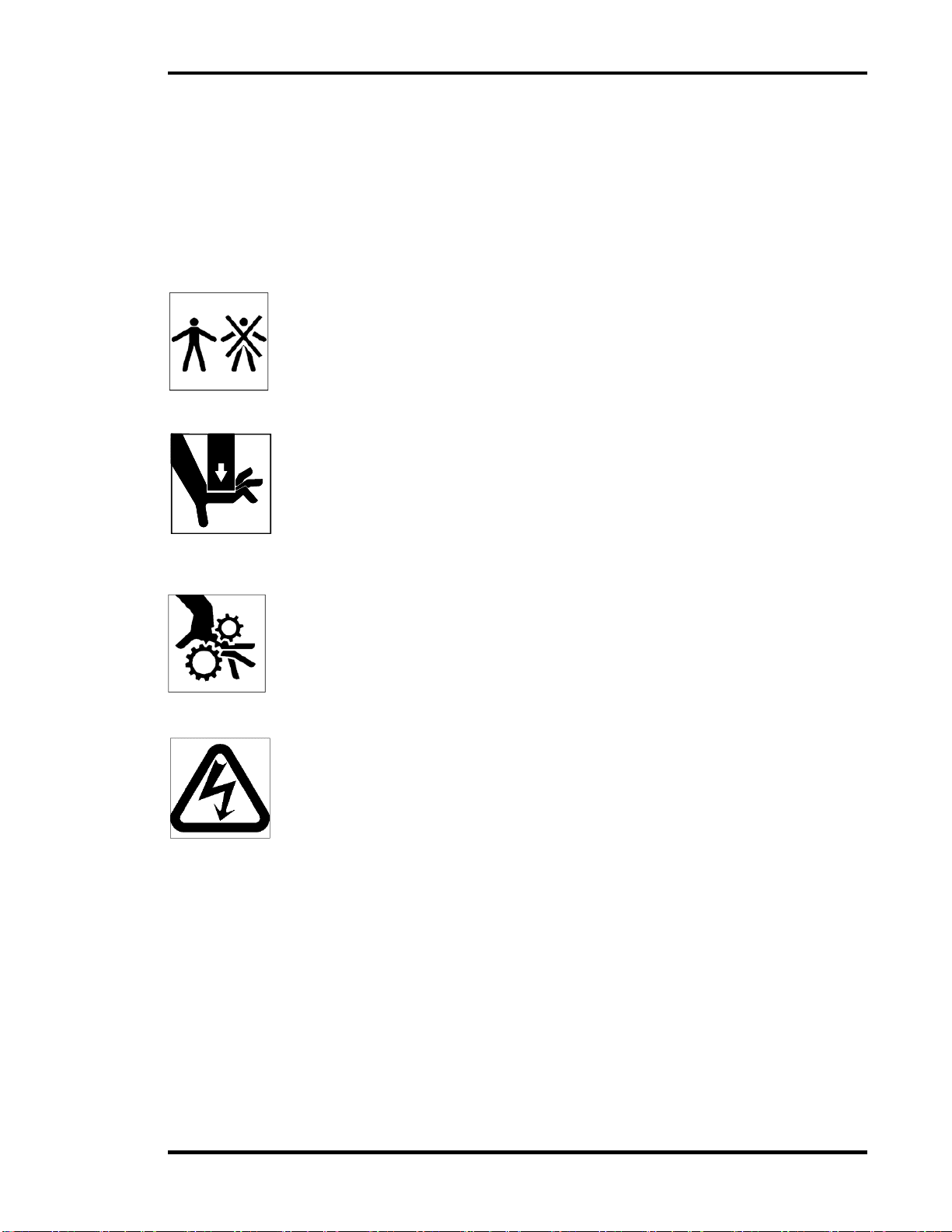
2.3 Warning Label Definitions.............................................................................................................5
3.0 Packing List...................................................................................................................................... 6
4.0 Specifications................................................................................................................................... 7
5.0 Accessories...................................................................................................................................... 8
6.0 Installation Guide ............................................................................................................................. 9
6.1 Inspecting Shipment.....................................................................................................................9
6.2 Unpacking.....................................................................................................................................9
6.3 Leveling.........................................................................................................................................9
6.4 Cleaning........................................................................................................................................9
6.5 Power Hook-up (SCM Models Only) ............................................................................................9
6.6 Knife and Die Installation..............................................................................................................9
7.0 User’s Guide .................................................................................................................................. 10
7.1 SCM/MSCM Diagrams .............................................................................................................. 10
7.2 SCM (Power Model) Operation ................................................................................................. 12
7.3 MSCM (Manual Model) Operation............................................................................................. 12
7.4 Side and Back Gauge Adjustment............................................................................................. 12
7.5 Knife and Die Change................................................................................................................ 12
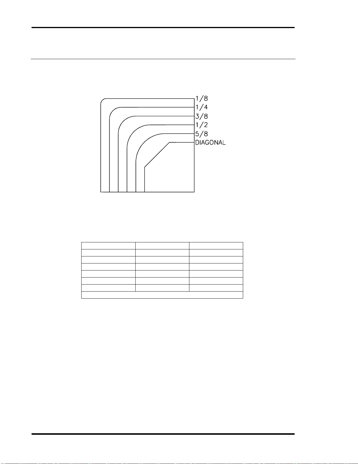
7.6 Straight Diagonal Cutting........................................................................................................... 15
7.7 Lubrication ................................................................................................................................. 16
7.8 Operating Tips ........................................................................................................................... 17
8.0 Appendix A - Maintenance Guide .................................................................................................. 18
8.1 Mechanical System.................................................................................................................... 19
8.1.1 Knife Return Springs .......................................................................................................... 19
8.1.2 Dovetail Gib........................................................................................................................ 20
8.2 Hydraulic System (SCM Models Only)...................................................................................... 21
8.2.1 Hydraulic Fluid Check ........................................................................................................ 21
8.2.2 Replacing Hydraulic Fluid................................................................................................... 22
8.2.3 Hydraulic Fluid Compatibility List ....................................................................................... 22
8.3 Electrical System (SCM Models Only)....................................................................................... 22
8.3.1 Circuit Breaker Check ........................................................................................................ 22
9.0 Appendix B–Parts List.................................................................................................................... 24
9.1 Mechanical................................................................................................................................. 24
9.1.1 A-8300-3 Main Assembly- Knife Head............................................................................. 24
9.1.2 A-8300-3 Main Assembly- Knife Head (Rear).................................................................. 26
9.1.3 A-8300-3 Main Assembly- Underside .............................................................................. 28
9.1.4 A-8300-3 Main Assembly- Hood ...................................................................................... 30
9.1.5 A-8300-3 Main Assembly- Base....................................................................................... 32
9.1.6 A-8300-3 Main Assembly- MSCM, S/N’s 142609M & Up ................................................ 36
9.1.7 83001-1 Hydraulic Power Unit Assembly- SCM, Rev. A.................................................. 38
9.2 Electrical .................................................................................................................................... 40
9.2.1 E-3356-1 Basic Machine Schematic ................................................................................. 40
9.2.2 E-3357-1 Interconnection Diagram ................................................................................... 41
9.2.3 EE-3358-1 Terminal Rail Assembly .................................................................................. 42
10.0 Appendix C- Troubleshooting ...................................................................................................... 44

2.0 Safety
4
2.0 Safety
2.1 Precautions
By nature of the functions the cornering machine performs, it has some inherent dangers
associated with its use. Read and thoroughly understand the safety precautions outlined below.
This machine is designed for one-person operation. Never operate the machine with more than
one person.
Cut/crush hazard. Keep hands from under the knife and clamp while in operation.
Do not operate with any covers removed.
After maintenance, all covers should be re-installed using the original hardware before resuming
normal operation.
Safe use of this machine is the responsibility of the operator. Use good judgment and common
sense when working with and around this machine.
Read and understand all instructions thoroughly before using the machine. If questions remain,
contact your Authorized Challenge Dealer. Failure to understand the operating instructions may
result in personal injury.
Only trained and authorized individuals should operate this machine.
Disconnect power before performing maintenance. See Section 2.2 , Power Lockout Procedure.
Observe all caution labels on this machine.
When replacing hydraulic parts, loosen the connections slowly to relieve pressure. Never loosen
connections while the machine is running. Allow hydraulic fluid to cool before performing
maintenance on the hydraulic system.
Never leave the machine unattended while running.
If the machine operates abnormally, consult Appendix C- Troubleshooting.
2.2 Power Lockout Procedure
For maximum safety while making adjustments or repairs to your machine, be sure to disconnect
power from the machine. Disconnect the power plug from its socket.
Figure 1 –Main Power Disconnect

2.0 Safety
5
2.3 Warning Label Definitions
The following warning label is found on the front cover of the machine. Read and understand the
meaning of this symbol. If this label is lost from the machine, it should be replaced.
SINGLE PERSON OPERATION
Do not operate with more than one person.
CUT/CRUSH HAZARD
Keep hands from under clamp and knife while in operation.
CRUSH HAZARD
Do not operate with any covers removed.
SHOCK HAZARD
Disconnect power before removing cover. Replace covers before operation.

3.0 Packing List
6
3.0 Packing List
SCM MSCM
(Single Cornering Machine) (Manual Single Cornering Machine)
Part No.
Description
Qty.
CMC-431B
Single Cornering Machine (SCM)
1
or
CMC-431M
Manual Single Cornering Machine (MSCM)
1
Each machine includes the following tool kit items.
83027
Hitch Pin
1
or 8315-1
Knife Hold-Down Block
-
S-1244-2
Lock Pin
1
W-171
1/8” hex wrench- long arm
1
W-172
3/16” hex T-wrench (extra long)
1
83014
Jogging Aid
1
W-130
3/16” hex wrench
1
6629
Gib Lube
1
W-105
1/4” hex wrench
1
W-131
5/16 hex wrench
1
83028
Knife Change Block (MSCM models only)
1

4.0 Specifications
7
4.0 Specifications
Description
US Units
Metric Units
Maximum Pile Height –SCM Models
4”
102 mm
Maximum Pile Height –MSCM Models
2”
51 mm
Table Depth
24”
610 mm
Table Width
20”
508 mm
Table Height
35”
889 mm
Overall Height
51”
1295 mm
Footprint
20 X 24”
1295 X 610 mm
Net Weight (SCM)
190 lb.
87 kg
Shipping Weight (SCM)
265 lb.
121 kg
Net Weight (MSCM)
145 lb.
66 kg
Shipping Weight (MSCM)
220 lb.
100 kg
Electrical (SCM Models Only)
120 V / 13.5 A / 1 phase, 60 Hz
½ HP
0.37 kW
20 A service size
230 V / 8 A / 1 phase, 50/60 Hz
15 A service size

5.0 Accessories
8
5.0 Accessories
Figure 2 Knives and Dies
Size
Knife Number
Die Number
1/8” / 3.2 mm
6721-2
6722-2
1/4" / 6.3 mm
6721-4
6722-4
3/8” / 9.5 mm
6721-6
6722-6
1/2" / 12.7 mm
6721-8
6722-8
5/8” / 15.9 mm
6721-10
6722-10
Straight Diagonal
6761
6762
1-1/4 / 32 mm maximum Straight Diagonal cut

6.0 Installation Guide
9
6.0 Installation Guide
6.1 Inspecting Shipment
The cornering machine has been carefully packed to prevent damage during shipment. However,
claims for damage or loss are the responsibility of the recipient. Inspect all shipments as soon as
they are received. If there is any noticeable damage, note it on the freight bill. Visual and/or hidden
damage must be reported to the claims department of the carrier within 15 days. Contact your dealer
if you need any assistance. Check the contents of the crate against the packing list on page 6. Make
sure there are no missing items.
6.2 Unpacking
Remove the packing materials and braces. Use a safe material handling device to lift the machine off
the skid. Secure the machine to any lifting or moving device using lifting straps. The machine weighs
over 250 lbs. (113 kg). If no lifting or moving devices are used, use at least two people to move the
machine. The machine should be lifted by gripping the edges of the table. Do not push or pull the
machine. A tip hazard may result! Note that the installation location must have a 120 VAC wall
outlet nearby.
6.3 Leveling
Once positioned, level the machine to the floor by turning one or more of the four levelers to the floor.
Turning a leveler clockwise moves it to the floor.
Figure 3 - Leveling
6.4 Cleaning
It may be necessary to clean the machine after installation. It may be cleaned with a solution of dish
soap and water. Do not use petroleum or acid based solvents to clean the machine. Damage may
result.
6.5 Power Hook-up (SCM Models Only)
Insert the power plug into nearby wall outlet. The machine should operate on a 20 Amp circuit. If the
pump motor stalls or operates sluggishly, test the line voltage. To many machines on one circuit will
reduce the voltage to each, affecting their performance.
6.6 Knife and Die Installation
See Section 7.5 Knife and Die Change on page 12.

7.0 User’s Guide
10
7.0 User’s Guide
7.1 SCM/MSCM Diagrams
Figure 4 - SCM (Power Model) Components

7.0 User’s Guide
11
Figure 5 - MSCM (Manual Model) Components

7.0 User’s Guide
12
7.2 SCM (Power Model) Operation
1. Switch on the main power. The main power switch is located on the left side of the stand,
underneath the table.
2. Lift the top cover guard and load the stock using the jogging aid. Jog the stock against the side
gauge to line it up. Push and jog it against the back gauge.
Keep hands away from the knife and plunger!
Always use the jogging aid while cutting.
3. Depress and hold the foot switch to cut. Release the foot switch after the knife stops moving
down. The knife returns to the up position. The hydraulic motor will shut off.
7.3 MSCM (Manual Model) Operation
1. Load the stock using the jogging aid. Jog the stock against the side gauge to line it up. Push and
jog it against the back gauge.
Keep hands away from the knife and plunger!
Always use the jogging aid while cutting.
2. Depress the foot pedal to cut. Let up on the foot pedal after the cut is complete.
7.4 Side and Back Gauge Adjustment
1. Switch off the machine and disconnect power. See Power Lockout Procedure on page 4.
2. Open the top cover.
3. Loosen the side gauge mounting screws and use a straight edge to align it tangent to the radius
on the die. Tighten the mounting screws.
4. Loosen the back gauge mounting screws. Place a square against the side gauge.
5. Adjust the back gauge square to the side gauge and tangent to the radius on the die. Tighten the
mounting screws.
6. Reconnect power to the machine
7.5 Knife and Die Change
Sharp knives! Even used knives are extremely sharp. Severe
lacerations may result from improper handling of knives.
1. Open the top cover.
(steps 2 –7 are for MSCM models ONLY):
2. Place the solid plastic square block under the clamp plunger.
3. Press down and hold the foot pedal.
4. Insert the knife change lock pin into the first (higher) hole in pressure foot guide shaft (Figure 6)
and release the foot pedal.
5. Place the jogging aid under the clamp plunger as shown in Figure 6.
6. Press down and hold the foot pedal.
7. Remove the knife change lock pin from the highest hole and insert it into the lower hole (Figure
6), then release the foot pedal.
(steps 8 –10 are for SCM models ONLY):
8. Place the jogging aid under the clamp plunger as shown in Figure 6.
9. Switch on power and press down and hold the foot switch.
10. Insert the knife change lock pin into lower hole in pressure foot guide shaft (Figure 6) and release
the foot switch.

7.0 User’s Guide
13
Figure 6 –Block Up the Clamp Plunger
11. Back off the knife adjustment setscrew to prevent damage to the new knife.
Figure 7 –Back Off the Setscrew
12. Remove the die mounting screws and die.
13. Remove the knife mounting screws and knife.
14. Place the new die on its mounting surface on the table and reinstall its mounting screws with the
pushed as far as possible toward the operator. Do not tighten.
15. Insert the new knife against the adjustment setscrew and install the knife mounting screw. Snug
the screw but do not tighten.
16. Remove the chip drawer.
17. Switch on the machine and place a piece of paper over the table sensor (SCM models only).
18. Depress the foot switch/foot pedal and hold it down.
19. Block the entire cutting head down using the block or hitch pin as shown in Figure 8.
Jogging Aid
Knife change
lock pin
Wrench for setscrew

7.0 User’s Guide
14
Figure 8 –Lock the Cutting Head Down
20. Release the foot switch/foot pedal.
21. Switch off the machine (SCM models only).
22. Place a piece of tissue paper between the knife and the die to ensure proper clearance as shown
in Figure 9.
Figure 9 –Tissue Paper between Knife and Die
23. Using the knife adjustment setscrew, adjust the knife until the cutting edge is 1/8” above the
surface on which the die mounts.
24. Securely tighten the knife mounting screw.
25. Adjust the die such that the radius of the die makes perfect contact with the radius of the knife.
Notice: As of November 2011, all Challenge dies have been redesigned to improve trimming of
the bottom sheets. You may notice differences between new dies and old style dies. Install new
dies as the old style dies were installed, but note the following differences:
The radius area of the die will fit more tightly into the radius area of the knife.
Wood Block
Hitch Pin

7.0 User’s Guide
15
There will be a more noticeable gap between the area of the knife and die that runs straight
after the radius.
Correct installation will look like the following diagram.
Figure 10 –Knife and Die alignment
26. Securely tighten the die mounting screws.
27. Remove all tools from the table. Close the top cover and reconnect power to the machine.
28. Switch on the machine (SCM models only).
29. Depress and hold down the foot switch/foot pedal. Carefully remove the hitch pin or hold-down
block.
30. Release the foot switch/foot pedal.
31. Remove the knife change lock pin by following steps 2 through 10 in reverse order.
32. Reinstall the chip drawer.
7.6 Straight Diagonal Cutting
Adjusting the side gauge will change the length of a straight diagonal cut. This length should not
exceed 1” when cutting 4” thick piles. It is possible to cut piles 2” thick and below at 1-1/4” length of
diagonal. See section 7.4 Side and Back Gauge Adjustment for side gauge adjustment instructions.
Figure 11 - Maximum Recommended Cut

7.0 User’s Guide
16
7.7 Lubrication
Proper lubrication is critical to prevent excessive wear to the machine.
Disconnect main power.
See Section 2.2 Power Lockout Procedure.
Use gib lube to lubricate the gib and both sides of the dovetail.
Use light machine oil to knife return rod and springs. Wipe off excess oil.
Figure 12 - Lubrication Locations
Use light machine oil to lubricate the rear pillow blocks, the foot pedal pull-down pin, and the
pull-down shoulder screw on the (MSCM models only).
Figure 13 - Pillow Blocks
Gib Lube Weekly
Light Machine Oil Weekly

7.0 User’s Guide
17
Figure 14 - Pin and Shoulder Screw
7.8 Operating Tips
Keep the knife and die sharp and in good alignment. A dull knife and poor adjustments lead
to irregular cuts. New or re-sharpened dies should be purchased through an authorized
Challenge dealer in order to insure proper sharpening.
Exercise care when handling and changing knives.
Firm placement of paper against side and back gauges will ensure good cuts.
Unusual noise and irregular operation indicates a maintenance check is due. A qualified
service technician should check the machine.
Follow the routine maintenance procedures. Keep chips off bearings and sliding parts.
Lubricate frequently with the Gib Lube provided in the toolkit. Always disconnect power
before lubricating. See Power Lockout Procedure on page 4.

8.0 Appendix A - Maintenance Guide
18
8.0 Appendix A - Maintenance Guide
NOTICE
The instructions on the following
pages are for the use of trained
service personnel only!
Attempting to perform repair and
replacement procedures without
proper training may cause
machine damage or operator
injury!
PARTS CUSTOMERS: The Challenge Machinery Company provides parts with the express
understanding that they are to replace parts found missing or no longer serviceable on
equipment designed and/or manufactured at Challenge. The Challenge Machinery
Company assumes no liability for any modification or alteration to any Challenge products,
and any such modification or alteration to any Challenge product is not authorized by The
Challenge Machinery Company. Any modification or alteration of any Challenge product
will void any remaining warranty.

8.0 Appendix A - Maintenance Guide
19
8.1 Mechanical System
8.1.1 Knife Return Springs
It may be necessary to adjust the knife return spring(s) at some time. More compression increases
the return force while less compression reduces the return force. The length of the spring should be
adjusted between 13-3/4 and 14 inches. Do not compress the spring(s) more than necessary. Over-
compression will cause undo wear to the spring(s). The following procedure describes how to adjust
the spring compression.
Disconnect main power.
See Section 2.2 Power Lockout Procedure.
1. Switch off the machine and disconnect power (SCM models only).
2. Open the top cover.
3. Loosen the top jam nut on the end of the knife return rod.
4. Turn the lower jam nut clockwise to increase the compression on the spring(s).
5. Turn the lower jam nut counter-clockwise to decrease the compression on the spring(s).
Figure 15 –Spring Compression Adjustment
6. Retighten the top jam nut onto the lower jam nut to lock it in place.
7. Close the top cover.
8. Reconnect power to the machine (SCM models only).

8.0 Appendix A - Maintenance Guide
20
8.1.2 Dovetail Gib
The dovetail gib may require adjustment occasionally. The following procedure describes how to
adjust the dovetail gib.
Figure 16 - Gib Adjustment
1. Remove the chip drawer.
2. Switch on the machine. Use scrap to cover the paper sensor in the table. Depress and hold the
foot switch/foot pedal.
3. Insert the knife hold-down block or hitch pin as shown in Figure 17.
Figure 17 –Lock the Cutting Head Down
Disconnect main power.
See Section 2.2 Power Lockout Procedure.
4. Switch off the machine and disconnect power (SCM models only).
5. Open the top cover.
6. Loosen three, gib-screw jam nuts and gib screws.
7. Place a .002” feeler gauge between the dovetail and the gib at the lower end of the gib.
8. Adjust the lower gib adjustment screw until the lower end of the gib contacts the feeler gauge.
Lock its jam nut in place and remove the feeler gauge.
Wood Block
Hitch Pin
Other manuals for SCM
1
This manual suits for next models
1
Table of contents
Other Challenge Industrial Equipment manuals
Popular Industrial Equipment manuals by other brands

GPS
GPS iMEASURE-D Installation, operation & maintenance manual

THORLABS
THORLABS KT120 user guide

Otto
Otto 750 Operation and maintenance manual

PI
PI L-412.XX9232 Series user manual

PCB Piezotronics
PCB Piezotronics HT356A24/NC Installation and operating manual

Schmalz
Schmalz 10.01.38.06443 Assembly instructions