manuals.online logo
Brands
  1. Home
  2. •
  3. Brands
  4. •
  5. Daikin
  6. •
  7. Industrial Equipment
  8. •
  9. Daikin DRC User manual

Daikin DRC User manual

Other manuals for DRC

2

This manual suits for next models

5

Other Daikin Industrial Equipment manuals

Daikin ESRH02A6 User manual

Daikin

Daikin ESRH02A6 User manual

Daikin NetPro Dual User manual

Daikin

Daikin NetPro Dual User manual

Daikin ECONMQ12P-8-1K User manual

Daikin

Daikin ECONMQ12P-8-1K User manual

Daikin VAM150HVE User manual

Daikin

Daikin VAM150HVE User manual

Daikin EWWD 340 User manual

Daikin

Daikin EWWD 340 User manual

Daikin VAM250FC User manual

Daikin

Daikin VAM250FC User manual

Daikin Clima-Flex CLIC Series Use and maintenance manual

Daikin

Daikin Clima-Flex CLIC Series Use and maintenance manual

Daikin SUT10D80L21-10-F User manual

Daikin

Daikin SUT10D80L21-10-F User manual

Daikin VAM350FC User manual

Daikin

Daikin VAM350FC User manual

Daikin VKM50GAMV1 User manual

Daikin

Daikin VKM50GAMV1 User manual

Daikin VAM250FC User manual

Daikin

Daikin VAM250FC User manual

Daikin ECORCH 40 Series User manual

Daikin

Daikin ECORCH 40 Series User manual

Daikin ECORICH EHU 40 Series User manual

Daikin

Daikin ECORICH EHU 40 Series User manual

Daikin EHU Series User manual

Daikin

Daikin EHU Series User manual

Daikin AllWorld Eco-Rich UEHU25-M07-15-30-V User manual

Daikin

Daikin AllWorld Eco-Rich UEHU25-M07-15-30-V User manual

Daikin LRYEN10A7Y1 User manual

Daikin

Daikin LRYEN10A7Y1 User manual

Daikin ECORICH R 40 Series User manual

Daikin

Daikin ECORICH R 40 Series User manual

Daikin LREN8A7Y1B User manual

Daikin

Daikin LREN8A7Y1B User manual

Daikin ERPV02A6 User manual

Daikin

Daikin ERPV02A6 User manual

Popular Industrial Equipment manuals by other brands

ABB +Q957 user manual

ABB

ABB +Q957 user manual

G.B.C BASIC EDGE 50 instruction manual

G.B.C

G.B.C BASIC EDGE 50 instruction manual

Tronair Batpak 11-6602-1000 Operation & service manual

Tronair

Tronair Batpak 11-6602-1000 Operation & service manual

Pilz PNOZ mi2p Operation manual

Pilz

Pilz PNOZ mi2p Operation manual

Clemco Zero BNP 6012 manual

Clemco

Clemco Zero BNP 6012 manual

Erskine Attachments V-Plow Operator's manual

Erskine Attachments

Erskine Attachments V-Plow Operator's manual

ABB HT610965 Operation manual

ABB

ABB HT610965 Operation manual

Morra MH 540 user manual

Morra

Morra MH 540 user manual

Eaton S090ST manual

Eaton

Eaton S090ST manual

GRIGGIO G 240 P4 instructions

GRIGGIO

GRIGGIO G 240 P4 instructions

Nexen AIR CHAMP HT45 user manual

Nexen

Nexen AIR CHAMP HT45 user manual

WTE V5 installation manual

WTE

WTE V5 installation manual

ABB HT845232 Operation manual

ABB

ABB HT845232 Operation manual

SMC Networks CJP Series Operation manual

SMC Networks

SMC Networks CJP Series Operation manual

JohnDow Industries JDI-AFT58 Operator's manual

JohnDow Industries

JohnDow Industries JDI-AFT58 Operator's manual

IMB MB9016A instruction manual

IMB

IMB MB9016A instruction manual

Clarke CUMB1 Assembly & operating instructions

Clarke

Clarke CUMB1 Assembly & operating instructions

amiad Arkal Spin Klin 2 user guide

amiad

amiad Arkal Spin Klin 2 user guide

manuals.online logo
manuals.online logoBrands
  • About & Mission
  • Contact us
  • Privacy Policy
  • Terms and Conditions

Copyright 2025 Manuals.Online. All Rights Reserved.

Safety Considerations
The following symbols and labels are used throughout this
manual to indicate immediate or potential safety hazards. It is
the owner’s and installer’s responsibility to read and comply
with all safety information and instructions accompanying these
symbols. Failure to heed safety information increases the risk of
personal injury, property damage, and/or product damage.
WARNING

      
       

       
        



      
  
        



WARNING


     
 



As a professional installer, you have an obligation to know
the product better than the customer. This includes all safety
precautions and related items.
Prior to actual installation, thoroughly familiarize yourself
with this Instruction Manual. Pay special attention to all safety
warnings. Often during installation or repair, it is possible to
place yourself in a position which is more hazardous than
when the unit is in operation.
Remember, it is your responsibility to install the product
safely and to know it well enough to be able to instruct a
customer in its safe use.
Safety is a matter of common sense...a matter of thinking
before acting. Most dealers have a list of specic good
safety practices...follow them.
The precautions listed in this Installation Manual are intended
as supplemental to existing practices. However, if there is a
direct conict between existing practices and the content of
this manual, the precautions listed here take precedence.

The 3-phase monitor kit for Light Commercial Models
veries the phase balance and, if out of balance, shuts the
unit down. “Out of balance” refers to the phasing being out
of sequence or loss of line voltage leg.
Ensure all parts are included before beginning. If parts are
missing from the kit, contact the distributor where the kit was
purchased.
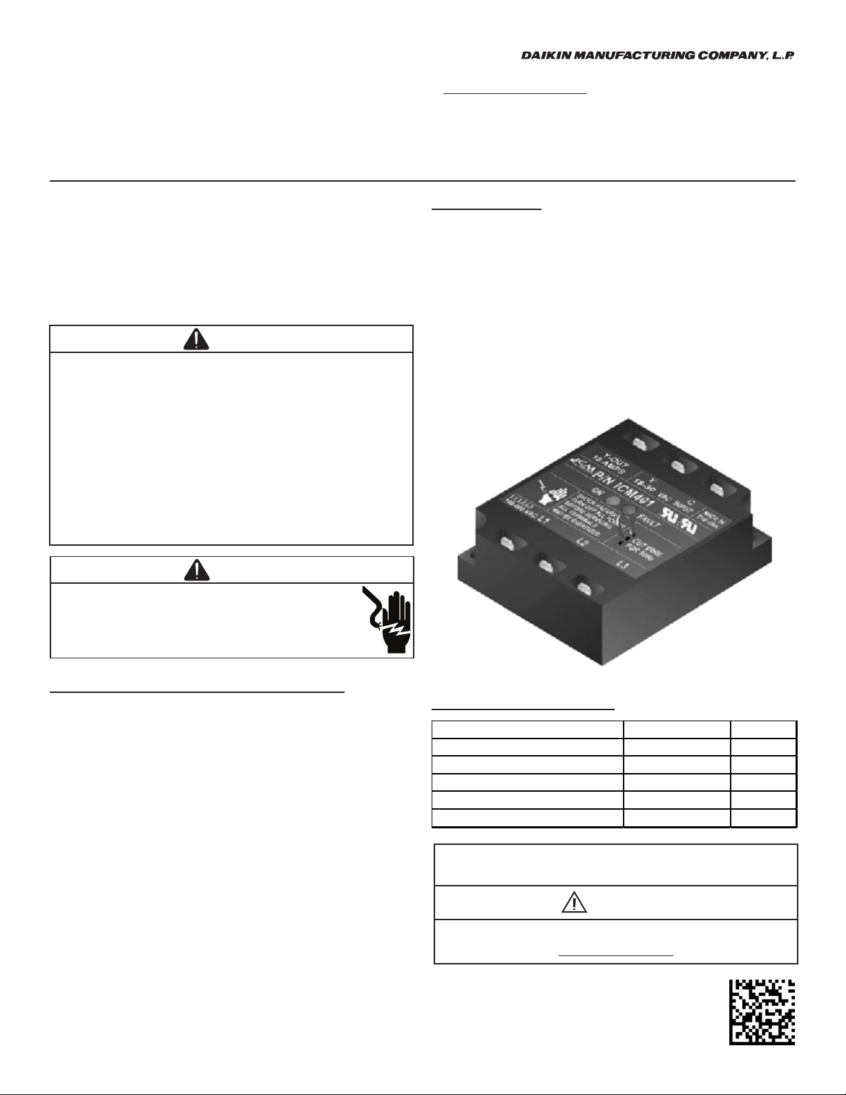
An illuminated green LED indicates the output is energized
and an illuminated red LED indicates there is a fault where
the Y-out terminal will be disconnected from the Y. If neither
is illuminated then the 24V power is o󰀨. An image of the
monitor is shown in Figure 1.
Figure 1

  QTY
Phase Monitor 0130L00105 1
Power Harness (3-6 Ton) 0259L00513 1
Low Voltage Harness (3-6 Ton) 0259L00517 1
Screws M0218153 2
Wire Ties M0321204 10




© 2019-2020
19001 Kermier Rd., Waller, TX 77484


WARNING
PROP 65 WARNING
FOR CALIFORNIA CONSUMERS
Cancer and Reproduive Harm -
www.P65Warnings.ca.gov 0140M00517-A
2

WARNING


     
 



1. Disconnect all power to the unit.
2. Remove access panel to control box.

1. Refer to Figure 3 for the approximate placement of the
phase monitor in the control box.
2. Using the screws provided in the kit, secure the phase
monitor to the control box.
3. Connect the Power Harness (Refer to Figure 2).
a.
The insulated straight quick connects go to the
phase monitor.
b. Connect Black to L1.
c. Connect Red to L2.
d. Connect Orange to L3.
e. Connect the opposite end of the harness to the
corresponding L1, L2, and L3 terminals on the power
block.
       
    



Wiring is subject to change. Always refer to the unit wiring diagram and accessory wiring diagram booklet for the most up-to-date wiring.
3

1. Connect the Low Voltage Harness (Refer to Figure 2).
a.
The insulated straight quick connects go to the
phase monitor.
b. Connect Purple wire to Y-OUT.
c. Connect Red wire to Y.
d. Connect Blue wire to C.
e. Unplug the 4 pin safety jumper male plug from the 4
pin safety female plug on the unit.
f. Connect new 4 pin phase monitor male plug
into the
4 pin safety female plug o
n the unit.
g.
Connect the 4 pin safety male jumper plug to the 4 pin
phase monitor female plug of the phase monitor.
Figure 3

4

  QTY
Phase Monitor 0130L00105 1
Power Harness (7.5-12.5 Ton) 0259L00514 1
Low Voltage Harness (7.5-12.5 Ton) 0259L00518 1
Screws M0218153 2
Wire Ties M0321204 10

WARNING


     
 



1. Disconnect all power to the unit.
2. Remove access panel to control box.

1. Refer to Figure 4 for the approximate placement of the
phase monitor in the control box.
2. Using the screws provided in the kit, secure the phase
monitor to the control box.
3. Connect the Power Harness (Refer to Figure 2).
a.
The insulated straight quick connects go to the
phase monitor.
b. Connect Black to L1.
c. Connect Red to L2.
d. Connect Orange to L3.
e. Connect the opposite end of the harness to the
corresponding L1, L2, and L3 terminals on the power
block.
5

1. Connect the Low Voltage Harness (Refer to Figure 2).
a.
The insulated straight quick connects go to the
phase monitor.
b. Connect Purple wire to Y-OUT.
c. Connect Red wire to Y.
d. Connect Blue wire to C.
e. Unplug the 4 pin safety jumper male plug from the 4
pin safety female plug on the unit.
f. Connect new 4 pin phase monitor male plug
into the
4 pin safety female plug o
n the unit.
g.
Connect the 4 pin safety male jumper plug to the 4 pin
phase monitor female plug of the phase monitor.
Figure 4

6
THIS PAGE INTENTIONALLY LEFT BLANK
7
THIS PAGE INTENTIONALLY LEFT BLANK
CUSTOMER FEEDBACK
Daikin is very intereed in all produ comments.
Please ll out the feedba form on the following link:
https://daikincomfort.com/conta-us
You can also scan the QR code on the right to be direed to the feedba page.
8
Our continuing commitment to quality products may mean a change in specications without notice.
© 2019-2020
19001 Kermier Rd., Waller, TX 77484
www.daikincomfort.com