cinetics AXIS360 User manual

Quick Start Guide
Basic set-up for your
Axis360 system

Table of Contents
1| Setting up Slide
slider assembly
attach belt to cart
attach ballhead to cart
connect motor to controller
attach slider to tripod(s)
2| Setting up Pan
option #1 for tripod mount
option #2 for slider mount
3| Setting up Tilt
4| Setting up Pan and Tilt
5| Setting up Slide and Pan
6| Setting up Slide, Pan, and Tilt
7| Quickstart Controller Settings
1.
3
3
4
6
6
7
8
8
9
11
13
14
15
16

Parts
2.
Optional: Shutter Release Cable
3
3
4
6
6
7
8
8
9
11
13
14
15
16

1 | Setup up Slide
Step 2. Remove end caps from rails (Figure 1)
Step 3. Remove outrigger leg from rails (Figure 2)
Step 4. Attach additional rails, screw together all the way
Step 5. Move rail brace to the center where the rails connect (Figure 3)
Step 6. Replace outrigger leg and end caps
Slider Assembly (The slider comes partially assembled)
Step 1. First take your slider and un-fold the outrigger legs by loosening the knobs. Position the legs so
your slider is standing. For ideal balance, you don’t want legs too narrow or too spread apart
Be sure to push outrigger legs all the way on, this is important for putting on the belt
3.
See it in video here: https://vimeo.com/90878151
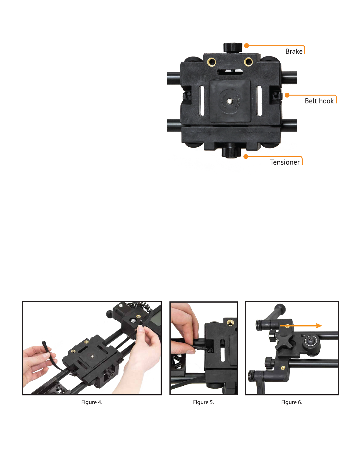
The side with the raised Cinetics lettering
is the brake, tighten or loosen to engage or
disengage brake. The other side is the
tensioner, tighten to make sure it is tight
enough to keep the weight of the camera
level on the rails without tightening too
much to restrict the slide.
1 | Setup up Slide cont.
Cart Overview
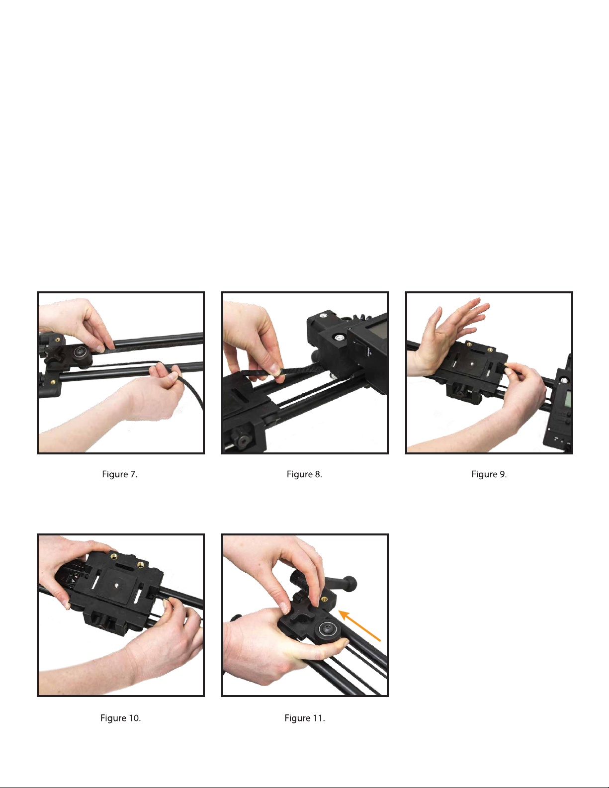
Attach the motor drive belt
TIP: It is important that the belt is taut and without any slack
Step 7. Take one end of the belt and loop it under the cart so you won’t have to thread it through later
(Figure 4)
Step 8. Push the belt loop down with your finger and lock into the cart hook. You want the grooved side
of the belt facing inward. Pull tight so there is no extra room around the hook (Figure 5)
Step 9. Put on brake to stop your cart from moving
Step 10. Loosen pulley tensioner and bring all the way forward (Figure 6)
4.
See it in video here: https://vimeo.com/121074865
Attach the motor drive belt cont.
Step 11. Loop the belt around the pulley with the grooved side inward for grip (Figure 7)
Step 12. Thread belt under the cart and loop belt around the motor on the other end of the slider (Figure 8)
Step 13. Release brake on the cart by loosening the brake
TIP: To attach the other belt loop you can use your hand to push the cart toward the belt loop you are
hooking on, this will reduce any slack in the belt (Figure 9)
Step 14. Push the other belt loop down over the hook (Figure 10)
Step 15. Tighen pulley tensioner by pushing it away from the cart, then secure it by tightening the knob;
The belt should be taut (Figure 11)
1 | Setup up Slide cont.
5.

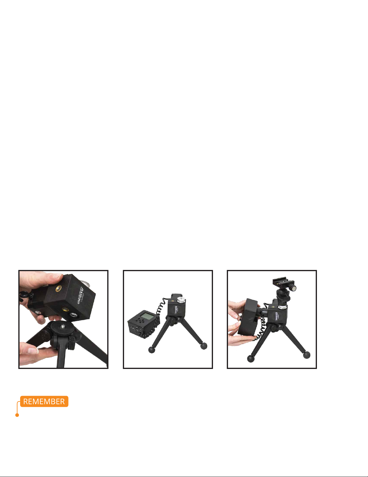
Attach Ballhead to Cart
Step 16. Attach ballhead, you can use the one we provide or your own (Figure 12)
Step 17. Under cart use the silver screw to secure ballhead to cart, tighten with Hex Key (Figure 13)
Step 18. Screw Clamp onto ballhead and arca-style plate into your camera
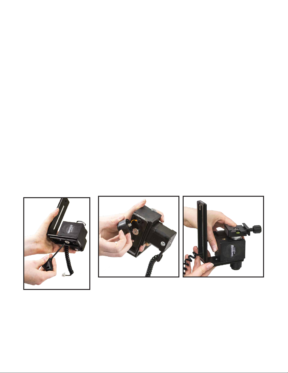
Connect Motor to Controller
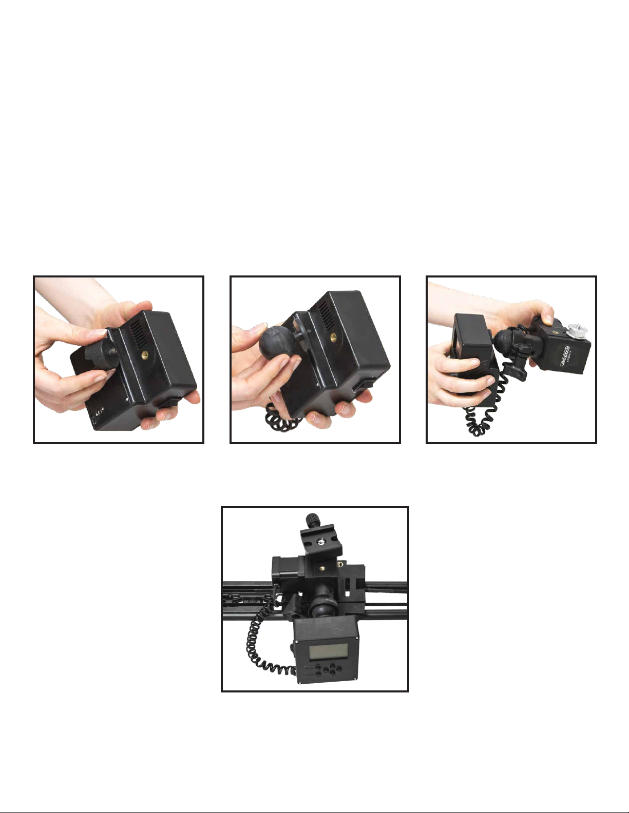
Step 19. Plug motor cable into Motor Port (Figure 14)
Step 20. Snap motor onto the Male Quick Connect piece next to the motor (Figure 15)
TIP: Snap the Quick Connect pieces together by first positioning them together at an angle then
pushing downward and forward like popping on a bottle cap (Figure 16)
Step 21. Place camera on ballhead
Step 22. Connect camera cable to camera
Figure 12.
1 | Setup up Slide cont.
Figure 13.
Figure 14.
Figure 15. Figure 16. 6.

1 | Setup up Slide cont.
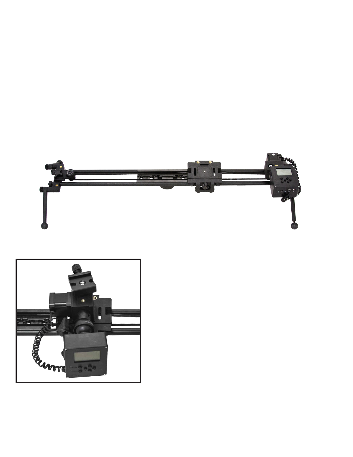
Attach Slider to Tripod(s)
You can mount the Axis360 on any tripod by connecting it to the rail brace or outrigger legs. The Rail
Brace has a 3/8"-16 thread and the Outrigger Legs have 1/4”- 20 threads. The Slider can be mounted
horizontally or vertically.
Figure 17. Figure 18.
Two Axis360 vertical slider setup on tripod
7.
Parts Needed:
Arca-style plate
Motor
Ballhead
Controller
Tripod
There are two preferred setup options:
Option 1. Attachment for Tripod
Step 1. Attach Axis360 Motor to tripod (Figure 19 & 20)
Step 2. Place ballhead on Axis360 Motor and attach the clamp to it (Figure 21)
Step 3. Attach arca style plate to camera and slide into clamp
TIP: Make sure clamp is securely tightened
Step 4. Connect cable to controller Camera Port (Figure 14)
Step 5. Snap the controller onto the motor using the quick connect pieces (Figure 15, 16 & 21)
2 | Setup up Pan
For heavier cameras we recommend a sturdy ballhead. You can attach a clamp directly onto the
motor (instead of the ballhead).
Figure 19. Figure 20. Figure 21.
8.
See it in video here: https://vimeo.com/101748664

Option 2. Attachment for Slider
This set up is preferred for mounting on the slider for a SLIDE AND PAN though it also works on a tripod.
Step 1. Separate ballhead from Male Quick Connect (Figure 22 & 23) and set aside
TIP: Make sure the ballhead grip is un-tightened. It’s easier to un-snap the piece when the ballhead is
connected to something such as a tripod
Step 2. Screw Threaded Male Quick Connect into Motor and snap ballhead onto that connector (Figure 24)
2 | Setup up Pan cont.
Connector
Piece
Figure 22. Figure 23.
Cinetics Quick Connect Pieces
Threaded Male Quick ConnectMale Quick Connect Female Quick Connect
Figure 24.
9.
See it in video here: https://vimeo.com/97264416
2 | Setup up Pan cont.
Option 2. Attachment for Slider cont.
Step 3. Remove Female Quick Connect from controller (Figure 25)
Step 4. Unscrew ballhead and remove ball. Screw ball into the back of the controller (Figure 26)
Step 5. Take controller, now with ballhead ball, and mount controller into ballhead clamp (Figure 27)
Step 6. Mount arca-style clamp onto motor thread and thread arca-style plate into your camera
Step 7. Connect motor cable to controller
Figure 25. Figure 26. Figure 27.
10.
Figure 36. Assembled Pan setup
Option #2 mounted on slider cart
Parts Needed:
Motor
L-Bracket (2)
Clamp (2)
Controller
Hex Key
Step 1. Mount motor on short side of L-Bracket, tighten with hex key (Figure 28)
Step 2. Screw Threaded Male Quick Connect into bottom of L-Bracket (Figure 29)
Step 3. Mount clamp to motor thread (Figure 30)
Step 4. Attach short side of 2nd L-Bracket to clamp and tighten (Figure 30)
Step 5. Snap controller into connector
Step 6. Connect motor cable to controller
3 | Setting up Tilt
Figure 28.
Figure 29. Figure 30.
11.
See it in video here: https://vimeo.com/97264416
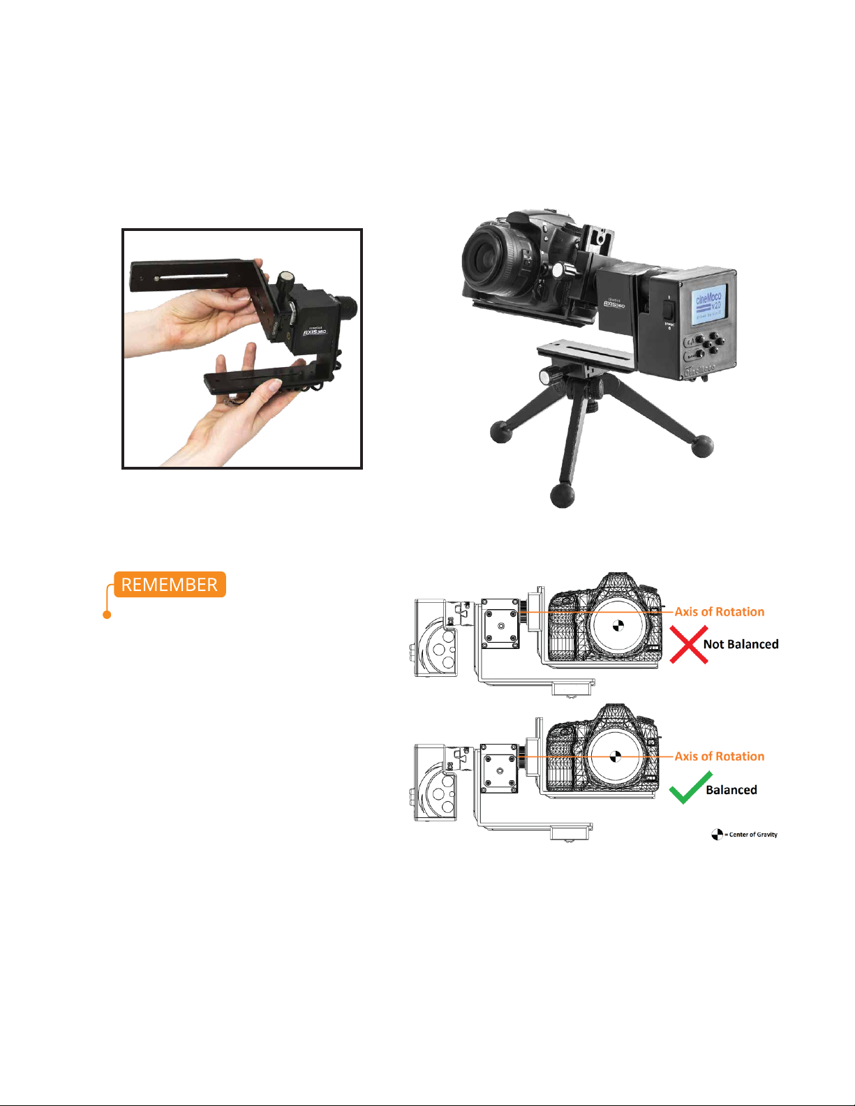
Figure 31.
Step 7. Put ballhead with clamp on tripod. Slide the long end of the L-Bracket supporting the
controller into ballhead clamp and securly tighten clamp (Figure 32)
3 | Setting up Tilt cont.
12.
When panning or tilting,
balancing is a critical procedure
in making sure that Axis360
works correctly. Balancing simply
requires that the camera’s center
of gravity is located as close as
possible to the axis of rotation.
Position the L -bracket so that
the camer’s center of gravity is
located near the axis of rotation.
Figure 32.
Finding a camera’s center of gravity must be acquired empirically (the center of the lens may
not necessarily be the center of gravity

Parts Needed:
Assembled Pan Setup Option # 1 (Page 8)
Assembled Tilt setup (Page 11)
Sturdy Tripod
Step 1. Place Pan setup #1 on tripod, remove ballhead and attach clamp directly to motor (Figure 33)
Step 2. Take assembled Tilt Setup and slide the long end of the L-Bracket supporting the controller into
the motor clamp. Securly tighten clamp (Figure 34)
4 | Setting up Pan and Tilt (2 Axis System)
Figure 33. Figure 34.
13.
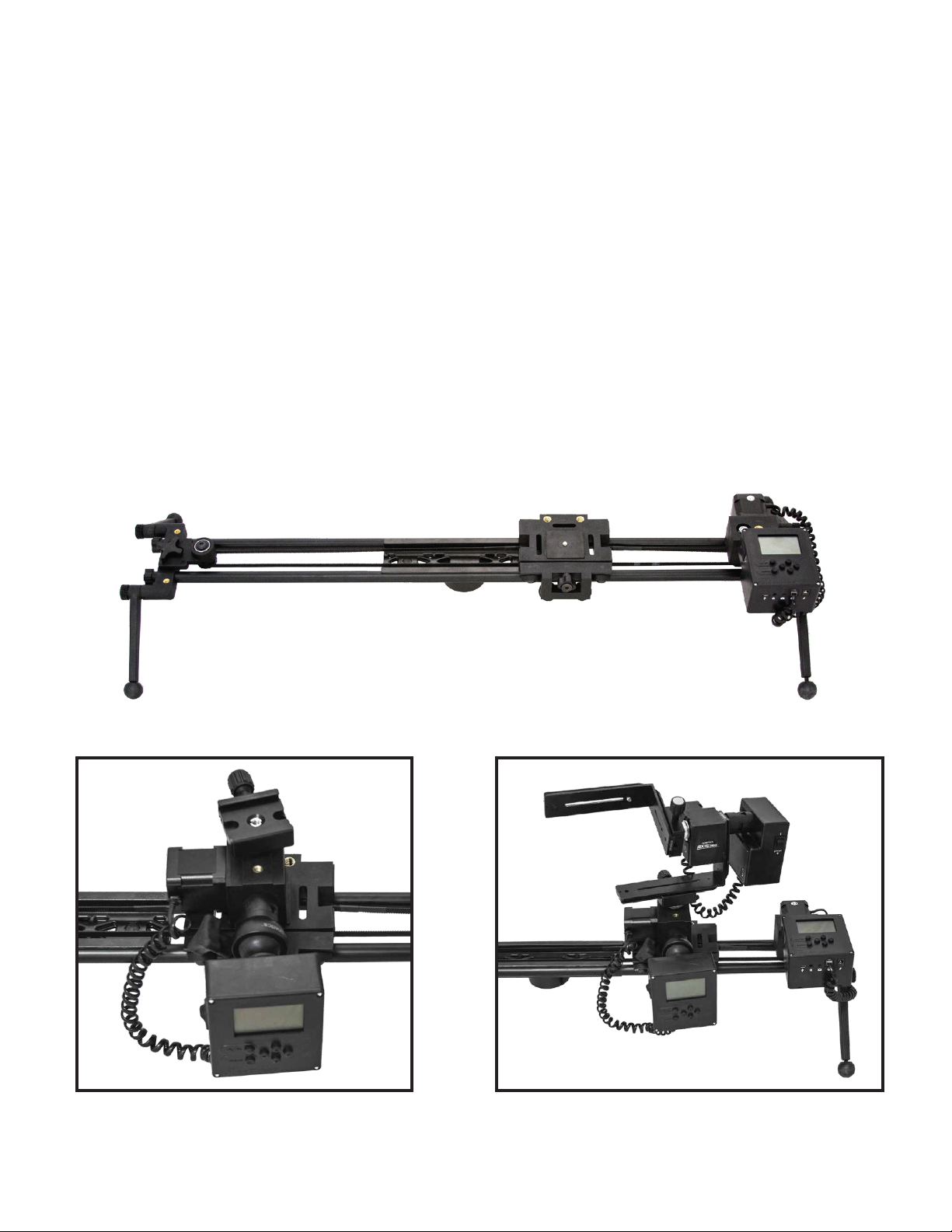
Parts Needed:
Assembled Slider setup (Page 3)
Assembled Pan setup Option #2 (Page 9)
Step 1. Assemble Slider setup (Figure 35)
Step 2. Assemble Pan setup #2 and place directly onto the cart, motor down (Figure 36)
Step 3. Screw in cart thread to bottom of Axis360 motor and tighten with Hex Key
5 | Slide and Pan (2 Axis System)
Figure 36. Assembled Pan setup
Option #2 mounted on slider cart
Figure 35. Assembled Slider setup
14.
See it in video here: https://vimeo.com/97264416
Parts Needed:
Assembled Slide setup (Page 3)
Assembled Pan setup Option #2 (Page 9)
Assembleed Tilt setup (Page 11)
Step 1. Assemble Slider setup (Figure 37)
Step 2. Place Pan setup #2 directly onto the cart, motor down (Figure 38)
Step 3. Screw in cart thread to bottom of Axis360 motor and tighten with Hex Key
Step 4. Take assembled Tilt Setup and slide the long end of the L-Bracket supporting the controller
into the motor clamp. Securly tighten clamp (Figure 39)
6 | Setting up Slide, Pan and Tilt (3 Axis System)
Figure 38. Assembled Pan setup
Option #2 mounted on slider cart
Figure 37. Assembled Slider setup
Figure 39.
15.
See it in video here: https://vimeo.com/97264416

1 AXIS PAN/TILT/SLIDE TIMELAPSE
We recommended that you first read the CineMoco Instructional Manual for a more detailed breakdown
of the controller menu functions.
Menu Page Settings:
There are four sections of the menu: GEN (General), CON (Controller), MTR (Motor), CAM (Camera).
To scroll through each section just press the Menu button
When shooting a timelapse, make sure your camera is set to Manual Mode. Auto Focus is not recommend
as it will usally take too long to focus between shots.
Step 1: Plug your camera cable into the controller and camera
Step 2: Press menu button so GEN is selected
Step 3: Use the arrow keys to move up and down in the menu
Step 4: Highlight over Record and use the right arrow key to change the mode to Timelapse
Step 5: Move down to Setup and use the right arrow key to change the setup to Keyframes
Step 6: Leave Scrl Ramp at default
Step 7: Press MENU to move over to the MTR menu tab
Step 8: Select your Motor Type (Slider for Slide, Pan/Tilt for Pan or Tilt)
OPTIONAL: Select Speed to change the Motor speed, choose from Low, Medium, or High
Step 9: Press MENU to move over to CAM menu tab
Step 10: Highlight over Cam Type and press the right arrow to select your camera type
Step 11: Highlight over Fire Test Shot and hit the right arrow to take a picture and make sure your
camera is connected
7 | Quickstart Controller Settings
Home/Play
Menu
Navagation
Arrows
Power Switch
16.
See it in video here: https://vimeo.com/127733270
Main Page Settings
Press the Home/Play button. This is where you can customize your timelapse settings
Step 1: First set your End Point
Step 2: Do the above to set your Start Point
You can select Go to Start or Go to End by pressing the right arrow. This will show you the positions you
set for your start and end. If needed, you can make any adjustments; just make sure you select either
Set Start Point or Set End Point again by hitting the right arrow key to confirm
Step 3: Scroll down to Record Time
Choose Record Time by pressing the right and left arrow keys to adjust the number
Step 4: Set Playback Time
Press the right and left arrow keys to adjust the number
Step 5: Choose Exposure
Press the right and left arrow keys to adjust the number
Step 6: Choose PlayB FPS (Playback Frames Per Second)
This will change the desired number of photos
Generally 24 FPS
Step 7: Choose Move Type
7 | Quickstart Controller Settings cont.
Moving the right or left arrow will spin the motor right and left
Find the place you want your timelapse to end
To set End Point scroll down to Set End Point with the down arrow
then hit the right arrow button
There will now be a check mark next to Set End Point
S-M-S (shoot-move-shoot) stops to take a photo, moves, stops to take
a photo, moves and so on..
Continuous never stops moving while shooting the photos
Exposure should always be faster than the interval time so that camera has time to shoot before the
next movement
17.

Main Page Settings cont.
When you are ready press the play button. On the screen you will see how many photos are going to be
shot, and as the Controller begins shooting, you will see how many photos it has shot so far. Pressing play
will end the timelapse.
General Settings:
Exposure: a good place to start is at 1.0s but you can change it to what you need depending on your
environment. This setting needs to be longer than your camera exposure setting so the camera does not
move while a photo is being fired during a S-M-S (shoot-move-shoot) mode. Setting your camera to Bulb
Mode enables this setting to control the camera’s exposure time, instead of just triggering it.
Record Time: 01:00:00s (for a 1 hour timelapse)
PlayB Time: 0:30s (desired video playback time).
Move Type: S-M-S (camera shoots, camera moves, camera shoots)
PlayB FPS: 24 fps
Ramp: Default 5%
7 | Quickstart Controller Settings cont.
18.
Table of contents
Popular Bicycle manuals by other brands


Fallowgate Limited
Fallowgate Limited BATRIBIKE user manual

Derby cycle
Derby cycle IMPULSE 2.0 SPEED owner's manual

Flyer
Flyer Gotour 6 Translation of the original instruction manual

Big cat
Big cat G H O S T R I D E R instruction manual

Motovox
Motovox MVX70 owner's manual

GLOBBER
GLOBBER EXPLORER TRIKE 4in1 DELUXE PLAY manual


