CIPU CSPPV711 User manual

READ AND FOLLOW ALL INSTRUCTIONS IN THIS OWNER’S
MANUAL AND ONEQUIPMENT.
This equipment must be installed and serviced by aqualified technician or professional,
in accordance with the National Electrical Code and all applicable local codes and
Ordinances. Improper installation can create electrical hazards which could result in
property damage, seriousinjury or death. Improper installation will void the warranty.
Notice to Installer
This manual contains important information about the installation,operation and safe
use of this product. Once the product has been installed this manual must be given to
the owner/ operator of this equipment.
Inground
VS Pumps
Item # CSPPV711

Water temperature in excess of 100°F(37.7°C) may be hazardous to your
health. Prolonged immersion in hot water may induce hyperthermia.
Hyperthermia occurs when the internal temperature of the body reaches a
level several degrees above normal body temperature of 98.6°F(37°C.).
Effects of hyperthermia include: (1) Unawareness of impending danger. (2)
Failure to perceive heat. (3) Failure torecognize the need to leave the spa. (4)
Physical inability to exit the spa. (5) Fetal damage in pregnant women. (6)
Unconsciousness resulting in danger of drowning. The use of alcohol, drugs,
or medication can greatly increase the risk of fatal hyperthermia in hot tubs
and spas.
To reduce the risk of injury, do not permit children to use or operate this
equipment.
When setting up pool water turnovers or flow rates, the operator must consider
local codes governing turnover as well as disinfectant feed ratios.
If this pump is intended for use in other than single-family dwellings, a clearly
labeled emergency switch shall be provided as part of the installation. The switch shall be
readily accessible tothe occupants and shall be installed at least 5 feet (1.52 m) away,
adjacent to and within sight of this pump.
RISK OF ELECTRICAL SHOCK OR ELECTROCUTION:
PUMPS REQUIRE HIGH VOLTAGE WHICH CAN SHOCK, BURN, OR
CAUSEDEATH. Before working on pump, always disconnect power tothe
pool pump at the circuit breaker before servicing the pump. Failure to do so
could result in death or serious injury to service person, pool users or others
due to electric shock.
Pumps improperly sized or installed or used in applications other than for
which the pump was intended can result in serious personal injury or death. These risks may
include but not be limited to electric shock, fire, flooding, suction entrapment or serious injury
or property damage caused by a structural failure of the pump or other system component.
Never exceed the maximum stated pump flow rating.Only use a pumping
system rated for the corresponding flow. FAILURE TO DO SO CAN RESULT INHAIR OR
BODY ENTRAPMENT WHICHCAN CAUSE SERIOUS PERSONAL INJURY OR DEATH. If in
doubt about the rating of your system, consult a qualified pool service professional.
Pumps are not a substitute for properly installed and secured pool drain covers.
An ANSI/ASME A112.19.8 approved anti-entrapment drain cover must be used for each drain.
Pools and spas should utilize a minimum of two drains per pump. Regularly inspect all covers
for cracks, damage and advanced weathering. If a cover becomes loose, cracked, damaged,
broken or is missing, closethe pool or spa immediately, shut off the pump, post a notice and
keep the pool or spa closed until an appropriate VGB 2008 certified cover is properly installed.
Covers deteriorate over time due to exposure to sunlight and pool chemicals. This cover must
be replaced within seven (7) years from installation (or earlier if the cover becomes damaged
in any way).
1

Hair Entanglement –When the hair tangles or knots in the drain cover, trapping the swimmer
underwater. This hazard is present when the flow rating of the cover is too small for the pump
or pumps.
Limb Entrapment –When a limb is sucked or inserted into an opening resulting in a
mechanical bind or swelling. This hazard is present when a drain cover is missing, broken,
loose, cracked or not properly secured.
Body Entrapment –When a portion of the body is held against the drain cover trapping the
swimmer underwater. This hazard is present when the drain cover is missing, broken or the
cover flow rating is not high enough for the pump or pumps.
Evisceration/Disembowelment –When a person sits on an open pool (particularly a child
wading pool) or spa outlet and suction is applied directly tothe intestines, causing severe
intestinal damage. This hazard is present when the drain cover is missing, loose, cracked, or
not properly secured.
Mechanical Entrapment –When jewelry, swimsuit, hair decorations, finger, toe or knuckle is
caught in an opening of an outlet or drain cover. This hazard is present when the drain cover is
missing, broken, loose, cracked, or not properly secured.
GENERAL SAFETY RULES
1. The products mentioned in this manual are specially designed for the pre-filtering and
re-circulation of water in swimming pools and spas.
2. They are designed towork with clean water at a temperature not exceeding 104 40!!
3. The installation should be carried out in accordance tothe safety instructions of swimming
pools, especially Standard HD 384.7.702 , and the specific instructions for each facility.
4. The compulsory rules on accident prevention should be carefully followed.
5. Any modification of the pump requires the prior consent of the manufacturer. Original
replacement parts and accessories authorized by the manufacturer ensure a high level of
safety. The manufacturer of the pump assumes no liability for the damage and injuries caused
by un-authorized replacement parts and accessories.
6. During operation, some parts of the pump are subject to dangerous electric voltage. Work
may only be performed on each pump or on the equipment connected to it after disconnecting
them from the main power and after disconnecting the starting device.
7. The user should make sure that assembly and maintenance tasks are carried out by
qualified authorized persons and that these persons have first carefullyread the instructions
for service and installation.
2
WARNINGS AND IMPORTANT SAFETY PRECAUTIONS
SUCTION ENTRAPMENT HAZARD

8. The operating safety of the pump is only guaranteed ifthe installation and service
instructions are correctly followed.
9. The limit values stated inthe technical table should not be exceeded under any condition.
10. Inthe event of defective operation or fault, contact the technical support department of the
manufacturer or it’s nearest authorized agents.
11. Ifthe supply cord is damaged, it must be replaced by the manufacturer or its service agent
or a similarly qualified person to avoid a hazard.
12. The pump must not be used when people are in the water.
13. The pump must be supplied through a residual current device (RCD) having a rated
residual operating current not exceeding 30mA.
14. Children should be under close supervision to prevent them from playing with the pump.
15. This appliance is not intended for use by persons (including children) with reduced physical,
sensory or mental capabilities, or lack of experience and knowledge, unless they have been
given supervision or instruction concerning use of the appliance by a person responsible for
their safety.
16. The pump must be protected from running dry.
Important Electrical Notice
The electrical installation isto be done by a licensed electrician.
Each pump requires a circuit breaker to separate the pump from the electrical supply.
The open contact distance of the circuit breaker is to be no less than 3mm
The pump is to be supplied by an isolating transformer, or supplied through a residual current
device (RCD) with a rated residual current not exceeding 30mA.
Checkthe pumps name plate for the following: Voltage, Amp draw and Cycle.
The power cord, including the ground wire shall have a quality of 245 IEC66 (HO7RN-F) for
models greater than 1kW power input.
For models less than 1kW input the quality shall be of 245 IEC57 (H05RN-F).
All installations must comply with local codes, based on IEC 364-7-702 requirements.
RESPECT THE MINIMUM GAUGE GIVEN IN THE CHART OF THE TECHNICAL MANUAL.
INSTALLATION
Location
Note: Do not install this pump within an outer enclosure or beneath the skirt of a hot tub or
spa unless marked accordingly.
Note: Ensure that the pump is mechanically secured tothe equipment pad.
Be sure the pump location meets the following requirements:
1. Install the pump as close tothe pool or spa as possible. To reduce friction loss and improve
efficiency, use short, direct suction piping returns.
2. Install a minimum of 5 feet (1.52 meters) from the inside wall of the pool and spa. Canadian
installations require a minimum of 9.8 feet (3 meters) from pool water level.
3. Install the pump a minimum of 3 feet (9 meters) from the heater outlet.
4. Do not install the pump more than 10 feet (3.1 meters)above the water level.
5. Install the pump inawell ventilated location protected from excessive moisture (i.e., rain
gutter downspouts, sprinklers, etc.)
3

6. Install the pump with a rear clearance of at least 3 inches (76.2mm) so that the motor can be
removed easily for maintenance and repair. See Figure 1.
Piping
1. For improved pool plumbing, it is recommended to use a larger pipe size. When installing
the inlet and outlet fittings (male adaptors), use thread sealant.
2. Piping on the suction side of the pump should be the same or larger than the return line
diameter.
3. Plumbing on the suction side of the pump should be as short as possible.
4. It is recommended that a valve, elbow or tee installed inthe suction line should be no closer
to the front of the pump than five (5) times the suction line pipe diameter. See Figure 2.
Example:
A 2 inch pipe requires a 10 inch (254 mm) straight run in front of the suction inlet of the pump.
This will help the pump prime faster and last longer
Fittings and Valves
1. Do not install 90°elbows directly into pump inlet.
2. Flooded suction systems should have gate valves installed on suction charge pipes for
maintenance, however, the suction gate valve should be no closer than five times the suction
pipe diameter as described in this section.
3. Use a check valve in the discharge line when using this ump for any application where there
is significant eight tothe plumbing after the pump.
4. Be sure to install check valves when plumbing in parallel with another pump. This helps
Figure 1:Pump Rear and Overhead Clearance
Figure 2 Recommended Piping
4
prevent reverse rotation of the impeller and motor.
Electrical Requirements
·Install all equipment in accordance with the National Electrical Code and all applicable local
codes and ordinances
·Ameans for disconnection must be incorporated inthe fixed wiring in accordance with the
wiring rules.
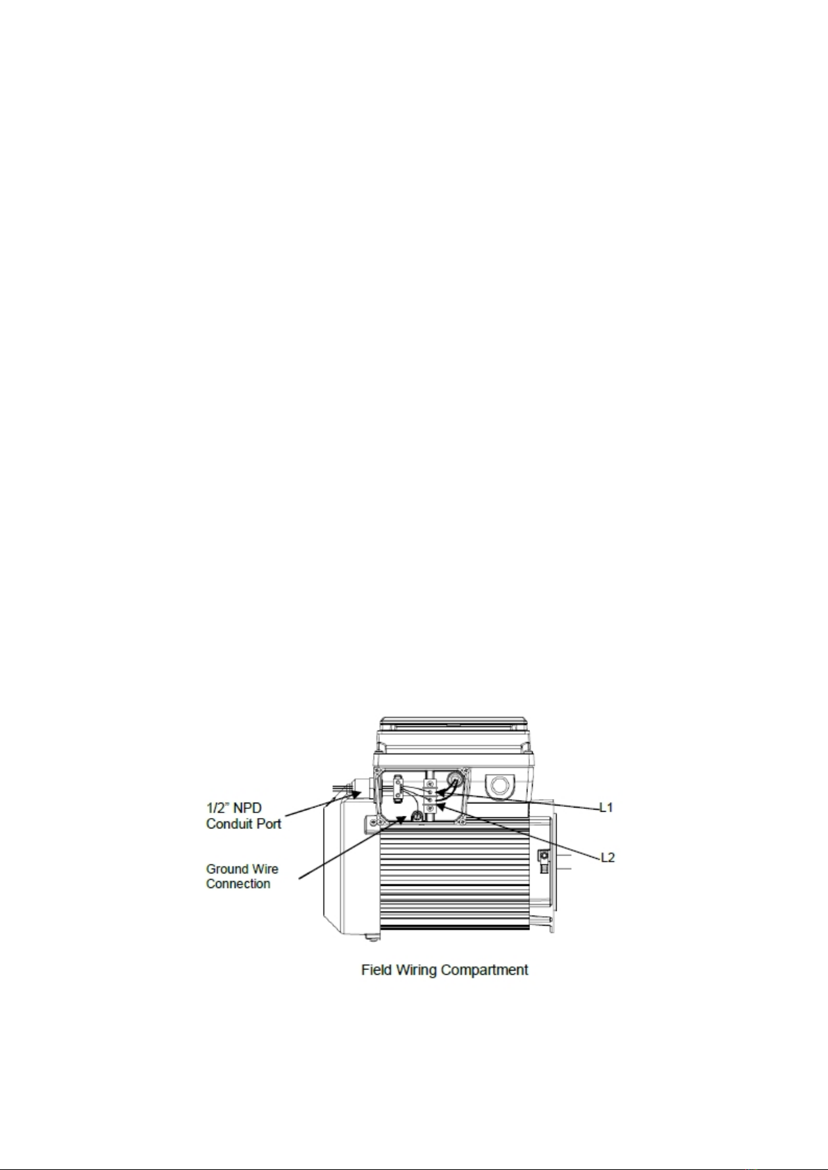
Note: ALWAYS reinstall the lid onto the field wiring compartment when leaving the pump
unsupervised during servicing. This will prevent foreign matter (i.e. rainwater, dust, etc.) from
accumulating in the field wiring compartment.
Wiring
1. Be sure all electrical breakers and switches are turned off before wiring motor.
STORED CHARGE - Wait at least sixty (60) Seconds before servicing.
2. Be sure that the supply voltage meets the requirements listed on the motor nameplate. If
these requirements are not met, permanent motor damage may occur.
3. For wiring sizes and general guidelines for proper electrical installation, please follow the
specifications
defined in the National Electric Code and any local codes as required.
4. Use strain relief and be sure all electrical connections are clean and tight.
5. Cut the wires tothe appropriate length so they do not overlap or touch when connected.
6. Reinstall the keypad cover after wiring the pump plugging the cover back into the drive
wiring connection and re-seating the keypad cover in the desired orientation with the four (4)
corner screws.
Note: Ensure that the keypad cable is not pinched between the drive and keypad cover during
re-seating.
5

6
Grounding
1. Permanently ground the motor using the green ground screw, as shown below. Use the
correct wire size and type specified by National Electrical Code. Be sure the ground wire is
connected to an electrical service ground.
2. The pump should be permanently connected to a circuit breaker, 2-pole timer or 2-pole relay
Note: If AC power is supplied by a GFCI circuit breaker, the pump should be wired on its own
independent circuit unless the pump is operated in tandem with a salt chlorine generator.
Bonding
Bond the motor tothe structure in accordance with the National Electrical Code. Use a solid
copper bonding conductor not smaller than 8 AWG. For Canadian installations, a 6 AWG or
larger solid copper bonding conductor is required. Run a wire from the external bonding screw
or lug tothe bonding structure.
2. Connect the wire from the accessible bonding lug on the motor to all metal parts of the
swimming pool, spa, or hot tub structure and to all electrical equipment, metal conduit, and
metal piping within 5 feet (1.52 meters) of the inside walls of the swimming pool, spa, or
hot tub. Run a wire from the external bonding screw or lug tothe bonding structure.
Note: When the pump is started and stopped by removing power with a relay or timer, a
two-pole device should be used
to apply and remove power to both POWER LINE TERMINALS. While meeting 2008 to current
NEC Standards for Pool Pumps.
PRODUCTIONINTRODUCTION
This variable speed pump is designed to operate your swimming pool filtration system
as well as your spa, waterfall, cleaner, heater, salt chlorine system and other water
applications.
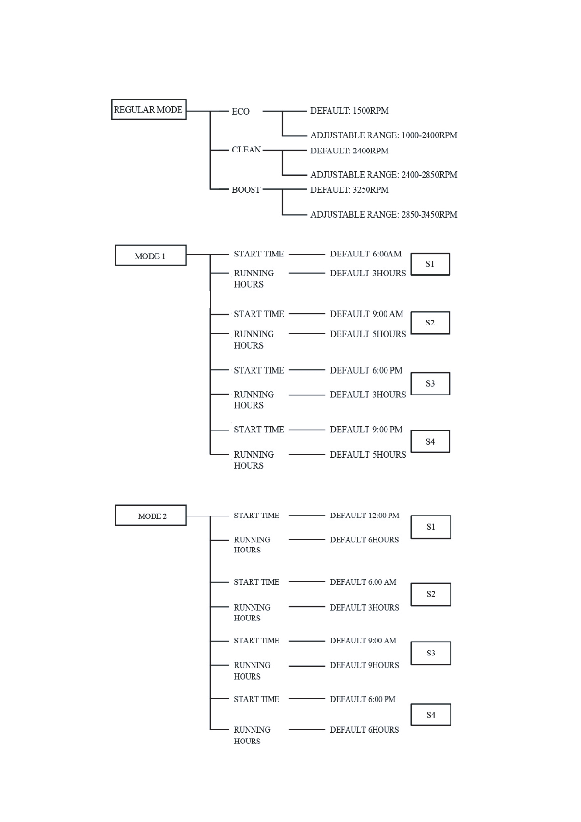
Using the control panel, you can run your pump on one of three scheduled programs:
1. Regular mode: use three quick start buttons.
ECO (default 1500RPM)/CLEAN (default 2400RPM)/ BOOST (default 3250RPM), and then
adjust the pump torunat the speeds you selected.
2. Mode 1: 16 hour s for each clean cycle.
3. Mode 2: 24 hour s for each clean cycle.
The control pane l also has LED indicators for speed as well as alarm indicators and error
messages towarn the user against under and over voltage, high temperature, over current
and freeze protection.
1. Features of LEDControl Pane l
1!Display and changetime
2!Display and changerunning speed
3!Quick-start button of ECO/CLEAN/BOOST to run on different speed
4!MODE1/MODE2 for scheduled program (16 hours or 24 h ours clean cycle)
5!Re-start and reset to normal schedule after over current, over voltage, over heat, or
unexpected power off.

6!Keep records of scheduled programs for maximally 15 days after power off.
7!Run 5 minutes high speed when first start the pump
8!Step-by-step acceleration and deceleration of the speed to extend the use life of the
motor and control panel
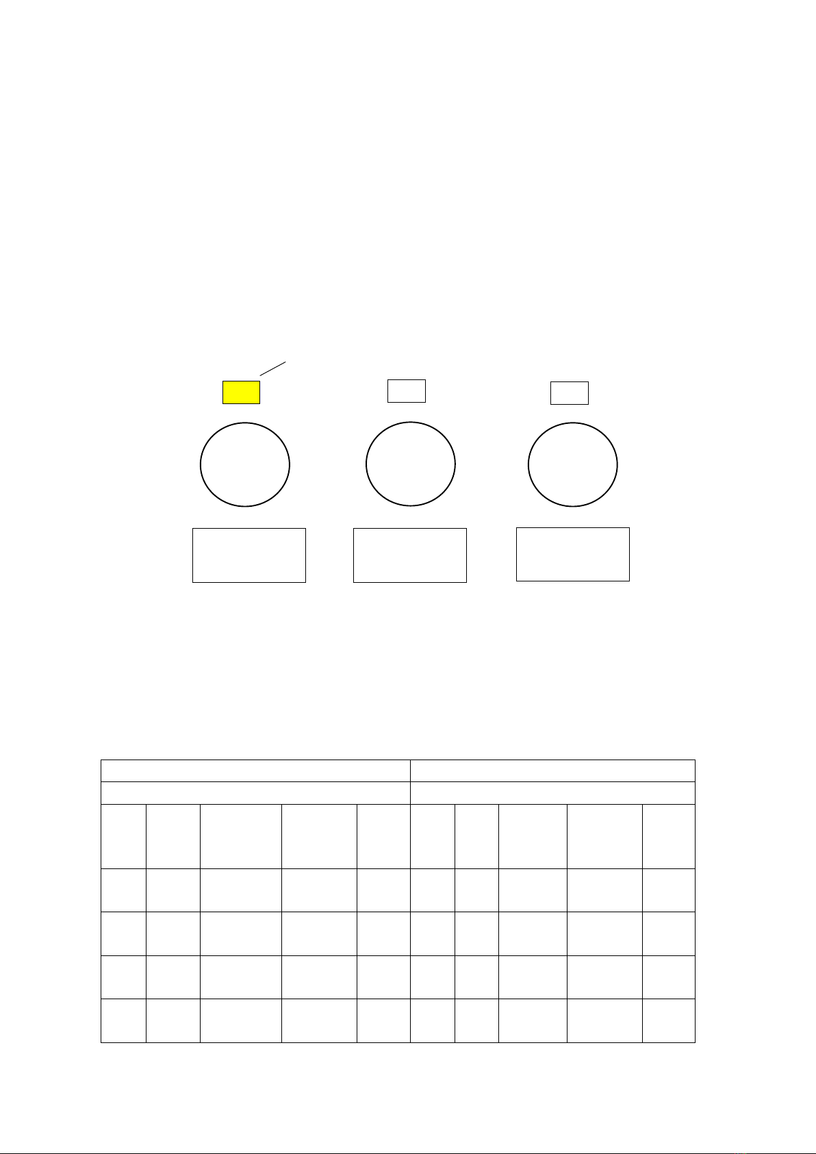
2. Introduction of LED Control Board
!ECO: Press to select and run on default speed 1500 PRM, can adjust from 1000 to 2400
RPM
"CLEAN: Press to select and run on default speed 2400 PRM, can adjust from 2400 to 2850
RPM
#BOOST: Press to select and run on default speed 3250 PRM, can adjust from 2850 to 3450
RPM
$STOP: Press to stop the pump. The screen displays the present time
%MENU: Accesses the pump menu ifthe pump is stopped
&MODE 1: To run the programmed 16 hours clean cycle.
'MODE 2: To run the programmed 24 hours clean cycle.
(Enter: Save and exit the menu.
)ARROW BUTTONS:
•UP ARROW –Move up on e level in the menu or to increase a digit when changing a
setting
•DOWN ARROW –Move one level down in the menu or to decrease a digit when
changing a setting.
•LEFT ARROW –Moves the cursor left one digit when changing a setting
•RIGHTARROW –Movesthe cursor right one digit when changing a setting
*LED Screen: Composed of four digital tubes. Display current time when in standby. And
display the current and running speed back and forth in operation.
+AM/PM: Designed for 12-hours system. If pump run on 0:0 0 -11:59, AM light on ;
run on 12 :00 - 23:59, PM light on.
,MODE1 and MODE 2 have 4 stages, S1/S2/S3/S4 is the speed for each stage. Ifthe S1
light is on, the pump is run on first stage, if the light twinkles, the time for the stage is not
arriving yet or the pump is no t running. If SPEED light is on, the screen will display the current
RPM. If HOUR light twinkles; you are ready to set the running time for each stage. If ALARM
light is on, an alarm condition exists.
-Press MODE 1,the light will be lit and one light of S1/S2/S3/S4 will be on or twinkle.
(Light twinkle means the current time is no t du ring the set running period), and on e of AM or
PM light will be on.
.Press MODE2, the light will be lit and the one light of S1/S2/S3/S4 will be on o r
twinkle.(Light twinkle means the current time is not during the set running period), and one of
AM or PM light will on.
/When the pump is in standby switch MODE 1andMODE2, the corresponding light will be
lit, and the pump run accordingly.
7

3.Stop And Run The Pump
3.1 Start the Pump
1) Make sure the pump is connected with electricity. When power is on, the display screen will
display the time.
2) Press one of ECO/CLEAN/BOOST, the pump will run. The light on the corresponding
program will be lit. Nomatter what program you select, the pump will run on 2850RPM for 5
minutes to eliminate the air in the pump, so the impeller will not dry grind thus to cause leakage.
After high-speed running, the pump will run the default speed of the selected program.
3.2 Stop the Pump
Press STOP of the running pump, the pump will stop. The lights on the screen twinkle.
3.3 Change Pump Running Speed
1) When the pump is running ECO/CLEAN/BOOST, press arrow buttons up or down to change
the speed, each press is for 50RPM. It will save automatically, no need to press ENTER.
2) Switch ECO/CLEAN/BOOST during pump operation, the pump will not run 5 minutes high
speed again.
3) For MODE 1 and MODE 2, to change speed of S1 and S3, first press CLEAN, if not
work, you will need to stop the pump first. After 5 minutes high speed running, press
CLEAN, then press arrow button to increase or decrease RPM. When press MODE 1 or
MODE 2 again torun the pump, S1 and S3 will run as just selected.
To adjust S2 and S4, first press ECO, if not work, you will need to stop the pump. After
10 minutes high speed running, press ECO, then press arrow button to increase or decrease
RPM. When press MODE 1 or MODE 2 again, S2 and S4 will run as just selected.
8
10
7
8
4
3
2
1
5
9
6
9
NOTE: PRM for S2 and S4 or S1 and S3 are always the same.
The default for S1 and S3 is2400RPM, the adjustable range is 2400 to 2850RPM.
The default for S2 and S4 is 1500RPM.The adjustable range is 1000 to 2400PRM.
3.4 Pump Run Under Pre -programmed Conditions
Pump has three quick start button ECO/CLEAN/BOOST, as below figure. The default speed is
1500, 2400, 3250RPM respectively.
1) Be sure the pump is power on.
2) Press one of ECO/CLEAN/BOOST, the LED light on screen will be lit.
3) The screen will display STOP for 1 second, and run 2850PRM for 5 minutes. After 10
minutes, the pump will run on the selected speed.
4. Pump Run under MODE1/MODE2
4.1 MODE 1/MODE2 Introduction
MODE 1 MODE 2
16 hours running cycle 24 hours running cycle
Stage Start
Time
Running Hour Default
Speed
Quick
Start
Button
Stage Start
Time
Running
Hour
Default
Speed
Quick
Start
Button
S1 6:00AM 3
(adjustable)
2400RPM
(adjustable)
CLEAN S1 12:00
PM
6
(adjustable)
1500PM
(adjustable)
ECO
S2 9:00AM 5
(adjustable)
1500PM
(adjustable)
ECO S2 6:00
AM
3
(adjustable)
2400RPM
(adjustable)
CLEAN
S3 6:00PM 3
(adjustable)
2400RPM
(adjustable)
CLEAN S3 9:00
AM
9
(adjustable)
1500PM
(adjustable)
ECO
S4 9:00PM 5
(adjustable)
1500PM
(adjustable)
ECO S4 6:00
PM
6
(adjustable)
2400RPM
(adjustable)
CLEAN
1000-2400RPM
DEFAULT: 1500
CLEAN
2400-2850RPM
DEFAULT: 2400
2850-3450RPM
DEFAULT: 3250
ECO BOOST
Indicator Light

10
4.2 How to Set and Change Specification of MODE1/MODE2
1) Make sure STOP button is pressed before set up, and pump is not working. Press MENU,
LED screen will display the current time (time will not count during set-up), use arrow buttons
to adjust the time. LEFT and RIGHT to move the cursor one digit, and UP and DOWN to
increase or decrease one digit.
(Remarks: 0:00-11:59 is one cycle). For example, the current time is 6:00 and AM light
is lit, when change the time after 11:59, the time change to 0:00, PM light will be lit.
2) After time set-up, press ENTER to save and exit.
Don't press ENTER if to continue change the specification of MODE1 and MODE 2.
Press MENU again, the light of MODE 1 and S1 will be lit, screen display 6:00, and
AM light is lit. Use arrow buttons to adjust the time. Whenthe time is over 11:59, PM
light will be lit, AM light extinguished.
3) Press ENTER to save and exit after start time set-up. To continue and adjust the
running hour, press MENU, then use arrow buttons to increase and decrease running
hours. Each press is for 1 hour. Press ENTERto save and exit. Or press MENUto
adjust S2/S3/S4, the same adjustment method as S1.
4) Follow MODE 1's adjustment methods to adjust MODE 2.
5) Could not change speed using arrow buttons whenrunning MODE1/MODE2. Can
only change the speed of MODE 1 and MODE 2 by pressing CLEAN/ECO/BOOST,
and then use arrow button UP and DOWN to change the RPM. When it is done, the
corresponding speed in MODE 1/MODE 2 will also change.
You could only change according tothe matching quick start button. For example, in
MODE 1, S1 and S3 isCLEAN, S2 and S4 is ECO; inMODE 2, S1 and S3 isECO, S2
and S4 is CLEAN.
5. How toOperate the Pump?
Totally three pre-programmed schedules: Regular Mode (including ECO; CLEAN; BOOST)
and MODE 1/MODE2.
1000-2400RPM
DEFAULT: 1500
CLEAN
2400-2850RPM
DEFAULT: 2400
2850-3450RPM
DEFAULT: 3250
ECO BOOST
Indicator Light
11

12
6. Control Panel Menu Structure

7.Alert and Warnings
The pump displays all alerts and warnings on the control panel. When an alarm or warning
condition exists, the corresponding LEDswill be lit on the display. All control panel buttons are
disabled until the alarm or warning is acknowledged with the ENTER button. Disconnect power
to the pump and wait untilthe screen has all turned off.
POWER OUT FAILURE–Incoming supply voltage is less than 190 VAC.
PRIMING ERROR –Ifthe pump is not defined as primed within the maximum priming time it
will stop and generate a priming alarm for 10 minutes, then attempt to prime again. If the pump
cannot prime within 5 attempts it will generate a permanent alarm and have to be manually
reset.
OVERHEAT ALERT –If the drive temperature gets over 103 Degrees Fahrenheit the
pump will slowly reduce speed until the drive temperature condition drops.
OVER CURRENT –Indicates that the drive is overloaded or the motor has an electrical
problem. Ifthey do not clear after multiple restart attempts the drive should undergo a hard
power cycle. Disconnect main power by turning off the breaker long enough for the keypad
LEDs toturn off. After power is reconnected if this error continues toreappear, the drive may
need service.
OVER VOLTAGE –Indicates excessive supply voltage or and external water source is
causing the pump and motor torotate thereby generating excessive voltage in the drives
internal DC bus. Ifthey do not clear after multiple restart attempts the drive should undergo a
hard power cycle. Disconnect main power by turning off the breaker long enough for the
keypad LEDstoturn off. After power is reconnected if this error continues toreappear, the
drive may need service.
1.Alert Code Details
Code Error Remarks
1 Get blocked or short circuit overheat
2 Voltage input exceeds limit
4 High input voltage
8 Low input voltage
16 Exceeds maximum speed
32 Speed is 0
64 Motor phase loss
128 Abnormal start-up
256 System configuration error
512 Stall at startup
1024 System operation error Contact the manufacturer
4096 Hardware test error Contact the manufacturer
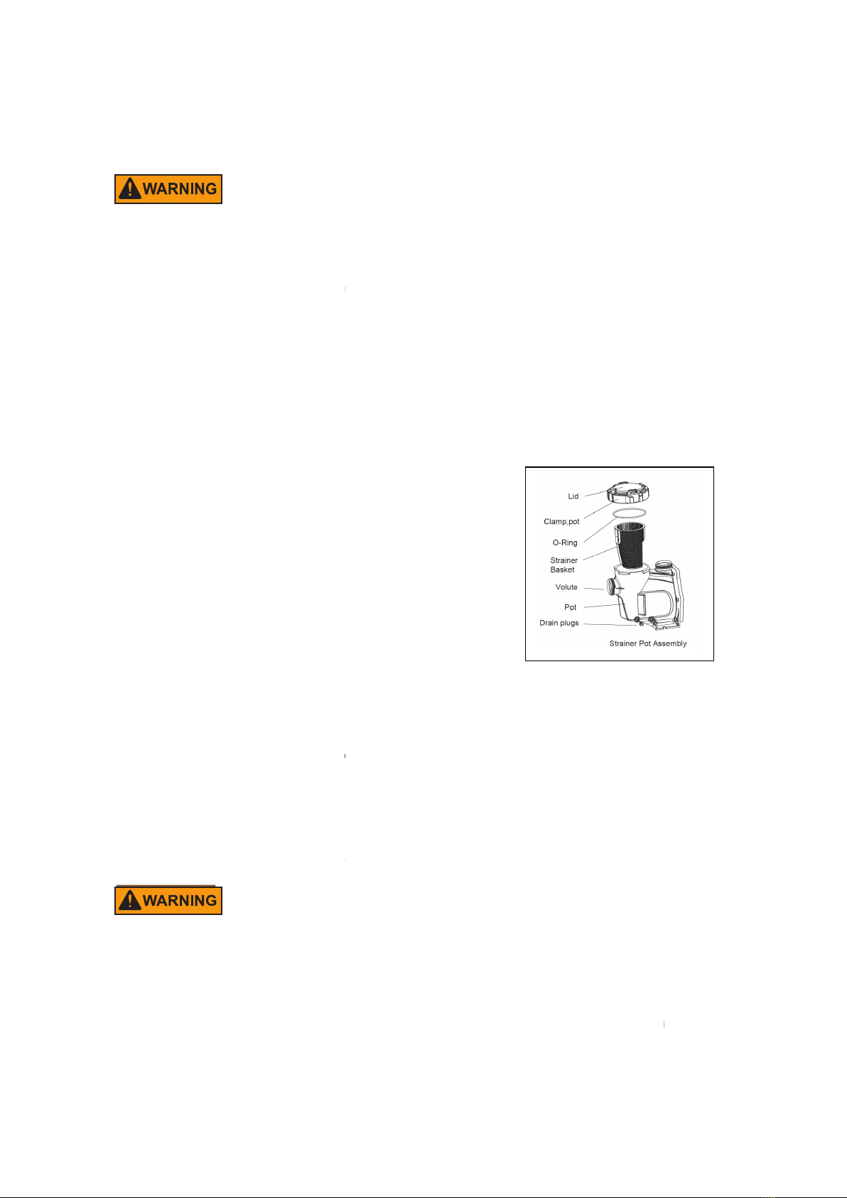
8.Priming
The pump will prime and pre-prime providing the filter tank water and there is sufficient supply
from the suction point.
If you lose water from the filter tank it will be necessary tore-fill it before starting.
1. Remove the translucent lid and fill the filter tank withwater.
13
2. Replace the lid ensuring the o-
ring is correctly located and start the pump.
After you have done this allow a few minutes (maximum) running for the pump to start
delivering water.
High suction lift or long suction lines will require additional time to prime and can severely
affect the performance of the pump. Ifthe pump does not
above. Mechanical seals ifrunning dry can be damaged rapidly and may need tobereplaced.
ENSURE that there is always adequate water in the filter tank before you start up.If you are
unable to prime the pump please see t
ENSURE that all suction and discharge valves are open before you start the pump, otherwise
will result in damage tothe pump.
9.Maintenance
The strainer basket inthe filter tank should be inspected and cleaned at regular interv
1. Remove lid and lift out basket.
2. Remove debris and hose off with clean water if necessary.
3. Inspect the lid gasket, lubricate with silicon based grease
only if needed. If it is damaged, pls replace.
4. Replace the strainer.
5. Re-prime the filter tank.
6. Correctly locate the o-ring.
7. Replace the lid hand tighten
only.
8. Switch on pump.
In Climates where the pump may be exposed to frost or freezing,
the pump is protected from damage.
winter period it should be drained completely and store pump in a dry location. Do not replace
the drain plug. Store it in a safe place when not use. An example would be store plug in the
filter tank basket.
When you are activa
ted the pump ensures all seals and o
re-
grease if necessary, replaced if unsure of condition.
Checkthat the motor shaft moves freely before re
1. When connecting electric cables tothe motor of the pump,
them inside the connection box, verifythat no bits of cable are left inside the box on closing it.
See that the
ground wire is correctly connected.
diagram supplied with the pump.
2. Be especially careful
that no water enters the motor or electrical parts under voltage.
3. Inthe event that the planned use is not as specified, adaptations and supplementary
technical rules may be necessary.
ring is correctly located and start the pump.
After you have done this allow a few minutes (maximum) running for the pump to start
High suction lift or long suction lines will require additional time to prime and can severely
affect the performance of the pump. Ifthe pump does not
prime, please repeat step 1 and 2
above. Mechanical seals ifrunning dry can be damaged rapidly and may need tobereplaced.
ENSURE that there is always adequate water in the filter tank before you start up.If you are
unable to prime the pump please see t
he trouble-shooting guide.
ENSURE that all suction and discharge valves are open before you start the pump, otherwise
The strainer basket inthe filter tank should be inspected and cleaned at regular interv
2. Remove debris and hose off with clean water if necessary.
3. Inspect the lid gasket, lubricate with silicon based grease
only if needed. If it is damaged, pls replace.
only.
In Climates where the pump may be exposed to frost or freezing,
c
are must be taken to ensure
the pump is protected from damage.
It is recommended that if
the pump is not used during
winter period it should be drained completely and store pump in a dry location. Do not replace
the drain plug. Store it in a safe place when not use. An example would be store plug in the
ted the pump ensures all seals and o
-
rings are in operational condition,
grease if necessary, replaced if unsure of condition.
Checkthat the motor shaft moves freely before re
-activation.
1. When connecting electric cables tothe motor of the pump,
be careful to correctly arrange
them inside the connection box, verifythat no bits of cable are left inside the box on closing it.
ground wire is correctly connected.
When connecting the motor, follow the wiring
that no water enters the motor or electrical parts under voltage.
3. Inthe event that the planned use is not as specified, adaptations and supplementary
After you have done this allow a few minutes (maximum) running for the pump to start
High suction lift or long suction lines will require additional time to prime and can severely
prime, please repeat step 1 and 2
above. Mechanical seals ifrunning dry can be damaged rapidly and may need tobereplaced.
ENSURE that there is always adequate water in the filter tank before you start up.If you are
ENSURE that all suction and discharge valves are open before you start the pump, otherwise
The strainer basket inthe filter tank should be inspected and cleaned at regular interv
als.
are must be taken to ensure
the pump is not used during
winter period it should be drained completely and store pump in a dry location. Do not replace
the drain plug. Store it in a safe place when not use. An example would be store plug in the
rings are in operational condition,
be careful to correctly arrange
them inside the connection box, verifythat no bits of cable are left inside the box on closing it.
When connecting the motor, follow the wiring
that no water enters the motor or electrical parts under voltage.
3. Inthe event that the planned use is not as specified, adaptations and supplementary
14

4. Before starting the pump, verifythe c
motor and that
the protections against electrical and mechanical contacts are correctly
positioned and attached.
5. It is advisable to follow the steps listed below before handling the pump in any way.
a) Turn off the voltage tothe pump.
b) Lock starting devices.
c) Verify that there is no voltage in the circuits, including ancillary devices and auxiliary circuits.
d) Wait until motor stops completely.
The above list should be considered indicative and
specific safety
rules may exist in particular regulations.
Assembly Instructions (some parts may be pre
Follow the step below and the corresponding diagrams for assembly.
Step 1.
Place the strainer baske
t tothe strainer housing. Be sure that the opening the basket is
aligned with the opening inthe housing. Secure Lid
Step 2.
The water level of the inground
swimming
In order to prevent water from
flowing
First screw the adapter into the
water
assembly.
Step 1 Step 2
REGULARLY VERIFY
1. The correct a
ttachments of the mechanical parts and of the support screws of the pump.
2. The correct position, attachment and condition of the supply cables and of the insulating
parts.
3. The temperature of the motor. Inthe event of any excessive high, stop immediat
have it repaired.
4. The vibration of the pump. Inthe case of any excessive high, stop immediately and have it
repaired.
4. Before starting the pump, verifythe c
alibration of the electrical protection devices of the
the protections against electrical and mechanical contacts are correctly
5. It is advisable to follow the steps listed below before handling the pump in any way.
a) Turn off the voltage tothe pump.
c) Verify that there is no voltage in the circuits, including ancillary devices and auxiliary circuits.
d) Wait until motor stops completely.
The above list should be considered indicative and
not binding for the purpose of safety,
rules may exist in particular regulations.
Assembly Instructions (some parts may be pre
-assembled)
Follow the step below and the corresponding diagrams for assembly.
t tothe strainer housing. Be sure that the opening the basket is
aligned with the opening inthe housing. Secure Lid
swimming
pool is lower than the water inlet of the
pump.
flowing
backward, this pump equipped a check
valve.
water
inlet of the pump, and then install the
connector
Step 1 Step 2
ttachments of the mechanical parts and of the support screws of the pump.
2. The correct position, attachment and condition of the supply cables and of the insulating
3. The temperature of the motor. Inthe event of any excessive high, stop immediat
ely and
4. The vibration of the pump. Inthe case of any excessive high, stop immediately and have it
Please ensure this direction
towards the pump
alibration of the electrical protection devices of the
the protections against electrical and mechanical contacts are correctly
5. It is advisable to follow the steps listed below before handling the pump in any way.
c) Verify that there is no voltage in the circuits, including ancillary devices and auxiliary circuits.
not binding for the purpose of safety,
t tothe strainer housing. Be sure that the opening the basket is
pump.
valve.
connector
ttachments of the mechanical parts and of the support screws of the pump.
2. The correct position, attachment and condition of the supply cables and of the insulating
ely and
4. The vibration of the pump. Inthe case of any excessive high, stop immediately and have it
15

16
CAUTION
Owing tothe complexity of the cases covered, the instructions for installation, use and
maintenance contained inthis manual do not attempt to examine all possible and imaginable
cases of service and maintenance. If supplementary instructions are required or if special
problems arise, do not hesitate to contact the distributor or to address directly the
manufacturer of the pump.
TECHNICAL DATA
Item CSPPV711
Input Power 125w
H. Max 59ft
Q. Max/min 366L
V 230
HZ 50/60
IP IPX5

17
ILLUSTRATED PARTS LIST
Ref.No. Part. No. Description QTY Remark
1 647253571 Cover 1
2 65431042080 O-Ring 1
3 647252704 Basket 1
4 647253501 Pump Housing 1
5 65431032080 O-Ring 1
6 65212025000 Screw ST4.2*38 2
7 647254703 Diffuser 1
8 647274871000 Impeller For CSPPV711 1
9 65431168080 O-Ring 1
10 65028014000 Seal Assembly 1
11 647254702 Pump Cover 1
12 65244015000 Gasket M10 10
13 65244032000 Spring Washer M10 6
14 65225003000 Screw 3/8-16*1 1/2 UNC 6
15 65023399000 Variable Speed 1.5HP Motor For CSPPV711 1
16 65221008000 Screw M10*25 4
17 65232001106 Nut 3/8-16 6
18 65432002080 Drain Plug Gasket 2
19 648860105 Drain Plug 2
20 65231002106 Nut M6 2
21 65244016000 Gasket M6 2
22 65224003000 Screw M6*20 2
23 647254704 Mounting Foot 1
24 647254705 Supporting Foot 1
25 647253572001 1.5''Adaptor Assembly 2
26 647253573000 Check Value 1

18
TROUBLESHOOTING
Problem Cause Solution
Low flow Dirty filter Backwash or clean cartridge
Dirty skimmer and pump
strainer
Clean skimmer and pump strainer
Suction air leak Make sure water level is correct through suction
points. Ensure baskets and strainers are free of
debris. Tighten all fittings/unions on the suction
side of the pump, remove and replace mechanical
seal
Closed valve or blocked
line
Make sure water level is correct through suction
points. Ensure baskets and strainers are free of
debris. Tighten all fittings/unions on the suction
side of the pump, remove and replace mechanical
seal
Pump does
not run
Not plugged in Checkthe socket and power cord
GFCI/or main circuit
breaker tripped
Switch on the breaker. If it is immediately tripped
again,
There is a defect in pump or controls.
Faulty Pump shaft /motor Replace the pump/motor assembly.
Pump shaft is locked Checkifthe pump can be rotated by hand and
remove any blockage
Pump will not
prime
Suction air leak Make sure water level is correct through suction
points. Ensure baskets and strainers are free of
debris. Tighten all fittings/unions on the suction
side of the pump, remove and replace mechanical
seal
No water in the pump Make sure the filter tank is full
Closed valves or blocked
lines
Open all valves in the system, clean skimmer and
pump basket, check pump impeller of blockage
Motor
overload cuts
out
Motor not connected
properly
Have electrician check wiring
Low incoming voltage Voltage at motors should be no more than 6%
above or below nameplate voltage. Have
electrician check voltage; ensure pump is not
running on an extension cord. Report low supplier
to authorities.
Overload due to binding
in pump or wrong size
impeller
Contact supplier
Noise pump
operation
Bad bearing Have electrician replace
Air leak in suction Make sure water level is correct through suction
points. Ensure baskets and strainers are free of

debris. Tighten all fittings/unions on the suction
side of the pump, remove and replace mechanical
seal
Suction blockage Locate and clean blockage
Disturbance inimpeller Contact supplier
Cavitations Improve suction, reduce suction lift, reduce number
of fittings, increase pipe size, increase discharge
pressure and reduce flow by throttling discharge
valve
Motor runs
hot
Low or incorrect voltage Supply to be corrected by electrician. A motor
running hot totouch is normal. Thermal overload
protector will function toturn them off ifthere is an
overload or excessive high temperature problem
Installed in direct
sunlight
Shield from weather
Poor ventilation Do not tightly cover or enclose motor
If the pump iswithin the stated warranty period and you experience faults always contact your
supplier. Failure todothis may void warranty. Refer to warranty documentation supplied with
pump. All electrical work is to be carried out by a Qualified Electrician; under no circumstances
should you attempt repairs on the electrical components of pumps unless you are qualified to
do so.
19
Table of contents
Popular Water Pump manuals by other brands

Beckett
Beckett Fountain Pump M60AUL Specifications

Wilo
Wilo Wilo-Rexa PRO-S Installation and operating instructions

Alentec & Orion
Alentec & Orion 52510 user manual

Pentair
Pentair MYERS 7360 Installation and service manual

EarthQuake
EarthQuake WP4310 Operator's manual

GORMAN-RUPP PUMPS
GORMAN-RUPP PUMPS SF6E Installation, operation, and maintenance manual with parts list

Pentair
Pentair JUNG PUMPEN PKS-B 800 Series instruction manual

Exhausto
Exhausto CONPUMP-AS Product information

Raider
Raider Garden Tools RD-WP 1300 user manual

Oase
Oase Aquarius 1500 Operation instructions

BRÖTJE
BRÖTJE HEP 25-180-10 Assembly instructions

Wilo
Wilo Drain LP 40 Installation and operating instructions


