Circa Enterprises Inc. Guardian Telecom ACR-VoIP Series Owner's manual

Ph: 403.258.3100 \ email:info@guardiantelecom.com \ www.guardiantelecom.com
Heavy Duty Weather Resistant VoIP Telephones
ACR-VoIP and ACT-VoIP Series
Installation and Operation
ACT-30-VoIP ACR-41-VoIP
P007312 Rev. E 180914 9/14/2018 10:56 AM

Guardian Telecom Inc. Installation and Operation
ACR/ACT-VoIP Series Telephones
Page 2
PoE ACR/ACT-VoIP Installation Guide P007312 Rev. E
COPYRIGHT NOTICE:
© 2018, Guardian Telecom, ALL RIGHTS RESERVED.
This manual and the related materials are the copyrighted property of Guardian Telecom
No part of this manual or related materials may be reproduced or transmitted, in any form
or by any means (except for internal use by licensed customers), without prior express
written permission of Guardian Telecom This manual, and the products, software,
firmware, and/or hardware described in this manual are the property of Guardian Telecom
provided under the terms of an agreement between Guardian Telecom and the recipient
of this manual, and their use is subject to that agreement and its terms.
DISCLAIMER: Except as expressly and specifically stated in a written agreement
executed by Guardian Telecom, Guardian Telecom makes no representation or warranty,
express or implied, including any warranty or merchantability or fitness for any purpose,
with respect to this manual or the products, software, firmware, and/or hardware described
herein, and Guardian Telecom assumes no liability for damages or claims resulting from
any use of this manual or such products, software, firmware, and/or hardware. Guardian
Telecom reserves the right to make changes, without notice, to this manual and to any
such product, software, firmware, and/or hardware.
OPEN SOURCE STATEMENT: Certain software components included in Guardian
products are subject to the GNU General Public License (GPL) and Lesser GNU General
Public License (LGPL) “open source” or “free software” licenses. Some of this Open
Source Software may be owned by third parties. Open Source Software is not subject to
the terms and conditions of the Guardian COPYRIGHT NOTICE or software licenses.
Your right to copy, modify, and distribute any Open Source Software is determined by the
terms of the GPL, LGPL, or third party, according to who licenses that software.
Software or firmware provided by Guardian that is unrelated to Open Source Software is
copyrighted by Guardian, subject to the terms of Guardian licenses, and may not be
copied, modified, reverse-engineered, or otherwise altered without explicit written
permission from Guardian Telecom
TRADEMARK NOTICE: Guardian Telecom and the Guardian Telecom logos are
trademarks of Guardian Telecom Other product names, trademarks, and service marks
may be the trademarks or registered trademarks of their respective owners.
Toll-free 1-800-363-8010
Phone (403) 258-3100
Fax. (403) 253-4967
www.guardiantelecom.com
E-mail: [email protected]
Guardian Telecom Inc. Installation and Operation
ACR/ACT-VoIP Series Telephones
Page 3
Important Safety Instructions
1. Read these instructions.
2. Keep these instructions.
3. Heed all warnings.
4. Follow all instructions.
5. Install in accordance with the manufacturer’s instructions.
6. Do not install near any heat sources such as radiators, heat registers, stoves, or other
apparatus (including amplifiers) that produce heat.
7. Only use attachments/accessories specified by the manufacturer.
8. Refer all servicing to qualified service personnel.
9. Prior to installation, consult local building and electrical code requirements.

Guardian Telecom Inc. Installation and Operation
ACR/ACT-VoIP Series Telephones
Page 4
Table of Contents
1. Product Overview.......................................................................................................6
2. Typical System Installation.........................................................................................6
3. Features.....................................................................................................................7
4. Installation................................................................................................................10
5. Operation..................................................................................................................10
6. Supported Protocols.................................................................................................11
7. Supported SIP Servers.............................................................................................11
8. ACR/ACT-VoIP Telephones Wiring..........................................................................11
8.1. Connections..................................................................................................11
8.2. Connecting a Device to the Auxiliary Relay..................................................12
8.3. Identifying the Connector Locations and Functions ......................................13
8.4. Network Connectivity, and Data Rate...........................................................14
8.4.1. Verify Network Activity..........................................................................14
8.5. RESET Switch ..............................................................................................15
8.5.1. Announcing the IP Address..................................................................15
8.5.2. Restore the Factory Default Settings....................................................15
8.6. Adjust the Volume.........................................................................................15
9. Specifications...........................................................................................................16
10. Field Repairs............................................................................................................17
11. Replacement Parts...................................................................................................18
12. Warranty...................................................................................................................19
13. Disclaimer.................................................................................................................19
14. Warning....................................................................................................................19
15. Service Telephone Number......................................................................................19
16. Feedback..................................................................................................................19
17. Guardian Product Return..........................................................................................20
18. Cleaning Tips for Guardian Telephones...................................................................21
19. Storage.....................................................................................................................21
Figures
Figure 1 - Typical Installation..............................................................................................6
Figure 2 - Features (typical)................................................................................................8
Figure 3 - Overall Dimensions.............................................................................................8
Figure 4 - Wiring .................................................................................................................9
Figure 5 - Terminal Block Connections.............................................................................11
Figure 6 - Connector Locations.........................................................................................13
Figure 7 - Network Activity................................................................................................14
Figure 8 - RESET Switch..................................................................................................15
Tables
Table 1 - Connector Functions..........................................................................................13

Guardian Telecom Inc. Installation and Operation
ACR/ACT-VoIP Series Telephones
Page 5
Package Contents
(1) ACR or ACT VoIP Telephone
Note: Installation and Operation Manual, Setup and Configuration Manual, Guardian
Discovery Utility, Interoperability Guide, VoIP Technical Support, Firmware and
Autoprovisioning template are all available at www.guardiantelecom.com.
Models
P5432 ACT-30-VoIP telephone with coil cord.
P5433ACT-40-VoIP telephone with armored handset cord.
P5434ACR-11-VoIP ringdown telephone with coil cord.
P5435ACR-41-VoIP ringdown telephone with armored handset cord.
Accessories
POE – Injector – Auxiliary Power Supply (Contact Sales)
Loud Ringers and Strobe Lights
Updating Your VoIP Product
Please review www.guardiantelecom.com support pages to obtain the latest F/W or contact

Guardian Telecom Inc. Installation and Operation
ACR/ACT-VoIP Series Telephones
Page 6
1. Product Overview
ACR-VoIP and ACT-VoIP Series Weather Resistant Telephones
The ACR-VoIP and ACT-VoIP Telephones meet the special requirements of sites prone to abuse and inclement weather. The
apparatus is housed in an aluminum enclosure with a locking or non-locking door. The unit resists moisture, dust and
corrosive chemicals and is specifically designed to provide reliable service in outdoor environments.
These telephones are compatible with most SIP-based IP PBX servers that comply with SIP RFC 3261. Users can remotely
monitor and program settings through a web browser to configure telephones on their network.
The ACR-11-VoIP and ACT-30 are standard models with a curly cord and the ACR-41-VoIP and ACT-40 are vandal resistant
models with an armored handset cord.
2. Typical System Installation
The Voice-over-IP (VoIP) ACR-VoIP and ACT-VoIP Telephones are Power-over-Ethernet (PoE 802.3af) and Voice-over-IP
(VoIP) two-way communications devices that easily connect into existing local area networks (LANs) with a single cable
connection.
Figure 1 illustrates how the ACR-VoIP and ACT-VoIP Telephones can be installed as part of a VoIP phone system.
Figure 1 - Typical Installation

Guardian Telecom Inc. Installation and Operation
ACR/ACT-VoIP Series Telephones
Page 7
3. Features
•Enclosure
-cast aluminum construction
-weather and dust resistant
-durable Hammertone grey powder coat paint
-locking or non-locking door
-nylon bushings provide smooth door operation
•Temperature range -22
˚
to +140
˚
F ( -30
˚
to +60
˚
C)
•Optional conformal coated circuit boards are
resistant to corrosive agents (e.g. H2S, SO2and NH3)
and environments with high humidity
•Waterproof connections & stainless steel fittings for
longer life
•Corrosion protected and powder coated steel
faceplate
•Magnetic Reed Hook Switch - no moving parts
•Easily mounted on any sturdy vertical structure
•Noise Reducing Microphone allows a high level of
intelligibility in locations with high background noise
•Armored Handset Cord (ACR-41-VoIP and
ACT-40-VoIP only) withstands severe use
•Heavy duty G Type industrial handset
•Handset retainers to maintain on-hook status
•Modular parts for easy service
•Hearing-Aid Compatible & Receiver Volume
Adjustment
•Compatible with inductively coupled hearing-aid
devices
•Adaptive full duplex operation
•Compatible with SIP-based IP PBX servers that
comply with SIP (RFC 3261).
•Network web management interface
•Guardian discovery utility makes it easy to detect,
locate and launch the web based configuration
screens
•Product self-diagnostic testing available through web
interface
•Network adjustable speaker volume and microphone
sensitivity sets default levels. User adjustable volume
control on Handset.
•PoE 802.3af enabled (Powered-over-Ethernet) or
alternate power source
•Web Based User Interface allows remote setup of
network, product operations, updates, self-
diagnostics and other functional access.
•Auxiliary Relay – Multiple activation selectable
through web interface.
•Dual speeds of 10 Mbps and 100 Mbps
•Network/Web management
•Dial Out Extension supports the addition of comma
delimited pauses before sending additional DTMF
tones
•Network downloadable product firmware
•Tamper proof design
•Autoprovisioning and Device Configuration
Export/Import saves setup time on multiple
deployments
•Configurable audio files
•Event Monitoring / Triggers – (Refer to VoIP
Configuration Guide – P/N: P007402)
•Three year warranty
•Peer-to-peer capable
•Optional security screws with driver bit
Guardian Telecom Inc. Installation and Operation
ACR/ACT-VoIP Series Telephones
Page 8
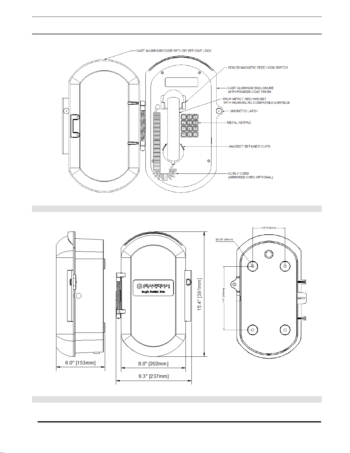
Figure 2 - Features (typical)
Figure 3 - Overall Dimensions

Guardian Telecom Inc. Installation and Operation
ACR/ACT-VoIP Series Telephones
Page 9
J1: STANDARD 8 PIN RJ45 10/100Base-T and power input via Power over Ethernet
Figure 4 - Wiring
Alternate Power – Pin 3 is positive and pin 4 is negative input.

Guardian Telecom Inc. Installation and Operation
ACR/ACT-VoIP Series Telephones
Page 10
4. Installation
Follow all appropriate electrical codes and use only approved electrical fittings for the
installation.
Determine if power to operate the telephone will be provided via the ethernet or if external power
will be required. If external power is required install Guardian’s Auxiliary Power Supply or
equivalent.
See: Figure 5 - Terminal
Block Connections
Choose a wall location that is free of obstructions and permits space for conduit or wire. See: Figure 3 - Overall
Dimensions
Ensure mounting can support 12 lbs. (5.5 kg) and any additional foreseeable load.
Ensure that none of the electrical connection circuits are live.
Open the door, remove the screws on the faceplate and remove the faceplate. Note: Be careful when
removing the faceplate. The
circuit board is on the
faceplate.
Disconnect the faceplate harness.
Use the template provided or the enclosure itself to locate and drill holes for mounting screws.
Secure the enclosure to the wall.
Bring the Ethernet cable into the enclosure through the conduit entrance and connect to the
RJ45 socket. If a conduit hub is used, ensure that it is grounded to the ground stud.
See: Figure 4 - Wiring
Connect external power if provided.
See: Figure 5 - Terminal
Block Connections
See: Section 8.2 Connecting
a Device to the Auxiliary
Relay
Connect the on board relay if utilized.
Reconnect the faceplate harness.
Ensure all connections are secure.
Determine that the telephone is properly connected by pressing the RESET switch for less than
five seconds to announce the IP address. LEDs on the RJ45 connector indicate network
connection and activity.
See: Section 8.5 RESET
Switch and Figure 7 -
Network Activity
Replace the faceplate.
Set up and configure if changes are required to the default settings.
See: Manual P007402 –
Setup and Configuration.
Test the unit by calling to and from another telephone.
5. Operation
Note: The details are
explained in the Setup and
Configuration Manual
P007402
ACT-VoIP telephones may be set up for either keypad dialing or auto-dialing.
If the telephone is configured for keypad dialing operation is identical to most other single line
telephones.
If the telephone is configured for auto dialing lift the handset and press the number assigned to
the extension to be dialed.
ACR-VoIP telephones will dial the programmed number when the handset is lifted.
Adjust the receiver volume with the switch in the handset.
Guardian Telecom Inc. Installation and Operation
ACR/ACT-VoIP Series Telephones
Page 11
6. Supported Protocols
The ACT-VoIP Telephone with Keypad supports:
●SIP (Session Initiation Protocol)
●HTTP Web-based configuration
Provides an intuitive user interface for easy system configuration, and verification of ACT-VoIP Telephone with
Keypad operations.
●DHCP Client
Dynamically assigns IP addresses in addition to the option to use static addressing.
●TFTP Client
Facilitates hosting for the Autoprovisioning configuration file.
●RTP
Facilitates autoprovisioning configuration values on boot.
●Audio Encodings
PCMU (G.711 mu-law)
PCMA (G.711 A-law)
G722.1 (Siren7)
G722.2 (AMR-WB)
G729.1 (G729J & G729EV)
7. Supported SIP Servers
As a SIP device, this product will operate with IP PBX servers.
8. ACR/ACT-VoIP Telephones Wiring
8.1. Connections
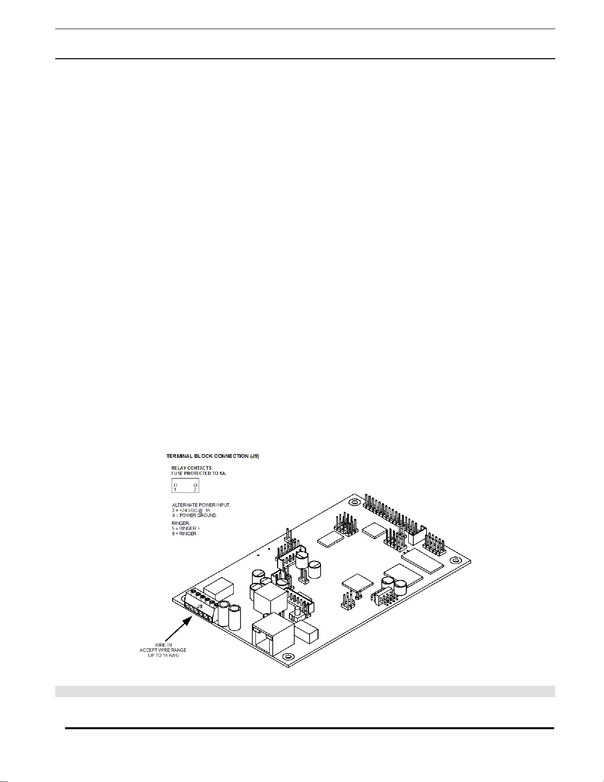
Figure 5 shows the pin connections on the J9 (terminal block). This terminal block can accept a wire range from 16
AWG to 26 AWG.
Note: As an alternative to using PoE power 24 VDC at 1A can be supplied to the terminal block.
Figure 5 - Terminal Block Connections

Guardian Telecom Inc. Installation and Operation
ACR/ACT-VoIP Series Telephones
Page 12
8.2. Connecting a Device to the Auxiliary Relay
The ACR/ACT-VoIP Telephone incorporates one on-board relay located on the PCBA, which
enables users to control a low current external relay or device. An external relay could control a
ringer, strobe light, door lock or any other apparatus. The on board relay is protected by a 1
Amp, non-replaceable fuse. Power switched by the relay should not exceed 0.5
Amps @ 30VDC. The PCBA is not designed to handle AC voltages.
Warning: The relay circuitry contains a non-replaceable 250VAC 1A fuse. If the
fuse blows the board must be returned to Guardian or an approved service
center for repair.
The Telephone relay activation time is selectable through the web interface on the Device
Configuration Page. The relay is controlled by DTMF tones generated from the phone to which
the VoIP phone is connected; no matter which one initiated the call. The DTMF tones are
selectable from the web interface as well.
See:Manual P007402
Setup and Configuration
Note: The three digit code for the auxiliary relay must be sent in conformance with RFC2833
DTMF generation.
Guardian Telecom Inc. Installation and Operation
ACR/ACT-VoIP Series Telephones
Page 13
8.3. Identifying the Connector Locations and Functions
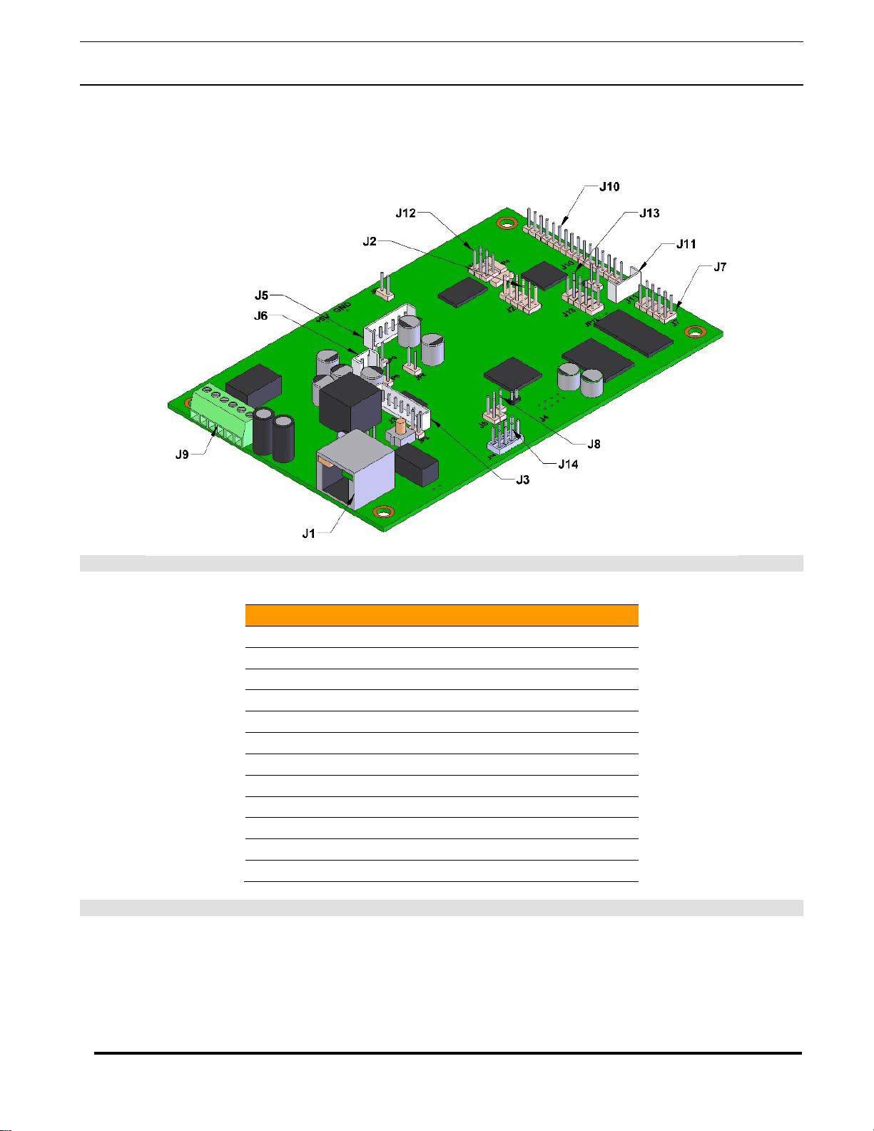
See Figure 7 and Table 1 to identify the connector locations and functions.
Figure 6 - Connector Locations
Connector
Function
J1 PoE Network Connection (RJ-45)
J2 Hands free Microphone Interface/LED Interface
J3 Not used
J4 JTAG Interface
J5 Handset/Reed Switch Interface
J6 Speaker Interface
J7 Keypad Interface
J8 RS232 Port
J9 Terminal Block (see Figure 5)
J10 Not used
J11 Handset V.C. Interface
J12 ISP-DIP/Debug UART
Table 1 - Connector Functions

Guardian Telecom Inc. Installation and Operation
ACR/ACT-VoIP Series Telephones
Page 14
8.4. Network Connectivity, and Data Rate
When you plug in the Ethernet cable or power supply:
• The square, green Link light above the Ethernet port indicates that the network connection has been
established (see Figure 8). The Link light changes color to confirm the auto-negotiated baud rate:
• This light is yellow at 10 Mbps.
• It is orange at 100 Mbps.
8.4.1. Verify Network Activity
The square, yellow Activity light blinks when there is network activity.
Figure 7 - Network Activity
Guardian Telecom Inc. Installation and Operation
ACR/ACT-VoIP Series Telephones
Page 15
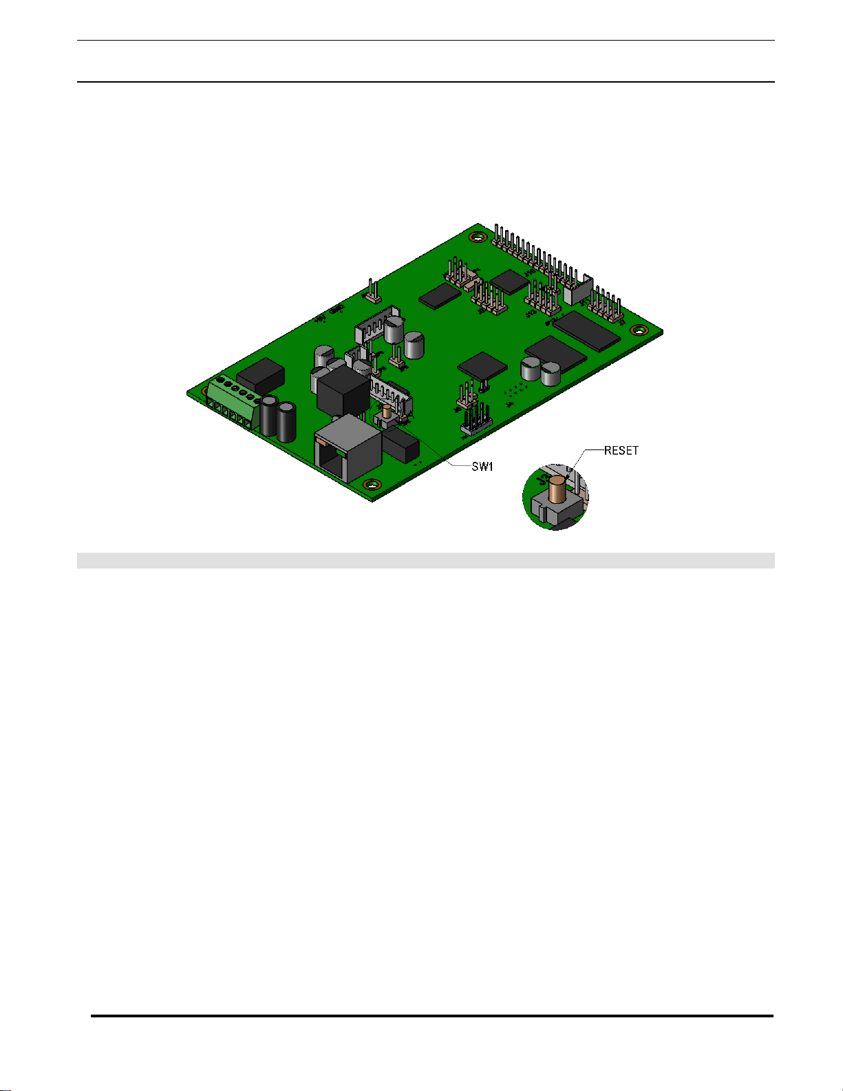
8.5. RESET Switch
When the Telephone is operational and linked to the network use the Reset Test Function Management
(RESET) switch (Figure 9), on the Telephone board to announce, the Telephone’s IP Address, and test that
the audio is working (see Section 8.5.1). The message will come through the handset receiver.
Figure 8 - RESET Switch
8.5.1. Announcing the IP Address
To announce a telephone’s current IP address:
1. Press and release the RESET switch (SW1). Do not hold more than five seconds.
Note The telephone will use DHCP to obtain the new IP address (DHCP-assigned address or
default to 10.10.10.10 if a DHCP server is not present).
Note Pressing and holding the RESET switch for longer than five seconds will restore the
telephone to the factory default settings.
8.5.2. Restore the Factory Default Settings
When troubleshooting configuration problems, it is sometimes convenient to restore the device to a
known state.
Note:Each Telephone is delivered with factory set default values.
To set the factory default settings:
1. Press and hold the RESET switch (SW1) for more than five seconds.
2. The telephone announces that it is restoring the factory default settings.
Note The telephone will use DHCP to obtain the new IP address (DHCP-assigned address or
default to 10.10.10.10 if a DHCP server is not present).
8.6. Adjust the Volume
The volume can be adjusted through the Device Configuration Page.

Guardian Telecom Inc. Installation and Operation
ACR/ACT-VoIP Series Telephones
Page 16
9. Specifications
Electrical Performance
RINGER OUTPUT >80 dB
MICROPHONE NOISE REDUCING ELECTRET
RECEIVER HEARING AID COMPATIBLE
Category
ETHERNET I/F 10/100 MBPS
PROTOCOL SIP RFC 3261 COMPATIBLE
P
OWER
I
NPUT
:
METHOD #1
METHOD #2
802.3AFCOMPLIANT POESWITCH OR POWER INJECTOR
24VDC@1A POWER ADAPTER
CODECS SUPPORTED
G711,
A-
LAW AND µ
-
LAW
G722.1 (SIREN7)
G722.2 (AMR-WB)
G729.1 (G729J AND G729EV)
RELAY CONTACT FUSE PROTECTED TO 1A
Environmental
INGRESS PROTECTION RATING 3R
OPERATING TEMPERATURE
-22
OTO
+140
O
F
(-30
OTO
+60
O
C)
HUMIDITY 0 TO 95% RH
DUSTPROOF FULLY GASKETTED ENCLOSURE
Mechanical
HOOK SWITCH (CRADLE SWITCH)LIFE >1 000 000 OPERATIONS
HOUSING MATERIAL CAST ALUMINUM,POWDER COATED
FACEPLATE STEEL,ZINC DICHROMATE PLATED AND POWDER COATED
DIMENSIONS (H XWX D) WALL MOUNTED 15.4 X9.3X6.0” (391 X237 X153MM)
NET WEIGHT 12 LBS (5.5 KG).
SHIPPING DIMENSIONS 16" X10.5" X9.5" (407 X267 X242 MM)
SHIPPING WEIGHT 13 LBS (5.9 KG).
STANDARD MOUNTING VERTICAL WALL
WIRING ACCESS
½”NPT
HANDSET MATERIAL GLASS FILLED POLYESTER (CARBON LOADED)
HARDWARE MATERIAL STAINLESS STEEL
COMPLIANCE
FCC PART 15, CLASS A
ICES-003 CLASS A
IEC
61000-6-2:
2005
60950-1
CISPR 22:2008
This device complies with part 15 of the FCC Rules. Operation is subject to the following two conditions: (1) This device may
not cause harmful interference, and (2) this device must accept any interference received, including interference that may
cause undesired operation.

Guardian Telecom Inc. Installation and Operation
ACR/ACT-VoIP Series Telephones
Page 17
10. Field Repairs
Field repairs may only be carried out by qualified technicians using OEM parts. Substitution of
parts voids warranty and may pose a hazard to users of the equipment.
See: Section 11
Replacement Parts
Disconnect the telephone IP Cable and Aux Power if necessary.
Carefully remove the front cover assembly and separate from the housing by disconnecting the
harness plugs. NOTE that the handset and all electronics are attached to the front plate.
Perform the necessary repairs or adjustments.
Carefully replace the front plate and install all screws. Do not over tighten the cover screws.
There is a flexible gasket between the cover and the body; excessive tightening of the screws
deforms the gasket and reduces the weather resistance of the set.
Handset Replacement
Refer to the instruction sheet included with the replacement handset.
Disconnect the handset wiring from the terminal block.
If the phone is equipped with an armored cord handset, remove the anchor screw from the
armored cord lanyard.
Loosen the handset cable gland and pull out the cord.
Install the new replacement handset and tighten the gland.
Rewire the handset cord to the terminal block.
Ringer Speaker Replacement
Unplug the speaker connector from the main board.
Remove the screws that hold the speaker cap to get access to the speaker.
Install the new speaker and gasket.
Reconnect the speaker connector to the main board.
Main Circuit Board Replacement
Label any wiring attached to the circuit board. Disconnect wiring and ribbon cable.
Remove the six screws holding the circuit board in place. Carefully remove the board.
Install the new circuit board reattach the wiring.
Fuse
The relay circuitry contains a non-replaceable 250VAC 1A fuse. If the fuse blows install a new
main circuit board.

Guardian Telecom Inc. Installation and Operation
ACR/ACT-VoIP Series Telephones
Page 18
11. Replacement Parts
Part No.
Description
P002726
Strain Relief - Right Angle Bushing
P002786
Handset Cradle
P004245
Gasket for Floyd Bell Ringer
P004263
Gasket for Handset Retainer
P004370
Faceplate ACT-30
P004371
Handset Retainers Clips
P004446
Faceplate for ACR-11
P004455
Gasket Top
P004456
Gasket Bottom
P005133
Faceplate ACT-40
P005134
Faceplate ACR-41
P005585
Ga- Ace-100 Enclosure - Grey
P005837
Reed Switch
P006520
Swivel Cord Guide Polyurethane
P007228
4' Curly Cord C/W V.C, Tx And Rx
P007230
22" Arm'd Cord C/W V.C, Tx And Rx
P007319
Floyd Bell Ringer
P007395
PCBA - VoIP
P007472
Sa- Metal Keypad C/W PCB & Cable
P007477
Adaptor Plate For Mounting PCBA

Guardian Telecom Inc. Installation and Operation
ACR/ACT-VoIP Series Telephones
Page 19
12. Warranty
Guardian Telecom warrants your product to be free of defects in material and workmanship for a
period of three years. Guardian Telecom will repair or replace any defective unit that is under
warranty
This warranty is null and void if any non-authorized modifications have been made to this product,
or if it has been subjected to misuse, neglect, or accident. This warranty covers bench repairs only;
such repairs must be made at Guardian Telecom or an authorized service depot. Guardian Telecom
is not responsible for costs incurred for on-site service calls, freight, or brokerage.
A return authorization must be obtained prior to warranty claims or repairs.
13. Disclaimer
The products covered by this manual are designed for use in Industrial Environments and/or
Hazardous Locations. Due to the range of possible applications for these instruments the
manufacturer will not be responsible for damages or losses of any kind suffered as a result of the
use of this product, including consequential damages.
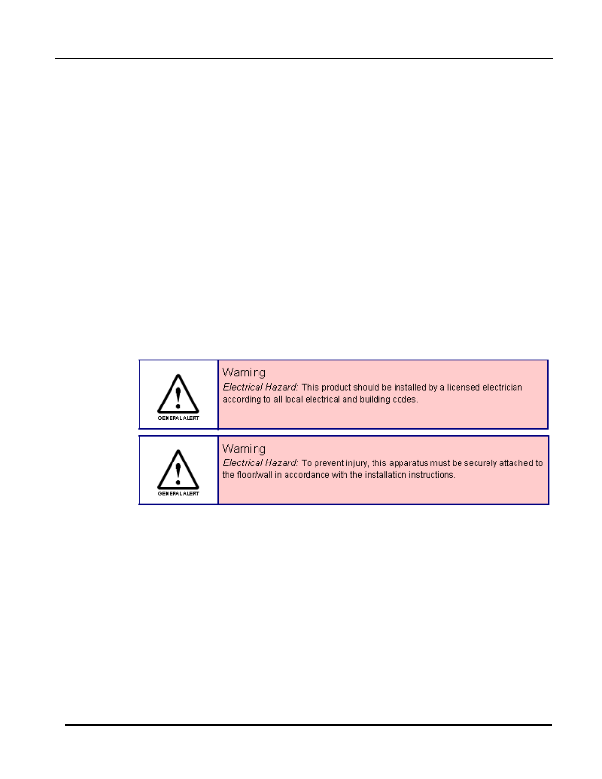
14. Warning
This device may be opened and reassembled by qualified personnel only, for the purposes of
installing the product, making adjustments and replacing components, following the instructions in
the product manual.
High voltages may be present in this product when connected to telephone wiring.
15. Service Telephone Number
1-800-363-8010
Guardian Telecom provides a customer service telephone number which is toll-free within North
America. If you need assistance when installing or operating this product, please call the toll-free
telephone number between regular business hours (8:00AM-5:00PM), Mountain Standard Time. If
you are calling outside of regular business hours, please leave a detailed message, and a member
of Guardian Telecom’s Service Department will return your call as soon as possible. If your product
requires service, Guardian personnel will supply you with an RMA (return materials authorization)
number over the telephone or through our web site product return page. This number must be
included with your return address and the name of the person to contact.
Guardian Telecom, a division of Circa Enterprises Inc.
Toll-free 1-800-363-8010
Phone (403) 258-3100
Fax. (403) 253-4967
www.guardiantelecom.com
16. Feedback
Guardian Telecom continually strives to make reliable, durable, and easy to use products. If you, as
an installer or user of our equipment, have any suggestions for improvements to this or any of our
products or documents, including this manual, we would appreciate hearing from you.

Guardian Telecom Inc. Installation and Operation
ACR/ACT-VoIP Series Telephones
Page 20
17. Guardian Product Return
Guardian products have been quality tested and are in full working order when
shipped from the factory, given the rugged nature of these products shipping is not
expected to damage a unit. In the unlikely event of a malfunction Guardian follows the
three step procedure below.
Step I - On-Site Correction
The most common source of difficulties with a new product is improper installation in
one of two ways: incorrect wiring connections or connection to an incorrect power
source.
Product wiring needs to be properly connected to the on-site wiring. Correct wiring
instructions are shown in the user manuals included with the product.
When a product has been installed following user manual instructions, and the unit
fails to operate, the user must contact Guardian Telecom to obtain authorization to
return the product. This can be done by completing an RMA form online at
https://www.guardiantelecom.com/support/rma/, or by calling the service telephone
number given in this manual.
Step II - Return Materials Authorization (RMA)
When a product has been installed following user manual instructions, and the unit
fails to operate, the user must contact Guardian Telecom to obtain authorization to
return the product. This can be done by done by completing a RMA form online at
www.guardiantelecom.com, or by calling the service telephone number given in this
manual.
After providing information on the product, the owner and the nature of the problem,
Guardian will issue a RMA number, to be shown on documentation returned with the
product.
In addition to the RMA number, shipping documents should include name, address
and telephone number of the owner along with contact information for the person
responsible for the repair and/or the user who identified the malfunction.
(Where a product is being returned for repair from outside of Canada, customs
documentation must show the product’s serial number, date of export [date of
purchase], and a notation that the equipment is: “Canadian goods returning.”)
Step III - Factory Authorized Service
Once received, each product is carefully inspected and tested. If the product is under
warranty, repairs are completed and the product returned to the owner, generally
within five working days of receipt by the factory.
A product that has been subjected to misuse, neglect or accident or is beyond the
warranty period will be evaluated. The service department will provide the owner’s
representative with a repair cost estimate. Once approved, repairs are completed and
the product returned, generally within five working days.
This manual suits for next models
3
Table of contents
Other Circa Enterprises Inc. IP Phone manuals


