Circa Enterprises Inc. Guardian HDE Series Quick guide
VoIP Telephones
HDE Setup & Configuration
APPLICABLE FOR FIRMWARE VERSION V3.9.0 OR LATER
P007451 Rev. I 20100710 7/10/2020 11:22 AM

Setup & Configuration
HDE-VoIP Telephones
Page 2
VoIP Setup & Configuration P007451 Rev. I(applicable to firmware V3.9.0 Only!)
COPYRIGHT NOTICE:
© 2020, Guardian Telecom, ALL RIGHTS RESERVED.
This manual and related material is the copyrighted property of Guardian Telecom. No part of this manual or related materials
may be reproduced or transmitted, in any form or by any means (except for internal use by licensed customers), without prior
express written permission of Guardian Telecom. This manual, and the products, software, firmware, and/or hardware
described in this manual are the property of Guardian Telecom provided under the terms of an agreement between Guardian
Telecom and the recipient of this manual, and their use is subject to that agreement and its terms.
DISCLAIMER: Except as expressly and specifically stated in a written agreement executed by Guardian Telecom, Guardian
Telecom makes no representation or warranty, express or implied, including any warranty or merchantability or fitness for any
purpose, with respect to this manual or the products, software, firmware, and/or hardware described herein. Guardian Telecom
assumes no liability for damages or claims resulting from any use of this manual or such products, software, firmware, and/or
hardware. Guardian Telecom reserves the right to make changes, without notice, to this manual and to any such product,
software, firmware, and/or hardware.
OPEN SOURCE STATEMENT: Certain software components included in Guardian products are subject to the GNU General
Public License (GPL) and Lesser GNU General Public License (LGPL) “open source” or “free software” licenses. Some of this
Open Source Software may be owned by third parties. Open Source Software is not subject to the terms and conditions of the
Guardian COPYRIGHT NOTICE or software licenses. Your right to copy, modify, and distribute any Open Source Software is
determined by the terms of the GPL, LGPL, or third party, according to who licenses that software.
Software or firmware provided by Guardian that is unrelated to Open Source Software is copyrighted by Guardian, subject to
the terms of Guardian licenses, and may not be copied, modified, reverse-engineered, or otherwise altered without explicit
written permission from Guardian Telecom.
TRADEMARK NOTICE: Guardian Telecom and the Guardian Telecom logos are trademarks of Guardian Telecom Other
product names, trademarks, and service marks may be the trademarks or registered trademarks of their respective owners.
Toll-free 1-800-363-8010
Phone (403) 258-3100
Fax. (403) 255-2595
www.guardiantelecom.com
E-mail: [email protected]

Setup & Configuration
HDE-VoIP Telephones
Page 3
Updating Your VoIP Product
Please review www.guardiantelecom.com support pages to obtain the latest F/W or contact Guardian Telecom
Support at mailto:rmateststation@guardiantelecom.com
Important Safety Instructions
1. Read these instructions.
2. Keep these instructions.
3. Heed all warnings.
4. Follow all instructions.
5. Install in accordance with the manufacturer’s instructions.
6. Do not install near any heat sources such as radiators, heat registers, stoves, or other apparatus
(including amplifiers) that produce heat.
7. Only use attachments/accessories specified by the manufacturer.
8. Refer all servicing to qualified service personnel.
9. Prior to installation, consult local building and electrical code requirements.

Setup & Configuration
HDE-VoIP Telephones
Page 4
Table of Contents
1. Typical System Installation......................................................................................... 6
2. Supported Protocols................................................................................................... 6
3. Supported SIP Servers............................................................................................... 6
4. Features ..................................................................................................................... 7
5. Getting Started ........................................................................................................... 8
6. Back-Up Server Modes .............................................................................................. 8
6.1. Normal Operation (SRST/MITEL) Disabled .................................................... 8
6.2. Cisco SRST .................................................................................................... 8
6.3. Mitel Resiliency............................................................................................... 9
7. RESET Switch.......................................................................................................... 10
8. Configure the Telephone Parameters ...................................................................... 10
8.1. Telephone Web Page Navigation ................................................................. 10
8.2. Log in to the Configuration Home Page........................................................ 11
8.3. Configure the Device Parameters................................................................. 13
8.4. Configure the SIP Parameters ...................................................................... 18
8.5. Configure the Audio Parameters................................................................... 23
8.5.1. User-created Audio Files ...................................................................... 25
8.6. Configure the Event Parameters................................................................... 27
8.7. Configure the Autoprovisioning Parameters.................................................. 31
8.8. Configure Update Firmware.......................................................................... 33
8.8.1. Reboot the Telephone.......................................................................... 33
9. Setting up a TFTP Server......................................................................................... 34
9.1. In a LINUX Environment ............................................................................... 34
9.2. In a Windows Environment ........................................................................... 34
10. Operation.................................................................................................................. 35
11. Frequently Asked Questions .................................................................................... 36
12. Product Specifications.............................................................................................. 38
13. Appendix A Time Zone Settings ............................................................................... 39
Figures
Figure 1 - Typical Installation .............................................................................................. 6
Figure 2 - Startup Screen.................................................................................................... 8
Figure 3 - Home Page....................................................................................................... 11
Figure 4 - Device Configuration Page ............................................................................... 13
Figure 5 - Network Configuration Page............................................................................. 16
Figure 6 - SIP Configuration Page .................................................................................... 18
Figure 7 - Audio Configuration Page................................................................................. 23
Figure 8 - Audacity 1......................................................................................................... 25
Figure 9 - Audacity 2......................................................................................................... 25
Figure 10 - WAV (Microsoft) signed 16 bit PCM ............................................................... 26
Figure 11 - Event Configuration Page............................................................................... 27
Figure 12 - Autoprovisioning Configuration Page.............................................................. 31
Figure 13 - Update Firmware Page................................................................................... 33

Setup & Configuration
HDE-VoIP Telephones
Page 5
Tables
Table 1 - Factory Default Settings.....................................................................................10
Table 2 - Telephone Web Page Navigation.......................................................................10
Table 3 - Home Page Overview ........................................................................................12
Table 4 - Device Configuration Parameters ......................................................................15
Table 5 - Network Configuration Parameters ....................................................................17
Table 6 - SIP Configuration Parameters............................................................................22
Table 7 - Audio Configuration Parameters ........................................................................24
Table 8 - Event Configuration............................................................................................30
Table 9 - Autoprovisioning Configuration Parameters.......................................................32
Table 10 - Firmware Update Parameters ..........................................................................33
Acronyms
DHCP Server
Dynamic Host Configuration Protocol
DHCPD
Dynamic Host Configuration Protocol Daemon
DTMF
Dual-tone Multi-frequency
HTTP
Hypertext Transfer Protocol
IP Address
Internet Protocol Address
LAN
Local Area Network
LINUX
Unix-like computer operating system
PBX
Private Branch Exchange
PC
Personal Computer
PCM
Pulse-Code Modulation
PCMA
Paired Carrier Multiple Access
PCMU
Pulse Code Modulation mu-law
PoE
Power over Ethernet
POST
Power On Self-Test
RIFF
A short, repeated musical phrase
RTP
Real-time Transport Protocol
RTP Port
Real-time Transport Protocol port
AVP
Audio Video Profile
SIP
Session Initiation Protocol
TFTP
Trivial File Transfer Protocol
URL
Uniform Resource Locator
VoIP
Voice Over Internet Protocol
WAV
Waveform Audio File Format
WAVE
Waveform Audio File Format
XML File
Extensible Markup Language

Setup & Configuration
HDE-VoIP Telephones
Page 6
1. Typical System Installation
The Voice-over-IP (VoIP) Telephone is a Power-over-Ethernet (PoE 802.3af) and Voice-over-IP (VoIP) two-way
communications device that easily connects into existing local area networks (LANs) with a single cable connection. The
telephone is compatible with all SIP Compliant hardware or cloud based servers.
Figure 1 illustrates how VoIP Telephones can be installed as part of a VoIP phone system.
Figure 1 - Typical Installation
2. Supported Protocols
The VoIP Telephone with Keypad supports:
●SIP (Session Initiation Protocol)
●HTTP Web-based configuration
Provides an intuitive user interface for easy system configuration and verification of a VoIP Telephone.
●DHCP Client
Dynamically assigns IP addresses in addition to the option to use static addressing.
●TFTP Client
Facilitates hosting for the Autoprovisioning configuration file.
●RTP
Facilitates autoprovisioning configuration values on boot
●Audio Encodings
PCMU (G.711 mu-law)
PCMA (G.711 A-law)
G.722.1 (SIREN 7)
G.722.2 (ANR-WB)
g.729 (729J & 729EV)
3. Supported SIP Servers
As a SIP device, this product will operate with all SIP Compliant hardware or cloud based servers. Contact Guardian
Sales or Support on any interoperability questions. A list of formally tested compliant servers is available on the
Guardian Website.

Setup & Configuration
HDE-VoIP Telephones
Page 7
4. Features
Standard Features on All Models
•PoE 802.3af enabled (Power-over-Ethernet) or alternate power source.
•Control Relay – network configurable auxiliary relay.
•Compatible with SIP-based IP-PBX servers that comply with SIP RFC 3261.
•Network web management.
•Device Configuration Manager allows a significant operational list of features concerning the Auxiliary relay, LED
functions, Audio setup and others.
•Guardian Discovery Utility makes it easy to detect, locate and launch the web based configuration screens.
•Product self-diagnostic testing available through web interface.
•Network adjustable volume and microphone sensitivity.
•Network downloadable firmware.
•Remote programming provides network management from a central location.
•Night ringer mode.
Single Button Units:
•Calls may be initiated from the phone or answered from the monitoring station.
•Can be used for Emergency or Information type applications.
•Single Push Button – depressing once automatically rings designated number to summon help. Use the Red Button
Register in the SIP configuration to store the auto-dialed number.
•Integrated LED – provides visual confirmation of call status and connection or can be configured alternatively through
the Device Configuration.
•Doubles as a Paging Speaker when Auto-Answer is enabled.
•Auxiliary Relay can be programmed using several modes as required (Note: Power limits).
•Night ringer mode available.
Dual Button Units with / without Telephone keypad:
•Calls may be initiated from the phone or answered from the monitoring station.
•Can be used for Emergency AND Information type applications with a single unit.
•Separate button to designate for emergency and one for Information or to activate keypad (if equipped).
•Emergency Push Button – depressing once automatically rings designated number to summon help. Use the Red
Button Register in the SIP configuration to store the auto-dialed number.
•Information Button – Depressing once to call an information operator. Use Blue button register in the SIP
configuration to store this number.
•Keypad – If installed, leave Blue button register BLANK. Then if pushed, a dial tone will be heard and user can direct
dial via the keypad.
•Integrated LED’s (Qty. 2) – provides visual confirmation of call status and connection or can be configured
alternatively through the Device Configuration.
•Doubles as a Paging Speaker when Auto-Answer is enabled.
•Auxiliary Relay can be programmed using several modes as required (Note: Power limits).
•Night ringer mode available.
Setup & Configuration
HDE-VoIP Telephones
Page 8
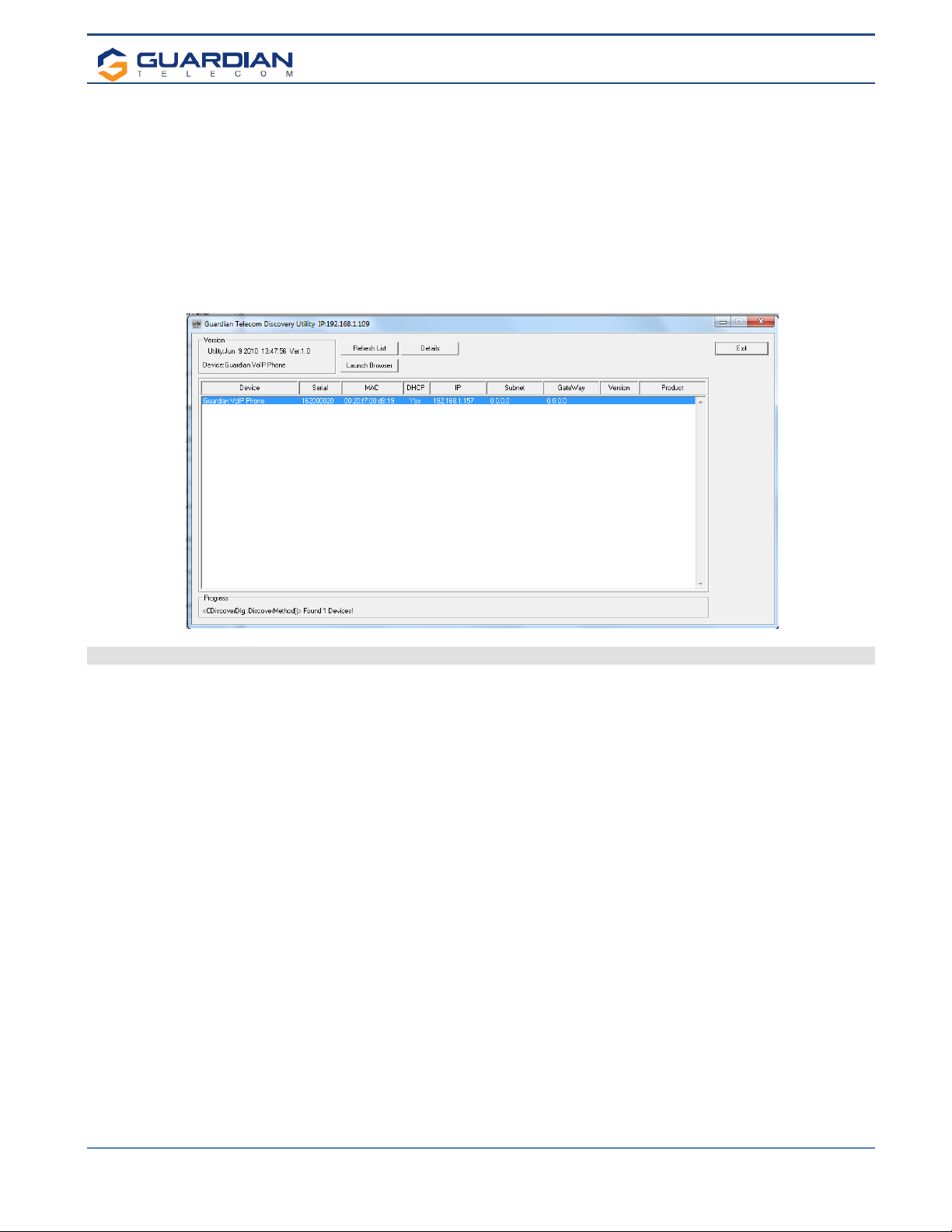
5. Getting Started
The Installation manual for the telephone provides information on installing and connecting the device to the server.
This manual describes the steps required to customize the telephone to suit the individual’s preferences.
The Discovery Utility is available on Guardian’s website at https://www.guardiantelecom.com/resources/voip-support/ and
needs to be installed manually by copying the executable file to a local drive.
To access a VoIP phone for programming:
•Copy the Guardian Discovery Utility onto the network server or SIP server.
•Start the Utility by double clicking the icon.
•Click on “Refresh List”.
•Click on the device to be programmed to highlight it.
•Click on “Launch Browser”.
Figure 2 - Startup Screen
6. Back-Up Server Modes
6.1. Normal Operation (SRST/MITEL) Disabled
Guardian Normal Backup Process:
If the primary server fails, the phone will attempt to register automatically with backup #2, if that fails, it will try with
backup #3. It will cycle through the servers until it registers or it will remain unregistered (if all servers off-
line). Once the phone establishes a link to the back up, it will remain on that server until a forced reset occurs or
the server it is on, kicks it out (reset or unregistration). Then the phone will re-attempt registration starting with the
primary server.
For all the above at anytime for any of the above, occurs and phone is not registered within 60 seconds of drop and
if the event mode is enabled for heartbeat, the phone will issue out a XML notification.
6.2. Cisco SRST
Cisco Unified SRST functions in the remote-location router to automatically detect a failure in the network and
initiate a process to provide call-processing backup redundancy for the IP phones in that location and help ensure
that the telephony capabilities stay operational. Upon restoration of WAN connectivity, the system intelligently and
automatically shifts call processing back to the primary Cisco Unified Communications Manager cluster.

Setup & Configuration
HDE-VoIP Telephones
Page 9
6.3. Mitel Resiliency
The Mitel Resiliency filter allows for seamless failover between two Mitel SIP servers without user intervention.
The device supports two levels of resiliency: Bronze and Silver.
Bronze:
The device supports multiple DNS records for a single FQDN. If the device fails to register with one server via an IP
address associated with the FQDN’s DNS record, it will try other IP addresses given. Alternatively, the DNS server
can provide a single IP address for an FQDN if it is aware of the servers’ statuses.
Silver:
While idle, the device will attempt to register with the primary Mitel SIP server (“Primary SIP Server” in the device’s
configuration). If the device fails to register with this primary server at any point, it will register with the secondary
Mitel SIP server (“Backup SIP Server 1” in the device’s configuration). The device will maintain registration with the
secondary server, but will indefinitely attempt to re-register with the primary server. When the primary server comes
back online, the device will unregister with the secondary server and go back to registering with the primary server.
On first boot (or first registration), the time it takes for the device to failover to the secondary server is based on
timers in the SIP RFC. Once the device has successfully registered with a (any) server, the time it takes for the
device to failover to another server is based on the same timers as well as the SIP Re-registration Interval
specified in the device’s configuration. The device attempts to re-register with its SIP server at about 66% of the
specified interval, which should result in downtime of no more than 75% of the specified interval.
When the device sends a SIP INVITE request, the device will start a timer (“Invite Timeout” in the device’s
configuration). If the SIP INVITE exchange is not successfully completed before this timer expires, the call will be
aborted and the device will failover to the next server. The user will need to attempt the call again.
Setup & Configuration
HDE-VoIP Telephones
Page 10
7. RESET Switch
• The RESET switch is used to get the IP address of the device or reset to factory defaults.
• Press and release the RESET switch within a 5 second window and it will speak the IP address through the on
board speaker.
• Press and hold the RESET switch for more than10 seconds until it indicates that it is restoring defaults and
rebooting the board.
8. Configure the Telephone Parameters
To configure the Telephone online use a standard web browser.
All Telephones are initially configured with the following default IP settings:
Parameter Factory Default Setting
IP Addressing DHCP
IP Addressa
10.10.10.10
Web Access Username admin
Web Access Password admin
Subnet Maska255.0.0.0
Default Gatewaya10.0.0.1
Table 1 - Factory Default Settings
a. Default if there is not a DHCP server present.
When configuring more than one Telephone attach the Telephones to the network and configure one at a time to avoid IP
address conflicts.
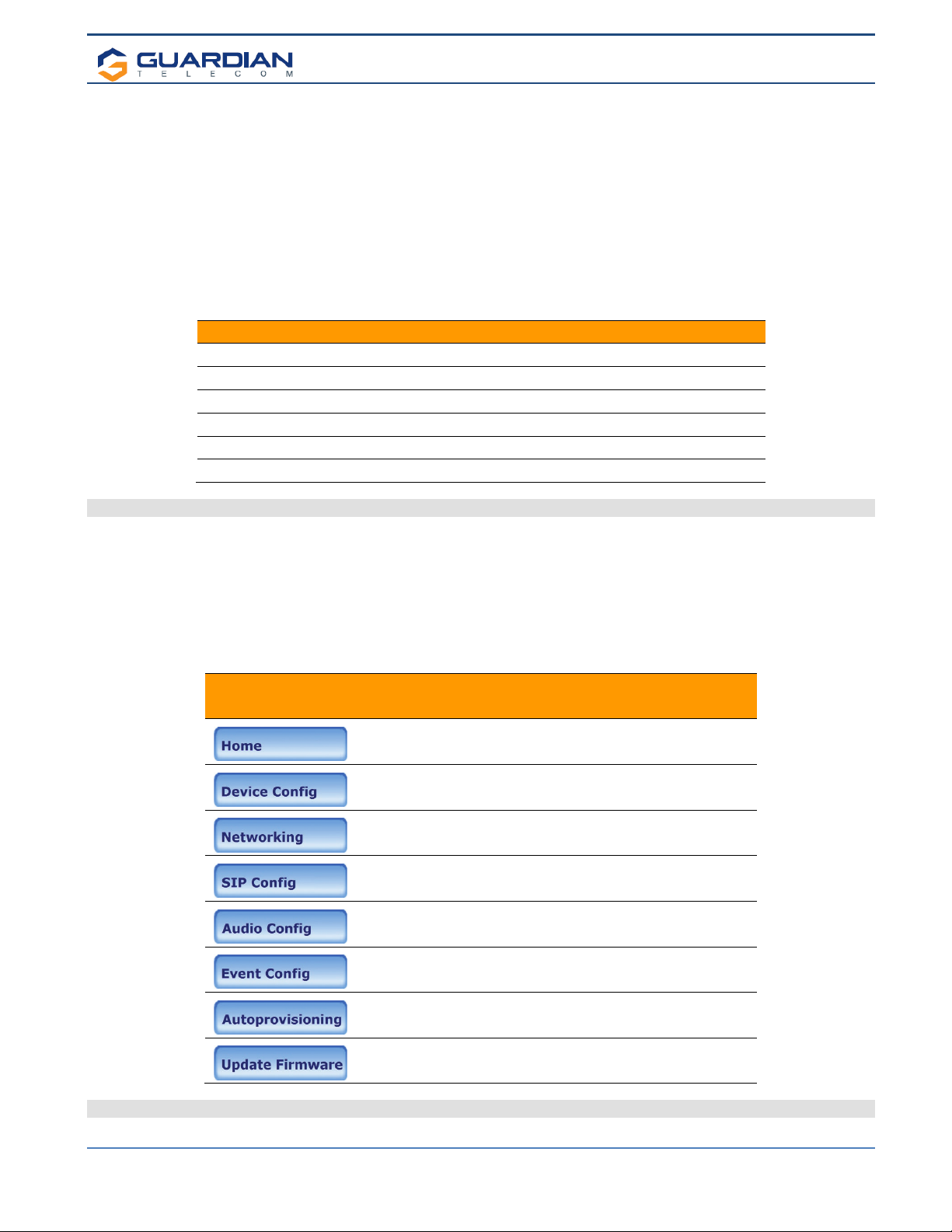
8.1. Telephone Web Page Navigation
Table 2 shows the navigation buttons that will be seen on every Telephone web page.
Web Page Item Description
Link to the Home page.
Link to the Device Configuration page.
Link to the Networking page.
Link to the SIP Configuration page.
Link to the Audio Configuration page.
Link to the Event Configuration page.
Link to the Autoprovisioning Configuration page.
Link to the Update Firmware page.
Table 2 - Telephone Web Page Navigation

Setup & Configuration
HDE-VoIP Telephones
Page 11
8.2. Log in to the Configuration Home Page
1. Open your browser to the Telephone’s IP address. If you do not know the IP address, the “Discovery Utility” can be
used to detect all Guardian VoIP devices on the network. When opened refresh the Discovery Utility list to trigger the
application to scan the network for VoIP devices.Individually select the device and launch the browser. Another method to
obtain the IP address is to press the RESET switch for approximately one to five seconds, then release. The phone will
announce the address through the speaker. The physical location of a telephone can be determined by comparing the
MAC Address, IP Address or Serial Number shown on the Discovery Utility screen with the information on the unit.
Note:If the network does not have access to a DHCP server, the device will default to an IP address of
10.10.10.10.
Note:Make sure that the PC is on the same IP network as the Telephone.
2. When prompted, use the following default Web Access Username and Web Access Password to access the Home
Page (Figure 3):
Web Access Username: admin
Web Access Password: admin (Iower case)
3. On the Home Page, review the setup details and navigation buttons described inTable 3.
Note: The Screen Captures shown are only examples; refer to the tables for definitions.
Figure 3 - Home Page
Setup & Configuration
HDE-VoIP Telephones
Page 12
Web Page Item Description
Device Settings
Device Name: Change the device name as required.
Change Username: Type in this field to change the username.
Change Password: Type in this field to change the password.
Re-enter Password: Type the password again in this field to confirm the new password.
Current Settings
Serial Number: Shows the device serial number.
Mac Address: Shows the device MAC address.
Firmware Version: Shows the current firmware version.
IP Addressing: Shows the current IP addressing setting (DHCP or static).
IP Address: Shows the current IP address.
Subnet Mask: Shows the current subnet mask address.
Default Gateway: Shows the current default gateway address.
DNS Server 1: Shows the current DNS Server 1 address.
DNS Server 2: Shows the current DNS Server 2 address.
Speaker Volume: Shows the current speaker volume level.
Microphone Gain: Shows the current microphone gain level.
SIP Mode is: Shows the current SIP Mode status.
Event Reporting is: Shows the current Event Reporting status.
Nightringer is: Ringtone broadcast when enabled and extension is called.
Primary SIP Server: Primary SIP Server
Backup Server 1: Redundant SIP Server “1”
Backup Server 2: Redundant SIP Server “2”
LED1 / LED2 State: This will indicate if LED is “Active” (on) or “Inactive” (off) – Useful when using
toggle Mode (i.e.: DTMF enabled with timer set to “0” Zero seconds).
Import/Export Settings
Choose File Select a configuration file to import to the device.
Import Configuration
Click to import the selected configuration file. The configuration file allows the
user to set up a custom default configuration for the VoIP products and import
into multiple devices to save time.
Export Configuration
Click to export the current configuration to a file. The export file can then be
used to confirm, share or modify and re-import back into the VoIP devices.
Click the Save button to save the configuration settings.
Note: You need to reboot for changes to take effect.
Click on the Reboot button to reboot the device.
Table 3 - Home Page Overview

Setup & Configuration
HDE-VoIP Telephones
Page 13
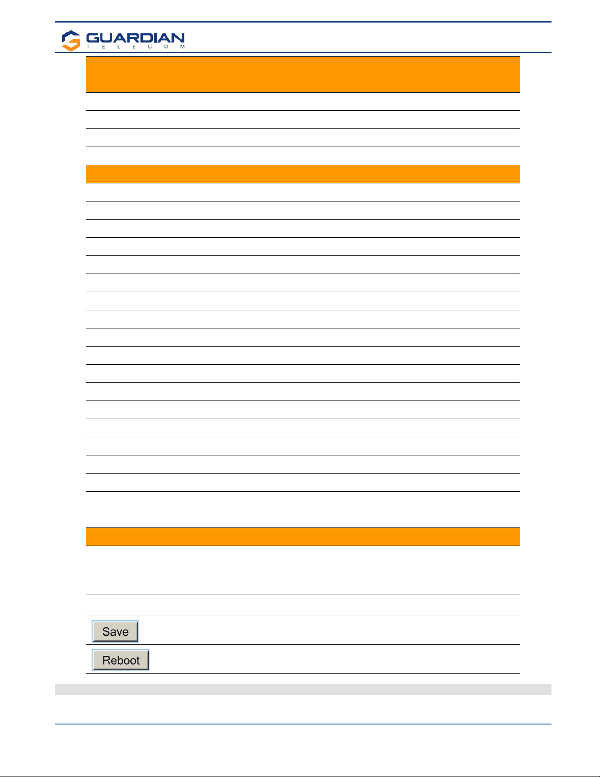
8.3. Configure the Device Parameters
1. Click the Device Configuration button to open the Device Configuration page. See Figure 4.
Figure 4 - Device Configuration Page
2. On the Device Configuration page, you may enter values for the parameters indicated in Table 4.
3. After changing the parameters, click the Save button followed by Reboot to complete.
Setup & Configuration
HDE-VoIP Telephones
Page 14
Web Page Item Description
Volume Settings
The volume settings describe the volume set on reboot. The user can change the
volume by using the up and down arrows, but this change is temporary and the
volume will be reset when the device is rebooted.
Speaker Volume (0-9):
The speaker volume sets the default volume of the device on boot. Valid values are 0-
9. Test the speaker volume using the ‘Test Audio’ button below.
HL Gain Control (0-9) This is used in conjunction with the optional VoIP Extender Module w/Hearing Aid
Loop amplifier. Only for units which are equipped with a Hearing Aid T-Coil Antenna.
Microphone Gain (0-9):
The microphone gain sets the initial input gain of the on board microphone. Valid
values are 0-9. Test the speaker volume using the ‘Test Microphone’ button below.
Ringer Volume (0-9):
The ringing volume that is heard on the speaker of the phone. Valid values are 0-9.
This setting is for units that use the speaker as a ringer. It will not affect units with a
fixed buzzer.
Aux Port
Activate Relay with DTMF Code: When this option is enabled, the device will activate the relay when it receives a DTMF
code (SIP or rfc2833).
DTMF Activation Code:
This 25-character field (Digits 0-9 only) can be used to set a DTMF code used to
activate the relay. NOTE: the operator must press the “#” or “✱” key after entering the
code for it to be accepted.
DTMF Activation Duration (in
seconds):
When the relay is activated with a DTMF code, it will remain active for this duration in
seconds. Valid values are 1-9.
NOTE: A DTMF activation of 0will toggle the relay indefinitely or until the activation,
code is sent again.
Activate Relay During Ring:
When this option is enabled, the relay will activate when the device has received a call
and is playing a ringtone.
Activate Relay During Night Ring:
When this option is enabled, the relay will activate when the device has received a call
to the night ring extension.
Pulse Relay when Ringing:
On in-coming calls…When a “ring” is present the relay will pulse with a cadence of 2
seconds on, 3 seconds off.
Pulse Buzzer when Ringing:
When a “ring” is present the internal ringer will pulse with a cadence of 2 seconds on,
3 seconds off.
Activate Relay on Outgoing Ring
When enabled, once a push button is pressed, the relay will activate and remain
activated until the call is answered. Then it will deactivate unless the “Activate Relay
While Call Active” is also enabled.
Activate Relay While Call Active:
When this option is enabled, the relay will activate when a call is established with
another SIP device. It will remain active for the duration of the call.
Expansion Module Enable
Check this feature when used with the Guardian Telecom VoIP Expansion Module.
This activates the extended relay management features.
LED1 & LED 2 Control Setup (LED1 shown, LED2 similar)
Activate LED1 with DTMF Code:
When this option is enabled, the device will activate Output Port 1 (Generally wired to
the Emergency Button respective LED) when it receives a DTMF code (SIP or
rfc2833).
Activate LED2 with DTMF Code:
When this option is enabled, the device will activate Output Port 2 (Generally wired to
the Information or General Call Button respective LED) when it receives a DTMF code
(SIP or rfc2833).
DTMF Activation Code:
This 25-character field (Digits 0-9 only) can be used to set a DTMF code used to
activate the LED.
NOTE: the operator must press the “#” or “✱”key after entering the code for it to be
accepted.
DTMF Activation Duration (in
seconds):
When the LED is activated with a DTMF code, it will remain active for this duration in
seconds. Valid values are 1-9.
NOTE: A DTMF activation of 0will toggle the LED state indefinitely until the activation
code is sent again.
Blink LEDn on Call, Solid while Call
Active:
Active button – LED will flash on/off during call progress and remain on once call link is
established.
Solid LEDn, Blink during ring & call LED always on, blinks when button pressed and for duration of call.
Setup & Configuration
HDE-VoIP Telephones
Page 15
Blink LEDn During Ring: LED for respective button will flash on receipt of call during device ringing.
Blink LEDn During Night Ring When this option is enabled, the LED will activate and flash when the device has
received a call and is playing a ringtone.
Solid LEDn During Ring: LED activated during receipt of call and in ring mode.
Solid LEDn During Night Ring: LED activated during receipt of call and in night ring mode.
NTP Settings
NTP Server
Use this field to set the address (in IPv4 dotted decimal notation or as a canonical
name) for the NTP Server. This field can accept canonical names of up to 64
characters in length.
Posix Timezone String
Allows the device to access a local network based time server or a global internet
server to allow the device to auto set/update the device clock. See Appendix A.
Set Time with external NTP server
on Boot
When selected, the time is set with an external the NTP server when the device
restarts.
Periodically update with time server
When selected, the time is periodically updated with the NTP server at the configured
interval below.
Time update period (in hours)
The time interval after which the device will contact the NTP server to update the time.
Enter up to 4 digits.
Set time from NTP Server Clicking on this button will immediately set the time.
Current Time
Current Time in 24 hour format
(HHMMSS):
Allows you to input the current time manually. (6 character limit)
Current Date (MMDDYY): Allows you to input the current date manually. (6 character limit)
Set Clock Clicking on this button will immediately set the clock format.
Miscellaneous Settings
Disable HTTPS (NOT
recommended):
Disables the encrypted connection to the webpage. Depending on network security
enable / disable as required.
Call Termination Lockout*:
When this option is enabled, a call cannot be terminated using the Emergency Call
button.
Auto-Answer Incoming Calls
When selected, the device will automatically answer incoming calls. When Auto-
Answer Incoming Calls is disabled, the device will play a ring tone (corresponds to
Ring Tone on the Audiofiles page) out of the speaker, or the buzzer will sound until
someone presses the Call button to answer the call or the caller disconnects before
the call can be answered.
DTMF Termination Key Key can be * or # as user chooses.
This button will play an audio test message and can be used to test the volume level.
When this button is pressed the device will record 3 seconds of audio, beep, and then
play back the recorded audio. This can be used to test the microphone gain level.
This button will activate the relay for the DTMF activation Duration (in seconds).
When this button is toggled, it will put the device into button test mode. In this mode,
the speaker will play an audio file when a button is pressed on the device. For normal
keypad input (keys 0-9), it will speak the associated file from the audio configuration
page. For the other keypad keys, (*, #, any other function keys) it will play a DTMF
tone while the button is depressed. The button press mode will time out after 60
seconds.
Click the Save button to save your configuration settings.
Note
: You need to reboot for changes to take effect.
Click on the Reboot button to reboot the device.
•You need to reboot for changes to take effect
•*Call termination lock out only applies to red button calls
Click on this to run the new advanced diagnostics manually.
Table 4 - Device Configuration Parameters
Setup & Configuration
HDE-VoIP Telephones
Page 16
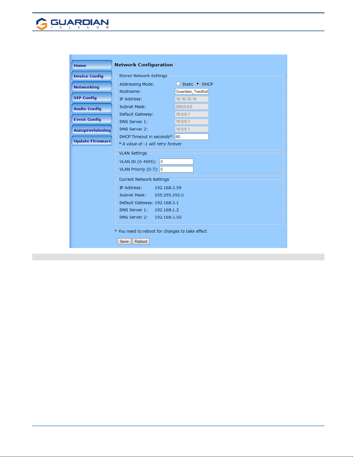
Configure the Network Parameters
1. Click the Networking button to open the Network Configuration page (Figure 5).
Figure 5 - Network Configuration Page
2. On the Network Configuration page, enter values for the parameters indicated in Table 5.
3. After changing the parameters, click Save to store the settings before going to the other configuration pages. If no other
changes are required beyond this state, click Reboot to reset the device for other changes to take effect.
The new settings will not take effect if Reboot is clicked without saving first.
4. Connect the Telephone to the target network.
5. From a computer on the same network as the Telephone, open a browser with the new IP address of the Telephone.
Note: If changing from DHCP to STATIC Only: Once the reboot button has been selected, the webpage will show a
countdown timer. The timer will hit zero and will reset and continue with countdown. At this point the web page can be
shutdown and re-started. The web page will not automatically restart when switching from DHCP to STATIC.
Setup & Configuration
HDE-VoIP Telephones
Page 17
Web Page Item Description
Stored Network Settings Shows the settings stored in non-volatile memory.
Addressing Mode:
Select either DHCP IP Addressing or Static Addressing by marking the
appropriate radio button. DHCP Addressing mode is enabled on default and the
device will attempt to resolve network addressing with the local DHCP server
upon boot. If DHCP Addressing fails, the device will revert to the last known IP
address or the factory default address if no prior DHCP lease was established.
See Table 1 for factory default settings. Be sure to click Save and Reboot to
store changes when configuring a Static address.
Hostname: This is the hostname provided by the DHCP server. See the DHCP/DNS server
documentation for more information. Enter up to 64 characters.
IP Address: The IPv4 static IP address in standard dotted decimal notation.
Subnet Mask: The IPv4 routing prefix in standard dotted decimal notation.
Default Gateway: This is the node to go to when an IP address does not match any routes in the
routing table. This requires standard quad-dotted decimal notation.
DNS Server 1:
DNS Server 2:
The DNS server configuration is used to setup the primary and secondary name
servers for the network. These use standard dotted decimal notation.
DHCP Timeout in seconds*:
*A value of –1 will retry
forever
Specify the desired time-out duration (in seconds) that the device will wait for a
response from the DHCP server before reverting back to the stored static IP
address. The stored static IP address may be the last known IP address or the
factory default address if no prior DHCP lease was established. Enter up to 8
characters. A value of -1 will retry forever.
VLAN Settings Shows the current VLAN settings.
VLAN ID (0-4095):
Specify the IEEE 802.1Q VLAN ID number. Enter up to 4 digits. Note: The
device supports 802.1Q VLAN tagging support. The switch port connected to
the device will need to be in “trunking mode” for the VLAN tags to propagate.
VLAN Priority (0-7): Specify the IEEE 802.1p VLAN priority level. Enter 1 digit. A value of 0 may
cause the VLAN ID tag to be ignored.
Current Network Settings Shows the current network settings.
IP Address: Shows the current Static IP address.
Subnet Mask: Shows the current Subnet Mask address.
Default Gateway: Shows the current Default Gateway address.
DNS Server 1: Shows the current DNS Server 1 address.
DNS Server 2: Shows the current DNS Server 2 address.
Click the Save button to save your configuration settings.
Note: You need to reboot for changes to take effect.
Click on the Reboot button to reboot the device.
•You need to reboot for changes to take effect
Table 5 - Network Configuration Parameters
Setup & Configuration
HDE-VoIP Telephones
Page 18
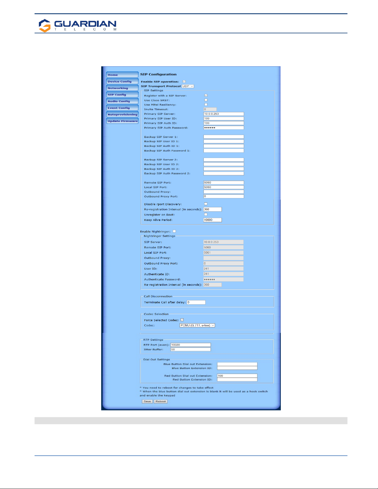
8.4. Configure the SIP Parameters
1. Click SIP Config to open the SIP Configuration page (Figure 6).
Note:Guardian VoIP telephones are compatible with most SIP servers.
Figure 6 - SIP Configuration Page
2. On the SIP Configuration page, enter values for the parameters indicated in Table 6.
3. After changing the parameters, click Save Settings

Setup & Configuration
HDE-VoIP Telephones
Page 19
Web Page Item Description
Enable SIP Operation:
When this option is enabled, the device will initialize the SIP engine
and try to register with a SIP server or listen for incoming SIP
connections.
SIP Transport Protocol Allows user to select between SIP TCP or UDP mode.
SIP Settings
Register with a SIP Server:
When enabled, the device will attempt to register to the configured
SIP Server(s) on this page. To configure the device to send and
receive point-to-point SIP calls, enable SIP Operation and disable
Register with a SIP Server.
Use Cisco SRST:
When enabled, the backup servers are handled according to Cisco
SRST (Survivable Remote Site Telephony). It is required for use in
clustered Cisco Unified Communications Manager topologies.
Use Mitel Resiliency: When used with MITEL PBX with Mitel proprietary redundancy, this
enables compliance operating mode for compatibility.
Invite Timeout:
When Mitel Resiliency is enabled, the device will use the “Invite
timeout” value for outbound calls. The device will send an invite and
if it does not get a response from the SIP server in <value>
seconds, it will presume the server is down, cancel the call, and
failover to the next server.
Primary SIP Server:
Enter the SIP server address as an IPv4 address in dotted decimal
notation or a fully qualified domain name. This parameter also
becomes the host portion of the SIP-URI for the device's extension
on the primary SIP server. This field can accept entries of up to 255
characters in length.
Primary SIP User ID:
Specify the SIP User ID for the Primary SIP Server. This parameter
becomes the user portion of the SIP-URI for the device's extension
on the primary SIP server. Enter up to 64 alphanumeric characters.
Primary SIP Auth ID:
Specify the Authenticate ID for the Primary SIP Server. This
parameter is required for SIP registration authentication. Enter up to
64 alphanumeric characters.
Primary SIP Auth Password:
Specify the Authenticate Password for the Primary SIP Server. This
parameter is required for SIP registration authentication. Enter up to
64 alphanumeric characters.
Backup SIP Server 1:
Enter the backup SIP server address as an IPv4 address in dotted
decimal notation or a fully qualified domain name. This parameter
also becomes the host portion of the SIP-URI for the device's
extension on the backup SIP server. This field can accept entries of
up to 255 characters in length.
Backup SIP User ID 1:
Specify the SIP User ID for the first backup SIP Server. This
parameter becomes the user portion of the SIP-URI for the device's
extension on the first backup SIP server. Enter up to 64
alphanumeric characters.
Backup SIP Auth ID 1:
Specify the Authenticate ID for the first backup SIP server. This
parameter is required for SIP registration authentication. Enter up to
64 alphanumeric characters.
Backup SIP Auth Password 1:
Specify the Authenticate Password for the first backup SIP server.
This parameter is required for SIP registration authentication. Enter
up to 64 alphanumeric characters.

Setup & Configuration
HDE-VoIP Telephones
Page 20
Backup SIP Server 2:
Enter a second backup SIP server address as an IPv4 address in
dotted decimal notation or a fully qualified domain name. This
parameter also becomes the host portion of the SIP-URI for the
device's extension on the second backup SIP server. This field can
accept entries of up to 255 characters in length.
Backup SIP User ID 2:
Specify the SIP User ID for the second backup SIP Server. This
parameter becomes the user portion of the SIP-URI for the device's
extension on the second backup SIP server. Enter up to 64
alphanumeric characters.
Backup SIP Auth ID 2:
Specify the Authenticate ID for the second backup SIP server. This
parameter is required for SIP registration authentication. Enter up to
64 alphanumeric characters.
Backup SIP Auth Password 2:
Specify the Authenticate Password for the second backup SIP
server. This parameter is required for SIP registration
authentication. Enter up to 64 alphanumeric characters.
Remote SIP Port:
The Remote SIP Port is the port number the device will use as the
destination port when sending SIP messages. The default Remote
SIP Port is 5060. The supported range is 0-65536. Enter up to 5
digits.
Local SIP Port:
The Local SIP Port is the port number the device will use to receive
SIP messages. The default Local SIP Port is 5060. The supported
range is 0- 65536. Enter up to 5 digits.
Outbound Proxy
Enter the Outbound Proxy address as an IPv4 address in dotted
decimal notation or a fully qualified domain name (FQDN). When an
IP address is configured, the device will send all SIP messages to
this IP address. When an FQDN is configured, the device will run
DNS NAPTR, SRV, and A queries on the FQDN to resolve an IP
address to which it will send all SIP messages. This field can accept
entries of up to 255 characters in length.
Outbound Proxy Port:
The Outbound Proxy Port is port number used as the destination
port when sending SIP messages to the outbound proxy. A value of
0 will default to 5060. The supported range is 0-65536. Enter up to
5 digits.
Disable report Discovery:
Disabling report Discovery will prevent the device from including the
public WAN IP address and port number in the contact information
that is sent to the remote SIP servers. This will generally only need
to be enabled when using an SBC or SIP ALG in conjunction with a
remote SIP server.
Re-registration Interval (in
seconds):
The SIP Re-registration interval (in seconds) is the SIP Registration
lease time, also known as the expiry. The supported range is 30-
3600 seconds. Enter up to 4 digits.
Unregister on Boot:
When enabled, the device will send one registration with an expiry
of 0 on boot.
Keep Alive Period:
The minimum time in milliseconds between keep-alive packets sent
for nat traversal. A value of 0 will disable keep alive packets.
Enable Nightringer:
When Nightringer is enabled, the device will attempt to register a
second extension with the SIP server. Any calls made to this
extension will play a ringtone (corresponds to Night Ring on the
Audiofiles page). By design, it is not possible to answer a call to
the Nightringer extension.
Nightringer Settings
SIP Server:
Enter the SIP server address as an IPv4 address in dotted decimal
notation or a fully qualified domain name. This parameter also
becomes the host portion of the SIP-URI for the device's Nightringer
extension on the SIP server. This field can accept entries of up to
255 characters in length.
This manual suits for next models
1
Table of contents
Other Circa Enterprises Inc. IP Phone manuals


