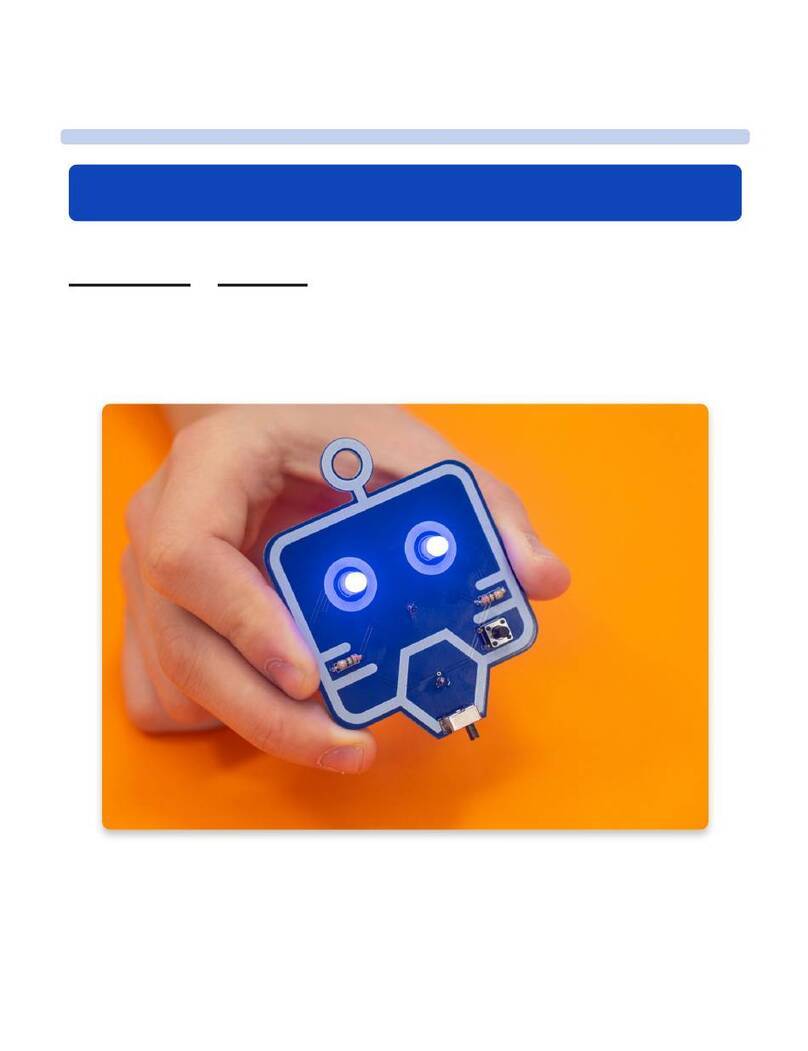
Circuitmess MR. BEE The Wacky Robot User manual

introduction
The beginning
Welcome to CircuitMess MR. BEE, the wacky
robot build guide!
By following this build guide, you'll learn how to assemble your wacky robot MR.
BEE!
MR. BEE is a beginner-friendly 8-piece kit.
With MR. BEE, you'll learn, except soldering, how intentionally unbalanced motors
work.
MR. BEE, The Wacky Robot
Build Guide
1 / 21

After you finish your MR. BEE, he will vibrate, move around, and make a buzzing
sound - everything like a bee (except flying)!
Age group
This product is 9+.
Make sure to have an adult helping you with the assembly process. It's okay to ask
for help.
Assembly time
It should take you approximately 1 hour to fully assemble your MR. BEE.
Skills
You don't need to have any specific skills before getting your hands dirty with this
DIY project.
The main objective here is to have fun and learn something new.
What's in the kit?
Let's meet all the components that arrived!
2 / 21

In case something is missing, please contact us at[email protected].
Send us a photo of everything that came in the box, and we'll get back to you as
soon as possible to resolve the issue.
Here's the list of components:
1. Resistors
2. Circuit board
3. Switch
4. 3V coin cell battery
5. Battery holder
6. Vibration motor
Electronics 101
Let's learn something about the components
you've got!
1. Circuit board
The yellow bee-shaped thingy you've gotten in your kit is called a circuit board.
Professionals call this a printed circuit board or PCB.
A PCB is a laminated sandwich structure of conductive and insulating layers.
3 / 21

What does it do?
Your circuit board has two functions:
1. It holds all the electronic components in place.
2. It provides electrical connections between the electronic components.
Because of the circuit board, all electronic components can work together as a
team.
What are those tiny lines on my circuit board?
They allow electrical charges to flow between components. This way, electronic
components are powered, and they can do clever stuff using electricity.
What is my circuit board made of?
Circuit boards are usually made out of fiberglass-reinforced epoxy-laminated
sheets.
These are also referred to as “FR4” sheets.
The FR4 sheets are used as the insulating non-conductive material, and copper is
used as a conductive material.
4 / 21

If material is conductive, it conducts electricity; electrical charge can flow
through that material easily.
FR4 and copper are both sandwiched together in thin sheets, and that’s how you
get a circuit board.
Where are PCBs used?
They’re used everywhere!
In your phone, in your laptop, in your refrigerator, air conditioner. Basically, every
electronic device you use has a unique printed circuit board that makes it work.
Did you know?
A PCB is one of the most important inventions of the last 100 years.
Space travel wouldn’t be possible without them.
PCBs were invented by Paul Eisler.
He invented it in the 1930s, but the predecessors of modern-day PCBs have been
around since the age of gramophones and vacuum tube radios, just in a
somewhat different form.
2. Resistors
5 / 21

Resistors are the most basic electronic components found in almost every
electronic device.
They fall in the category of passive electronic components.
Passive electronic components do not generate electrical power and do not need
electrical power to work.
They just modify the flow of electrical energy in their own unique way.
Resistors that you have gotten in your package have a cylindrical shape and two
tiny metal legs.
We call these legs "component leads".
Resistance
Resistors have a property of resistance - they lower the amount of electrical
energy flowing through the circuit.
They “resist” the flow of electrical energy.
The unit of resistance is called ohm and it was named after German physicist
Georg Simon Ohm.
Resistors are used for tasks such as adjusting the flow of electricity through an
electronic circuit.
6 / 21

The exact value of a resistor is measured with a device called an ohmmeter.
Can we compare it to something we see in everyday life?
If we make an analogy to water flowing through pipes, the resistor is a thin pipe
that reduces the water flow.
Scientists and engineers have come up with different symbols for each and
every electronic component.
This is an electronic symbol for a resistor:
This is Georg Simon Ohm:
7 / 21

3. 3V coin cell battery
A battery is a source of electric power consisting of electrochemical cells.
Every battery stores chemicals. These chemicals cause chemical reactions and
generate electrical energy.
This battery is made out of a material called lithium.
Do you see the tiny “3V” written on the battery?
This is read as “three volts”.
Volts are the units used to describe electrical voltage.
You will see the number of volts written on almost every battery as it’s one of the
most important pieces of information about the battery.
Voltage is a type of “pressure” that drives charge through an electrical circuit.
8 / 21

Different electronic devices have different batteries with different voltages.
For example, a mobile phone has a battery of 3.7 volts, and a car has a battery of 12
volts.
Useful tip:
This particular battery size and model is called a CR2032 coin cell battery.
4. Battery holder
This battery holder is a plastic electronic component with two springy metal legs.
It is used for holding the coin cell battery in place and connecting it with the rest of
the electronic circuit.
5. Vibration motor
This component makes MR. BEE vibrate and move around.
This particular motor type has a special name - an ERM motor.
9 / 21

An ERM motor has an off-center load, and when it rotates, the centripetal force (a
force that makes a body follow a curved path) causes the motor to move.
This motor has two wires coming out of it.
The colors of the wires (red and blue) represent the polarity of the wires: blue is
negative (-), and red is positive (+).
These wires are used for connecting the motor to the power source (battery) and
powering the motor.
This is an electronic symbol of a motor:
6. Switch
The switch you got in your kit helps you turn the device on and off. You can easily
do so with one simple push.
A switch controls the flow of power to an electric device - in other words, it
connects and disconnects an electrical circuit.
Switches are used in almost every electronic device. They are found in your mobile
phone, computer, air conditioner, etc.
Historical fun fact:
An electrical switch was invented in 1884 by John Henry Holmes, who used it for
turning lights on and off.
Meet the tools!
Let’s assemble your wacky robot!
First, we’ll need some tools
Soldering iron
For the assembly, any entry-level soldering iron will suffice.
10 / 21

Although, if you plan to dive into the world of DIY projects, you should consider
getting a more expensive one with more features
You’ll also need a soldering iron stand and a small reel of rosin-cored solder.
Diagonal cutter pliers
We prefer this type shown in the picture (Plato, model 170), but any other type will
do.
Soldering sponge
Make sure your soldering toolkit has a sponge that can be used for wiping your
soldering iron clean.Make sure that the sponge isn't dripping wet or bone dry - it
should be damp.
11 / 21

Assembly
How do I solder?
One of the things you'll do as a part of Mr. Bee's assembly process is soldering!
Have you ever done that before? If your answer is no, we suggest you look at the
following few links where you'll find useful tutorials and blogs about soldering. It will
only take you 10 minutes to get into the zone and understand how it's done. Here
are the links:
Adafruit’s video tutorial featuring Collin Cunningham-A tutorial featuring
Collin Cunningham, a super charismatic electronics guru.
Adafruit’s standard soldering tutorial-A great and thorough video tutorial. An
absolute must-read, even if you know how to solder. Make sure to check the
“common soldering mistakes” section at the end.
Sparkfun’s video soldering tutorial-Another well-made how-to-solder video
tutorial.
Sparkfun’s standard soldering tutorial-A detailed tutorial made by Sparkfun.
12 / 21

Here is an awesome picture by Adafruit industries that can help you (thank you
Adafruit!):
There are several rules of soldering that everybody,
regardless of their skill level, should follow at all times.
Never inhale the dust and the fumes that can be produced by the soldering
iron!
13 / 21

Soldering iron gets hot! Do not touch the tip of the soldering iron!
Even if the soldering iron is turned off or completely disconnected from the
power source, there is still a possibility that it’s very hot and, therefore, can
cause very uncomfortable pain if touched.Always keep the soldering iron
facing away from your hands.If you’re finished soldering, unplug the soldering
iron from the power source and leave it to cool off for at least five minutes
before putting it back in your toolbox.
Clean the soldering iron!Make sure to use the sponge often and clean your
soldering iron if you wish to have an easy and simple soldering
experience.Carefully hold an end of the sponge with one hand and wipe the
tip of the soldering iron on the other end of the sponge to remove the extra
solder. Repeat the process until the tip of the iron is nice and clean.
Check your solder joints twice (at least)!
Keep the soldering iron on the stand when you’re not using it!
Know how much solder is needed!Make sure to put just enough solder.Not
too much, and not too little, since both can cause your newly-made device to
malfunction.
Don’t leave any residual solder on the board!The solder should only be on
the parts where the pins connect to the board.
Keep the rest of the board clean!
Using the soldering iron
If you're using your soldering iron for the first time or need help with cleaning its tip,
check our video tutorial.
The soldering iron is very easy to use when used properly.
14 / 21

Step 1 - plug it in
Put the soldering iron on a soldering iron stand, and plug it into a power outlet.
Step 2 - select the right temperature
15 / 21

Set the temperature to 350 degrees Celsius by turning the temperature
regulation knob on your soldering iron.
Make sure that the small black arrow points to the correct temperature, as in the
photo.
Your soldering iron is now ready to use, but give it a minute or two, so it can heat
up.
Step 3 - don't forget to turn it off when you're
finished
We’ll tell you when you’re done with soldering, and you'll unplug the iron from the
power outlet to turn it off.
Please use the metal stand every time you are not using the soldering iron to
make sure you don't burn the surface or the circuit board
Make sure to not touch the soldering iron tip for at least five minutes after you
have turned it off.
16 / 21

Let's make MR. BEE!
Part one - Vibration motor
The first component you will need while assembling your MR. BEEis a vibration
motor. Before doing anything else, you'll need to take off the sticker on the circled
part of the motor.
Now place the motor on your robot as shown in the photo:
Now is the time to use your soldering iron.
You'll have to connect the motor’s wires to two small silver dots. To do so, first,
please put a bit of solder on them.
Hold one of the wires with pliers or tweezers.
Now heat the pad with solder on it and connect the wire with it. The wire and the
soldering pad should fuse and establish a connection.
17 / 21

Do the same thing with the remaining wire and the second silver dot.
MR. BEE should look like this by now:
Part two - The switch
Now, you'll be soldering the switch.
Place the switch as shown in the photo below.
You'll need to use a bit of strength for this since it can be a bit hard for the switch to
come into the circuit board.
Now is the time to solder the switch to the circuit board. Before you do so, please
make sure that the switch is vertical to the circuit board.
Please clean your soldering iron’s tip with the sponge before soldering the switch.
Soldering these pins requires more precision since they are so close together.
After you have successfully soldered the switch, your circuit board should look like
this:
Part three - The battery holder
The battery holder is placed on the bottom side of MR. BEE like this:
Now, turn MR. BEE around and do some more soldering.
Part four - Resistors
18 / 21

First, take off the paper packaging placed on both ends of resistors.
Now take one and pull it through one of the holes, as shown in the photo below:
You’ll have to solder the resistor.
Make sure to solder it from the backside of the circuit board, as shown in the photo
below.
To make all of the legs MR. BEE needs, please, take your pliers and cut the resistor
you already soldered.
You should always solder the resistors on the back of MR. BEE (where the battery
casing is) and cut them on the front (where the motor is).
Now do that to every one of the resistors, make six legs, and solder them.
Make sure all of the solder joints look okay!
If you need help with cleaning the tip of your soldering iron, please check our video
tutorial.
Now you can put the coin cell battery into the battery holder!
Watch out; the battery needs to be put in on the right side.
The tiny plus (+) sign on the battery must be facing upwards!
Check the photo:
Please unplug the soldering iron from the power outlet. Leave it on the soldering
iron stand for at least five minutes, so it cools off before you put it away.
19 / 21

The last thing you’ll do is take the pliers and bend MR. BEE’s legs into the shape of a
real bee's legs. But, be very gentle!
You did it! Mr. BEE is assembled.
Let's turn it on!
MR. BEE buzzes and moves around!
Now that you assembled your wacky robot, it's time to see how it works!
Your MR. BEE should look like this:
Try flipping the ON-OFF switch and see your MR. BEE move around.
Well done!
Your circuit board connected all the components and helped them work together.
You can try changing the shape of the legs (but be very careful not to break
them!) - this should make MR. BEE move in a different way.
20 / 21
Table of contents
Other Circuitmess Robotics manuals
Popular Robotics manuals by other brands

Kitronik
Kitronik LINE FOLLOWING BUGGY V3 manual

SMART
SMART ROBOT CUBBY instruction manual

QB Robotics
QB Robotics qb SoftHand RESEARCH user guide

ENGINEERED ARTS
ENGINEERED ARTS Ameca Assembly instructions

Hasbro
Hasbro TIGER ELECTRONICS Robo-Chi Pets Series instruction manual

Stiga
Stiga T8523 owner's manual