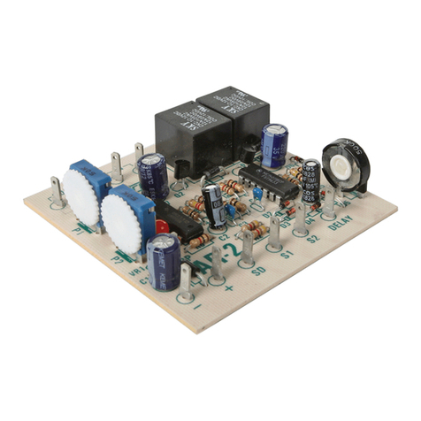
Circuitron TC-1 User manual

TURNOUT CONTROLS
TC-1, TC-2
211 RocBaar Dr., Romeoville, IL 60446
(815) 886-9010 FAX: (815) 886-9076
Electronics for Model Railroads
GENERAL DESCRIPTION: The CIRCUITRON TC-1 and TC-2 Turnout Controls provide automatic
activation of any dual-coil type switch machine when used in conjunction with any CIRCUITRON
Detection Circuit. Both units provide short, high-current pulses to the switch machine, protecting the
coils from burnout. The TC-1 has two control terminals and may be used to control both directions
of a turnout. In this way, the output from one Detection Circuit may be used to throw a turnout one
way, and the output of another Detection Circuit may be used to throw the turnout back. The TC-2
is CIRCUITRON’s Turnout Direction Alternator and it has only a single control terminal. When the
control terminal is connected to a Detection Circuit, the switch machine will be thrown one way the
first time a train is detected, and then the switch machine will be thrown the opposite way the next
time a train is detected. In this way, trains can be made to travel alternate routes around a layout,
automatically. Both the TC-1 and TC-2 require a 12 - 18 volt AC or DC input for proper operation.
The outputs on the TC-1 and TC-2 can activate one or two switch machine coils at the same time
depending upon the style of switch machine and the input voltage of the circuits.
CIRCUIT DESIGN: Both the TC-1 and TC-2 have capacitor discharge type outputs for high-current
snap-action of switch machines controlled by them. The capacitor is charged by a 200 ohm resistor
which will limit current to the switch machine should a circuit failure occur. The TC-1 contains two
identical one-shot multivibrator circuits that produce an output pulse of fixed length when the
corresponding control terminal is grounded. This output pulse drives a power darlington transistor
connected common emitter which connects the coil of the switch machine(s) to ground for the
duration of the pulse. The capacitor discharges rapidly through the switch machine coil and then
recharges in 2-3 seconds to await the next cycle. The TC-2 outputs are the same as the TC-1’s, but
the TC-2 also contains a toggle flip-flop circuit that changes states each time the input is activated.
There is additional conditioning incorporated in the circuit in the input section that is used to clean up
any oscillations that might be present from the output of the Detection Circuit that might create false
triggering of the circuit.
INSTRUCTIONS: Please refer to the diagrams for labeling and Opto-Sensor locations. The TC-1 or TC-2
can be connected with .110" solderless connectors or by soldering leads directly to the terminals on the
printed circuit board. If soldering, use a small pencil-type iron and electronics-grade rosin core 60/40 solder
(available at Radio Shack). Use only as much heat as necessary to obtain a good joint and do not wiggle the
terminal until the solder has cooled completely.
1) Mount the circuit board in a convenient location near the switch machine to be controlled. A
section of CIRCUITRON’s PCMT makes this a simple task, or the mounting pads may be drilled
out at the corners of the board and the circuit mounted with screws.
2) Connect a 20 gauge or heavier wire to the common terminal on the switch machine (see specific
instructions packed with your switch machine) and run it to the terminal on the circuit board
labeled [OUT].
3) Connect a 20 gauge or heavier wire to one of the remaining terminals on the switch machine and
run it to the terminal labeled [1] on the circuit board.
4) Connect a 20 gauge or heavier wire to the remaining terminal on the switch machine and run it to
the terminal labeled [2] on the circuit board.
5) Connect the Control Terminals ([C1] & [C2] on the TC-1, [C] on the TC-2) to the output(s) of any
CIRCUITRON Detection Circuit using light gauge wire. The DT-4 is ideal for this application. The
Opto-Sensor supplied with the Detection Unit should be located at the point where it is desired to
have the switch machine activated. In this way, the switchpoints will be thrown when the first
piece of rolling stock passes over the Opto-Sensor.
6) Connect a source of 12-18 volts AC or DC to the INPUT Terminals. CAUTION: See Notes Below
7) Manual pushbuttons may be connected as shown in the diagrams below.

NOTES:1) Input must be DC if the Turnout Control and the DT-4 are to be powered by the same
supply. 2) Maximum power will be attained in the Turnout Control Circuit when it is powered by an AC
or unfiltered DC supply. Use of a filtered or regulated supply is not recommended since inadequate
power may be stored in the capacitor with this type of supply. Separate supplies for the Turnout
Control and the DT-4 may be used if they share a common ground connection as shown in Figure 2.
3) Pushbuttons for manual operation may be added to the Turnout Controls by connecting them
between the Negative power supply connection and the Control Terminal(s) [C1, C2 or C] as shown in
Figure 1. If an AC supply is being used, the Negative connection is obtained by hooking the wire to the
Negative lead on the large capacitor near the Control terminals on the board (see Figure 2.) 4) The TC-
1and TC-2 circuits may be triggered by reed switches mounted in the roadbed and activated by a
magnet mounted below the locomotive. Connect the reed switch between (-) and the Control Terminal
as in the Manual Pushbutton example above. The Detection Unit such as the DT-4 is not needed in this
case. 5) Please note the direction of train traffic necessary with the TC-2. Traveling in the opposite
direction may cause derailments when the train crosses the Opto-Sensor. This is not a factor with the
TC-1 and bi-directional traffic is possible. 6) If the switch machine throws in the wrong direction in the
TC-1 hookup, reverse the [1] and [2] leads.
In the application in Figure 1. above, a train approaching the turnout on track A will throw the points
automatically so as to prevent derailment. Similar action will occur for trains approaching on track B,
but the points will be thrown the opposite way. As the train proceeds and approaches the second
turnout, the TC-2 will throw the points to direct
the train onto track C or D. The next train to
approach this turnout will activate the TC-2 which
will then throw the points the opposite way. This
action will continue with each successive train
taking track C and D
alternately.
WARRANTY
CIRCUITRON warrants this device against defects in materials and workmanship for a period of one year from the date of
purchase. This warranty covers all defects incurred in normal use of the device and does not apply in the following cases:
a) damage to the device resulting from abuse, mishandling, accident or failure to follow operating instructions.
b) if the device has been serviced or modified by other than the CIRCUITRON factory.
EXCEPT AS MENTIONED ABOVE, NO OTHER WARRANTY OR GUARANTEE, EXPRESS OR IMPLIED INCLUDING
MERCHANTABILITY, ON THE PART OF THE UNDERSIGNED OR ANY OTHER PERSON, FIRM OR CORPORATION, APPLIES
TO THIS DEVICE.
CIRCUITRON, INC.
Figure 1.
Figure 2. Connecting a
common ground between
different power supplies.
This manual suits for next models
1
Table of contents
Other Circuitron Controllers manuals
Popular Controllers manuals by other brands

LOVATO ELECTRIC
LOVATO ELECTRIC RGAM40 instruction manual
Carel
Carel pCO3 series Technical leaflet

National Instruments
National Instruments FELDPoint FP-2000 quick start guide
Druck
Druck PACE5000 instruction manual

Milesight
Milesight UC300 user guide

Johnson Controls
Johnson Controls LN Series installation instructions
WAREMA
WAREMA BACnet 4M230.8I AP installation instructions
Victron energy
Victron energy Bluesolar-5 manual

Pacific Power Source
Pacific Power Source UPC-3 Operation manual
Aube Technologies
Aube Technologies TH146-P-2H1C installation guide
Barber-Colman
Barber-Colman DYNA 8000 Technical manual
Biegler
Biegler autopress e Instructions for use
