manuals.online logo
Brands
  1. Home
  2. •
  3. Brands
  4. •
  5. WAREMA
  6. •
  7. Controllers
  8. •
  9. WAREMA BACnet 4M230.8I AP User manual

WAREMA BACnet 4M230.8I AP User manual

1
warema_2051514_alhb_en_v2•2022-07-01 We reserve the right to make technical modifications
General information
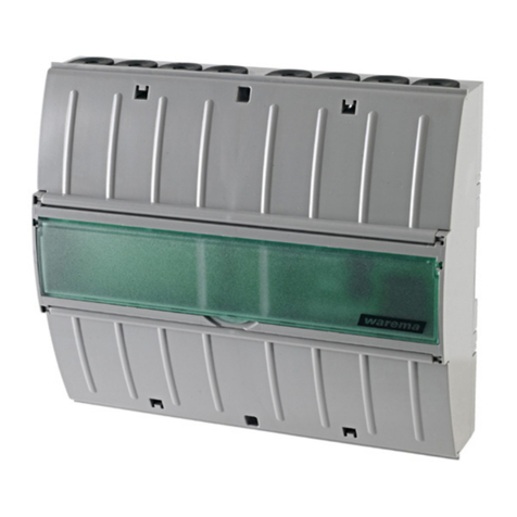
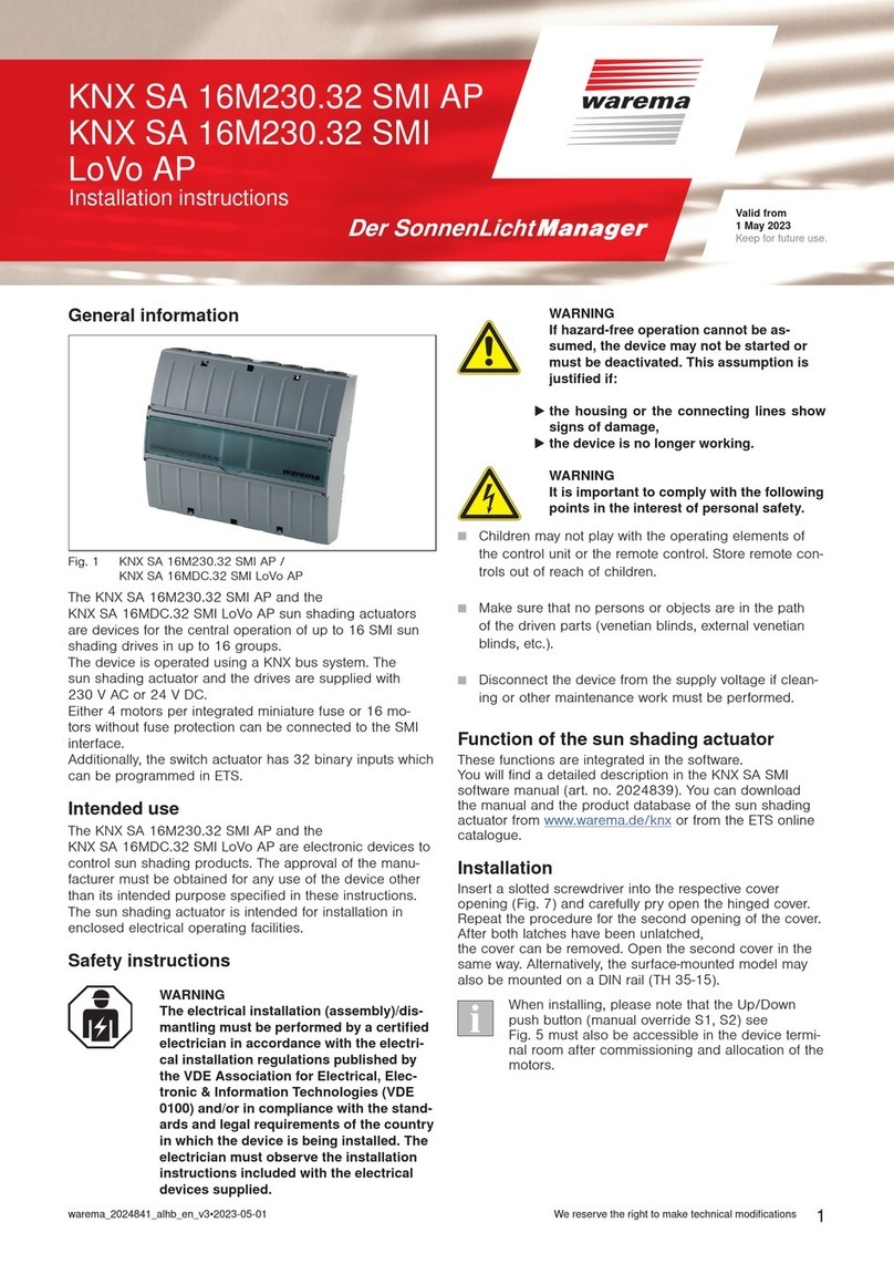
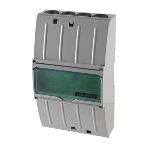
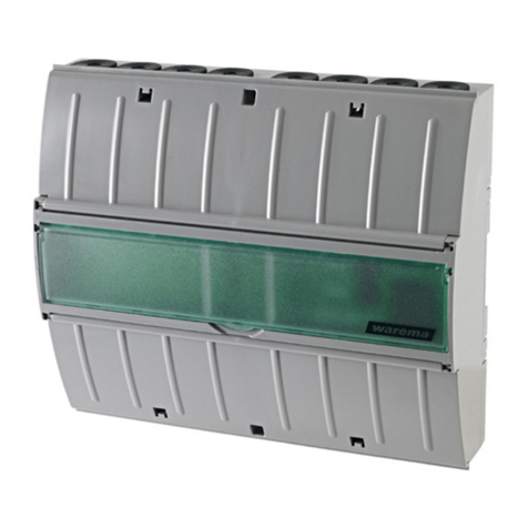
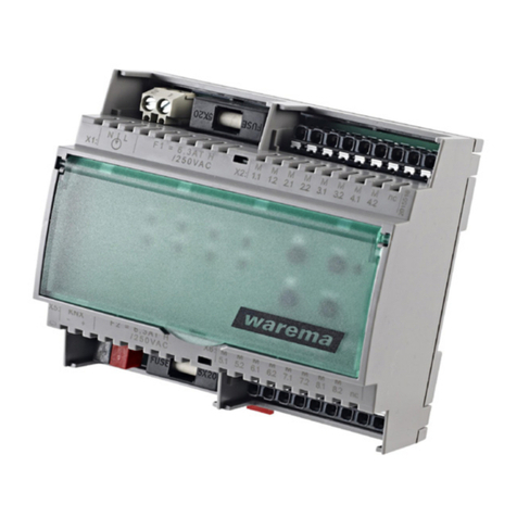
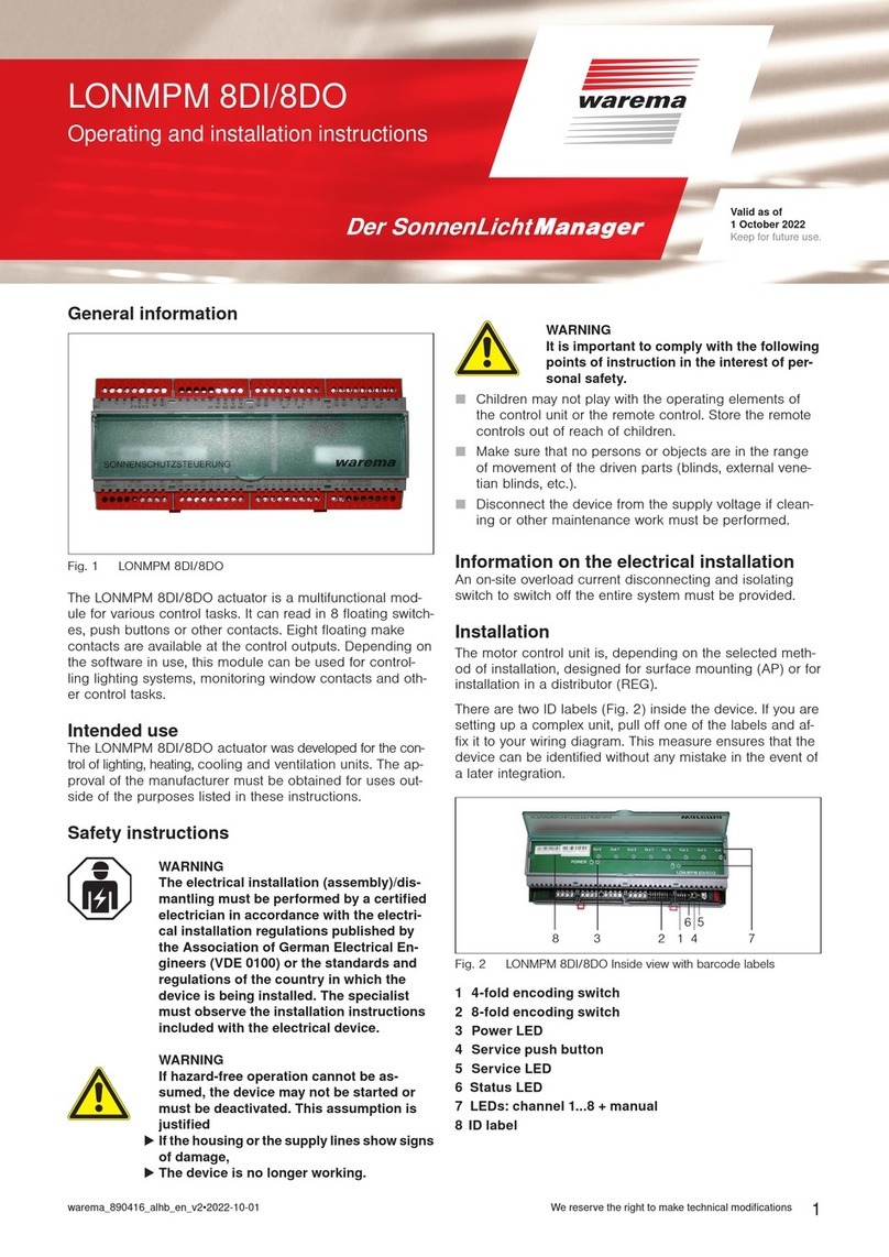
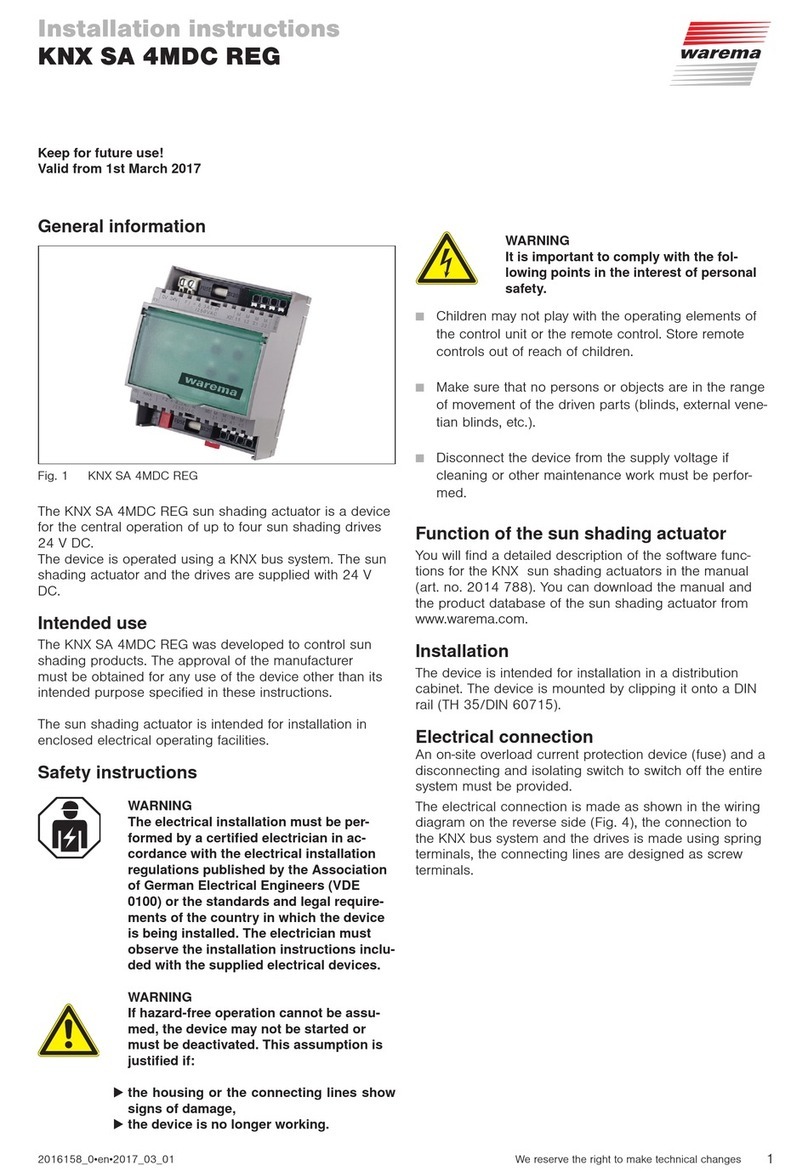
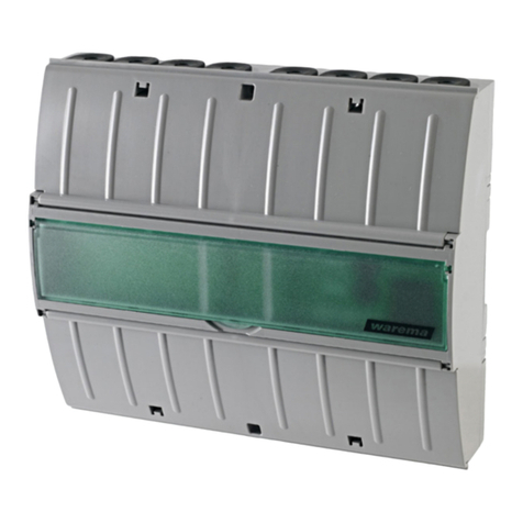
Fig. 1 WAREMA BACnet 4M230.8I AP
The WAREMA BACnet 4M230.8I AP sun shading actuator
with 8 digital inputs and 4 relay outputs is a device for the
operation of four sun shading drives 230VAC (the fol-
lowing uses the sun shading actuator for four motors with
eight push button inputs as an example).
A BACnet client can be used to switch and query the
inputs and outputs via standard objects. The digital inputs
are suitable for floating external push buttons. Under the
cover, the device has a manual control level for the outputs
(see
Fig. 5) and two encoding switches for setting the actuator
address and the baud rate.
The drives and the motor control unit are supplied via a
230VAC control line.
Intended use
The BACnet 4M230.8I AP is an electronic device for con-
trolling sun shading devices. The approval of the manufac-
turer must be obtained for any use of the device other than
its intended purpose specified in these instructions.
Safety instructions
ARNINGW
The electrical installation (assembly)/dis-
mantling must be performed by a certified
electrician in accordance with VDE0100
and/or with the standards and legal require-
ments pertaining to the respective country.
The electrician must observe the installa-
tion notes and instructions included with
the electrical devices supplied.
ARNINGW
If it a hazard-free operation cannot be
assumed, the device must not be started
or must be deactivated. This assumption is
justified if:
the housing or the connecting lines show
signs of damage,
the device is no longer working.
ARNINGW
It is important to comply with the following
points in the interest of personal safety.
 Children may not play with the operating elements of
the control unit or the remote control. Store remote
controls out of reach of children.
 Make sure that no persons or objects are in the path of
the driven parts (internal and external venetian blinds,
etc.).
 Disconnect the device from the operating voltage if
cleaning or other maintenance work must be per-
formed!
Function
A functional description of the
WAREMA BACnet 4M230.8I AP can be found in the
manual (art. no.2051515).
PICS (Protocol Implementation Conformance Statement)
and BIBBs (BACnet Interoperability Building Blocks) can be
found in the software manual (art. no.2053952).
Documents pertaining to the sun shading actuator can be
downloaded from
www.warema.de/bacnet .
Installation
Insert a slotted screwdriver (recommendation: 3.0 - 4.0mm
blade) into the respective cover opening (Fig. 4) and care-
fully pry open the hinged cover. Repeat the procedure for
the second opening of the cover. After both latches have
been unlatched,
the cover can be removed.
Electrical connection
An on-site overload current protection device (fuse) and a
disconnecting and isolating switch to switch off the entire
unit must be provided.
The unit is electrically connected according to the wiring
diagram on the other side of the page (Fig. 5).
Installation instructions
WAREMA BACnet
4M230.8I AP
Valid from
1st July 2022
Keep for future use.
warema_2051514_alhb_en_v2•2022-07-01We reserve the right to make technical modifications
2
ARNINGW
After installation, all terminals and connec-
tions under current must be completely
closed by the latched cover to prevent acci-
dental contact. It should not be possible to
open the latched cover without using tools.
Commissioning
After completing the installation work and applying the
operating voltages, the settings can be made on the sun
shading actuator.
A detailed description of the required BACnet PICS can be
found under PIC (art. no. 2051515).
The functional description (FB) can be found under art. no.
2051541.
Local operation at the actuator (manual)
Pressing button briefly = Step / Stop or Tilt
Black push button, long press = Move UP (lower run time)
Red push button, long press = Move DOWN (lower run
time)
Adjusting the baud rate
Use the encoding switch to adjust the baud rate.
Factory setting: 38400 Bit/s
To do this, perform the following steps.
 Switch on the operating voltage of the device.
Baud
rate 9600 19200 38400 57600 76800 115200
Encod-
ing 1
off on off on off on
Encod-
ing 2
off off on on off off
Encod-
ing 3
off off off off on on
ON
123
= 38400
Fig. 2 Encoding switch for baud rate
Adjusting the actuator address
Use encoding switches 1 - 8 to adjust the actuator ad-
dress. Address range: 00 to FF (FF = broadcast)
0 × 2 = 0
1 × 2 = 2
0 × 2 = 0
1 × 2 = 8
0 × 2 = 0
0 × 2 = 0
0 × 2 = 0
0 × 2 = 0
10
ON
12345678
Fig. 3 Encoding switch for actuator address
Description
Description LED display
Existing operating voltage Green LED
Receiving a valid command from the
master
Green LED
goes out briefly
Address set to "FF" Red LED
Communication error, CRC ERROR Red LED
Communication error, Framing ER-
ROR
Red LED
Incomplete frames Red LED
Input bridged Yellow LED
Output active Yellow LED
Maintenance
There are no parts inside the device that require mainte-
nance. In the event of a malfunction, the built-in miniature
fuses should only be replaced by a certified electrician.
Liability
Failure to comply with the product information in these in-
structions and any use of the device other than its intended
use may result in the manufacturer refusing to honour
warranty claims for product damage. In this case, liability
for secondary harm to persons or damage to property will
also be excluded. Observe the information in the operating
instructions for your sun shading system. The automatic
or manual operation of the sun shading system while iced
over and the use of the sun shading system during severe
weather may cause damage and must be prevented by the
operator through suitable precautions.
Cleaning
Clean the housing with a soft, dry cloth. Do not use deter-
gents, cleaning agents, solvents, abrasive substances or
steam cleaners!
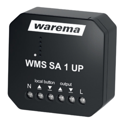
Obligations for the disposal of electrical
devices
A marking with this symbol indicates the following
obligations under the scope of legal regulations:
 The owner of this electrical device must dispose of it
separately from unsorted municipal waste for further
recycling.
 Used batteries and accumulators that are not enclosed
in the old device, as well as lamps/bulbs that can be
removed from the old device without breaking, must be
disposed of separately.
 Distributors of electrical devices and disposal compa-
nies are obliged to take back the equipment free of
charge.
 The owner must take it upon themselves to delete any
personal data contained in the electrical device prior to
disposal.
3
warema_2051514_alhb_en_v2•2022-07-01 We reserve the right to make technical modifications
Technical data
BACnet 4M230.8I AP min. typ. max. Unit
Operating voltage 198 230 253 VAC
Mains frequency 50 50 60 Hz
Power consumption in standby
mode at 230VAC
0.7 - 2.3 W
Output per drive*
Switching capacity 230VAC/
cosφ = 0.6
500 VA
*The total power per fuse must not exceed 1000VA.
BACnet interface
Protocol BACnet MS/TP
Address range for BACnet 0 - 255 (0x00 to 0xFF)
Bus interface RS485 (two-wire bus) with
potential equalisation in bus/
line topology, terminate with
120Ω (see Fig. 5, terminal
X11) and activate BIAS resis-
tors in the router.
Transmission format 8 N 1
BACnet device profile
BACnet Application Specific Controller (B-ASC)
BACnet MS/TP in accordance with ISO 16484-5:2017
BACnet Protocol Revision 16
Inputs, local operating elements
Current, active 0.5 1 1.5 mA
Ambient conditions
Operating temperature 0 50 °C
Storage temperature 0 70 °C
Humidity
(not condensing)
10 40 85 %Frel
Degree of soiling 2
Connection
Connecting line Spring terminal U/Contact
Permissible line cross-section max. 2.5mm²
Stripping length min. 8mm
Motor outputs Spring terminals
Permissible line cross-section max. 2.5mm²
Stripping length min. 8mm
Inputs Spring terminals
Permissible line cross-section max. 2.5mm²
Stripping length min. 8mm
BACnet interface Spring terminals
Permissible line cross-section 0.6 - 0.8mm∅
Stripping length 5 - 6mm
Housing
Dimensions See Fig. 4
Surface-mounted housing
degree of protection
IP30
Safety class
(PE is looped through)
I
Miscellaneous
Conformity Specified under
www.warema.de/ce
This device complies with the EMC directives for use in
residential and commercial areas.
Article numbers
BACnet 4M230.8I AP 2047065
Strain relief set
for surface-mounted hous-
ing
1002236
WAREMA Renkhoff SE
Hans-Wilhelm-Renkhoff-Strasse 2
97828 Marktheidenfeld
Germany
Fuse protection
BACnet 4M230.8I AP Quan-
tity Fuse protection
BACnet 4M230.8I AP 1 x 6.3ATH
3 ‒ 4 mm
158 mm
119 mm
132 mm
180 mm
60 mm
Fig. 4 Surface-mounted housing dimensions
warema_2051514_alhb_en_v2•2022-07-01We reserve the right to make technical modifications
4
Jumper
6,3 AT H
250 V / 5x20mm
231
M∼
Motor 1
231
M∼
Motor 2
231
M∼
Motor 3
231
M∼
Motor 4
sun shading systemsun shading systemsun shading systemsun shading system
NPE NPE NPE NPE
BU
GNYEBK BN
BU
GNYEBK BN
BU
GNYEBK BN
BU
GNYEBK BN
Bus A -
Bus B +
YCYM 2×2×0.8 mm
Bus Bus
0 V
Bus A -
Bus B +
0 V
to next bus device
2PE
N
L
connecting line
230 V AC,
50/60 Hz, 16 A,
3 x 1.5 mm²
All bus lines
from previous bus device
Attention:
Only one motor can be connected
per motor terminal set!
If interconnected, the motor
will be damaged!
The total power (of all 4 outputs)
per fuse must not
exceed 1000VA.
All motor lines
H05-RR-F 4 G 0.75 BK,
type WAREMA
All push button lines
JY(St)Y 2×2×0.8 mm
Max. line length 200m
for interference-proof routing,
use a twisted paired line.
Fig. 5 Connection example BACnet 4M230.8 AP

This manual suits for next models

1

Other WAREMA Controllers manuals

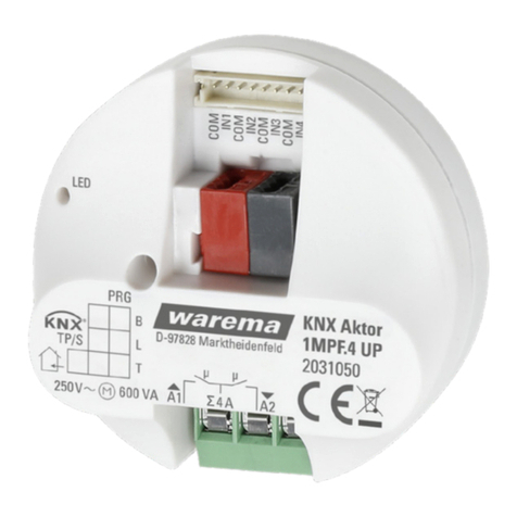
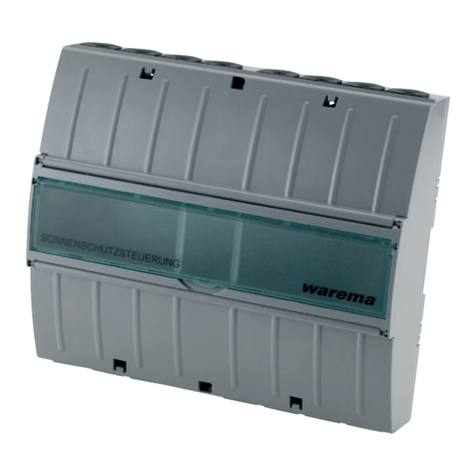
WAREMA KNX MSE 6M230 Series User manual

WAREMA

WAREMA KNX MSE 6M230 Series User manual

WAREMA KNX SA 4MDC.8 AP User manual

WAREMA

WAREMA KNX SA 4MDC.8 AP User manual

WAREMA KNX 2024236 User manual

WAREMA

WAREMA KNX 2024236 User manual

WAREMA WMS SA 1 UP User manual

WAREMA

WAREMA WMS SA 1 UP User manual

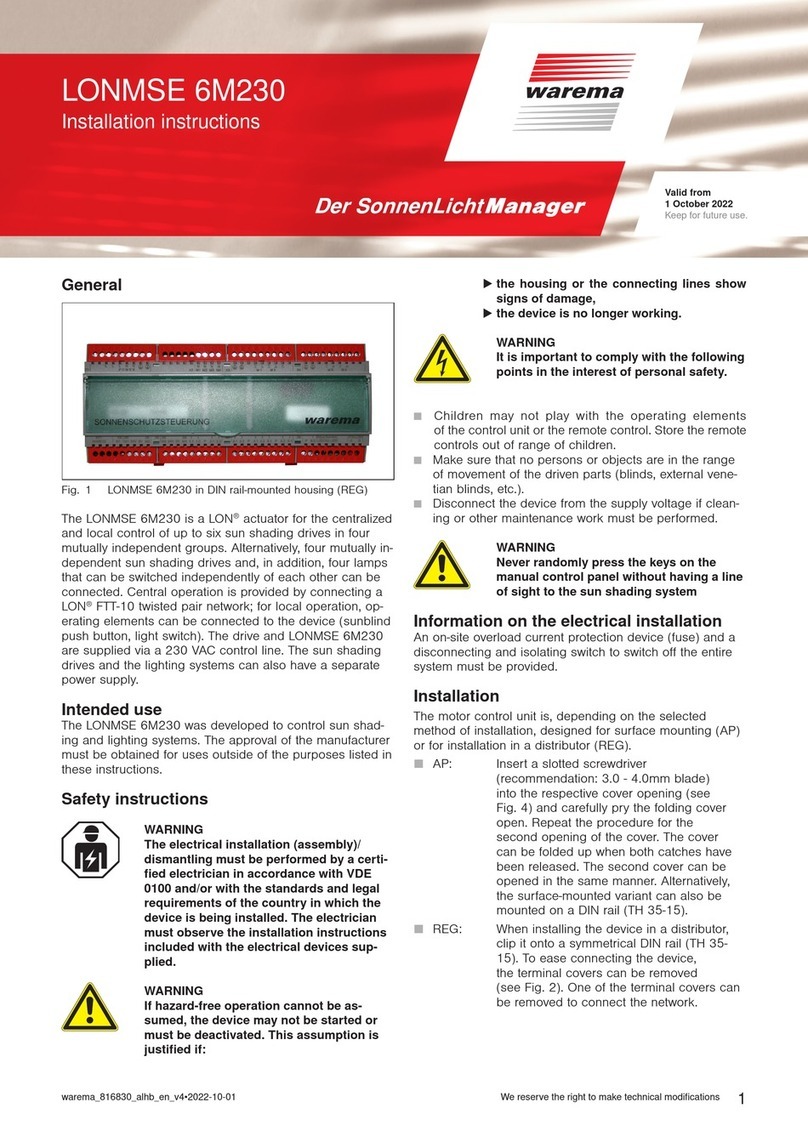
WAREMA LONMSE 6M230 User manual

WAREMA

WAREMA LONMSE 6M230 User manual

WAREMA KNX SA 16M230.32 SMI AP User manual

WAREMA

WAREMA KNX SA 16M230.32 SMI AP User manual

WAREMA Omnexo 2M230 REG User manual

WAREMA

WAREMA Omnexo 2M230 REG User manual

WAREMA LONMSE 2M230 Manual

WAREMA

WAREMA LONMSE 2M230 Manual

WAREMA KNX SA 16M230 SMI REG User manual

WAREMA

WAREMA KNX SA 16M230 SMI REG User manual

WAREMA KNX secure Series User manual

WAREMA

WAREMA KNX secure Series User manual

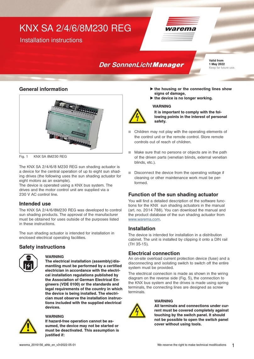
WAREMA KNX SA Series User manual

WAREMA

WAREMA KNX SA Series User manual

WAREMA KNX SA 4MDC REG User manual

WAREMA

WAREMA KNX SA 4MDC REG User manual

WAREMA Omnexo 1M230 UP User manual

WAREMA

WAREMA Omnexo 1M230 UP User manual

WAREMA KNX SA 2M230 AP Series User manual

WAREMA

WAREMA KNX SA 2M230 AP Series User manual

WAREMA 1MPF.4 UP User manual

WAREMA

WAREMA 1MPF.4 UP User manual

WAREMA LONMPM 8DI User manual

WAREMA

WAREMA LONMPM 8DI User manual

WAREMA KNX SA 2M230 REG User manual

WAREMA

WAREMA KNX SA 2M230 REG User manual

WAREMA KNX SA 16M230.32 SMI AP User manual

WAREMA

WAREMA KNX SA 16M230.32 SMI AP User manual

WAREMA Omnexo 2M230 AP User manual

WAREMA

WAREMA Omnexo 2M230 AP User manual

WAREMA KNX SA 4MDC.8 AP User manual

WAREMA

WAREMA KNX SA 4MDC.8 AP User manual

WAREMA KNX SA 2M230 REG User manual

WAREMA

WAREMA KNX SA 2M230 REG User manual

WAREMA 4M230.12 2Down REG User manual

WAREMA

WAREMA 4M230.12 2Down REG User manual

WAREMA KNX secure Series User manual

WAREMA

WAREMA KNX secure Series User manual

WAREMA LONMSE 2M230I Manual

WAREMA

WAREMA LONMSE 2M230I Manual

Popular Controllers manuals by other brands

Nelson ez pro instruction manual

Nelson

Nelson ez pro instruction manual

Siemens OpenAir GEB 131.1E quick start guide

Siemens

Siemens OpenAir GEB 131.1E quick start guide

Azbil BC-R25 Series user manual

Azbil

Azbil BC-R25 Series user manual

ascon TLK72 B operating instructions

ascon

ascon TLK72 B operating instructions

Forcepoint C1015 Hardware guide

Forcepoint

Forcepoint C1015 Hardware guide

Adtech ADTECH9 Series Programming manual

Adtech

Adtech ADTECH9 Series Programming manual

GE SX Series Installation and operation manual

GE

GE SX Series Installation and operation manual

Venmar 40455 Installation and owner's guide

Venmar

Venmar 40455 Installation and owner's guide

CARLO GAVAZZI RSBT Series troubleshooting guide

CARLO GAVAZZI

CARLO GAVAZZI RSBT Series troubleshooting guide

MarineKinetix MK4+ user manual

MarineKinetix

MarineKinetix MK4+ user manual

Skov DOL 834 Technical manual

Skov

Skov DOL 834 Technical manual

Carel IR32M manual

Carel

Carel IR32M manual

Siemens Flowrite 599 Series installation instructions

Siemens

Siemens Flowrite 599 Series installation instructions

Logitech G FLIGHT THROTTLE QUADRANT user guide

Logitech G

Logitech G FLIGHT THROTTLE QUADRANT user guide

Spa Power SP500A Mk2 user guide

Spa Power

Spa Power SP500A Mk2 user guide

Savant Director Lite HST-DIRECTORLITE Quick reference guide

Savant

Savant Director Lite HST-DIRECTORLITE Quick reference guide

Pride Controller GC2 Operation instructions

Pride

Pride Controller GC2 Operation instructions

AQUAESTIL FDS062 Series user manual

AQUAESTIL

AQUAESTIL FDS062 Series user manual

manuals.online logo
manuals.online logoBrands
  • About & Mission
  • Contact us
  • Privacy Policy
  • Terms and Conditions

Copyright 2025 Manuals.Online. All Rights Reserved.