Circutor eHome Series User manual

eHOME Series
INSTALLATION GUIDE
(M094A01-03-23A)

eHOME
2Installation Guide
eHOME
3Installation Guide
Disclaimer
Revision log
Date Revision Description
12/20 M094A01-03-20A Initial Version
06/21 M094A01-03-21A
Changes in the following sections:
1.- 2.- 3.- 5.B.- 5.C.- 5.F.- 5.G.- 5.H.- 5.I.- 5.J.-
5.K.- 6.- 7.
08/22 M094A01-03-22A Changes in the following sections:
2.- 5.- 5.C.- 5.F.- 5.G.-5.H.- 5.I.- 5.M.- 6.- 7.
05/23 M094A01-03-23A Changes in the following sections:
2.B.- 5.C.- 5.H.- 5.I.- 5.L.- 7.
Disclaimer
CIRCUTOR S.A.U. reserves the right to make modifications to the device or the unit specifications set
out in this instruction manual without prior notice.
CIRCUTOR S.A.U. on its web site, supplies its customers with the latest versions of the device speci-
fications and the most updated manuals.
www.circutor.com

eHOME
4Installation Guide
eHOME
Installation Guide
COPYRIGHT INFORMATION
This document is copyrighted, 2023 by CIRCUTOR S.A.U.. All rights are reserved. CIRCUTOR S.A.U.
reserves the right to make improvements to the products described in this manual at any time
without notice.
No part of this manual can be reproduced, copied, translated or transmitted in any form or by any
means without the prior written permission of the original manufacturer. Information provided in
this manual is intended to be accurate and reliable. However, the original manufacturer assumes no
responsibility for its use, or for any infringements upon the rights of third parties that may result
from its use.
All other product names or trademarks are properties of their respective owners.

eHOME
5Installation Guide
Contents
Disclaimer.......................................................................................................................................................... 3
Revision log....................................................................................................................................................... 3
Contents ............................................................................................................................................................ 5
1.- So, hello! ......................................................................................................................................................................6
2.- Before the installation .............................................................................................................................................8
A.- Important Safety Instructions .............................................................................................................8
B.- Electrical wiring considerations.......................................................................................................... 9
3.- Overview....................................................................................................................................................................10
4.- Dimensions ............................................................................................................................................................... 12
5.- Installation ................................................................................................................................................................ 14
A.- Space requirements.............................................................................................................................15
B.-Opening the unit................................................................................................................................... 16
C.- Power supply line and data cable insertion ................................................................................... 18
D.- Positioning............................................................................................................................................20
E.- Fixing.......................................................................................................................................................21
F.- Electrical installation ........................................................................................................................... 22
G.- Power Supply Line Connection ......................................................................................................... 23
H.- Current Limit Selector.........................................................................................................................24
I.- CirBEON (Optional)................................................................................................................................25
J.- Remote control function .....................................................................................................................28
K.-Modbus RS-485 Connection ..............................................................................................................29
L.- Closing the Charge Point....................................................................................................................30
M.- Verification............................................................................................................................................31
6.-Technical Data ..........................................................................................................................................................32
7.- Modbus register map ...........................................................................................................................................34
Need help?...................................................................................................................................................... 37
Guarantee........................................................................................................................................................ 37

eHOME
6Installation Guide
1So, hello!
eHOME
7Installation Guide
This manual provides commissioning information about eHOME series, which has been designed and
tested to allow electric vehicle charging according to IEC 61851-1:2017
This document has different sections such as step-by-step installation procedure and technical data.
THE FOLLOWING SYMBOLS ARE USED FOR IMPORTANT
SAFETY INFORMATION IN THIS DOCUMENT
ELECTRIC RISK
Take precautions to make the electrical connection inside the unit.
Unit must be disconnected from any power source during
commissioning.
ATTENTION!
Indicates that the damage to property can occur if appropriate
precautions are not taken
• Complies with IEC 61851, Electric vehicle conductive charging system (IEC 61851-
1:2017 and IEC 61851-21-2:2018).
• Complies with IEC 62196, Plugs, socket-outlets, vehicle couplers and vehicle inlets
(IEC 62196-1 and IEC 62196-2).
• Directives: 2014/35/UE, LVD;2014/30/UE, EMC
1So, hello!
eHOME
8Installation Guide
A Important Safety Instructions
Read carefully all the instructions before starting in order to
ensure properly installation of the Charge Point.
The Charge Point is designed for installation in indoor and outdoor areas. For each of the different
conditions of installation, the device must be installed safely and ensure adequate protection.
• Charge Point must not be installed in areas where
there is potential risk of explosions.
• Do not use any adapter, except those
approved by the EV manufacturer. Adapter
only allowed to eHOME models with
socketoutlet.
• Do not install the Charge Point where falling
objects may damage the equipment.
• Do not make repairs or manipulations with
the unit energised.
• The Charge Point can be installed in locations with
non-restricted access.
• Only trained and qualified personnel should
have access to low-voltage electrical parts
inside the unit.
• The surface where the Charge Point is placed must
withstand the mechanical forces.
• Check the installation annually by qualified
technician.
• Do not use this unit for anything other than
electric vehicle charging modes are expected in
IEC 61851.
• Remove from service any item that has
a fault that could be dangerous for users
(broken plugs, caps that don’t close...).
• Do not modify this unit. If modified, CIRCUTOR will
reject all responsibility and the warranty will be
void.
• Use only CIRCUTOR supplied spare parts.
• The Charge point does not support the ventilation
optional function described in IEC 61851-1:2017
(clause 6.3.2.2).
• Do not use this product if the enclosure or
the EV connector is broken, cracked, open, or
shows any other indication of damage.
Refer to TECHNICAL DATA section for more information about environmental installation conditions.
2Before the installation

eHOME
9Installation Guide
B Electrical wiring considerations
Take into consideration this section before start wiring
connections of the Charge Point.
1. ELECTRICAL PROTECTIONS
Charge point may not include elements of electrical protection.
If this device has internal electrical protections, they are installed in each socket-outlet for the
protection of the user against an electrical failure, according to the international standard IEC 61851-
1.
In order to guarantee the total protection of the users and the installation (power supply line
included) in front of any electrical hazard, it is mandatory to install a main circuit breaker (MCB) and
a residual current device (RCD) upstream of the charger.
These electrical protections and the rest of the installation have to be aligned with the local and
national rules. The selectivity of the protections has to be guaranteed at all times.
3. POWER SUPPLY LINE DIMENSIONING
The dimensioning of the input power supply line of the Charge Point must be checked by a qualified
electrician. Note that various factors such as cable length between distribution board and Charge
Point, maximum output current of the Charge Point may have influence of the selected cable.
In such cases, increasing the cable cross-section it is required to adapt the temperature resistance
of the power supply line.
3. MAXIMUM OUTPUT CURRENT
Please refer to the TECHNICAL DATA section to consult the default factory settings from maximum
output current of the Charge Point.
If the power supply is less than maximum output current and adjustment to a lower nominal current
needs to be performed, please refer to the current limit selector section.
2Before the installation
eHOME
10 Installation Guide
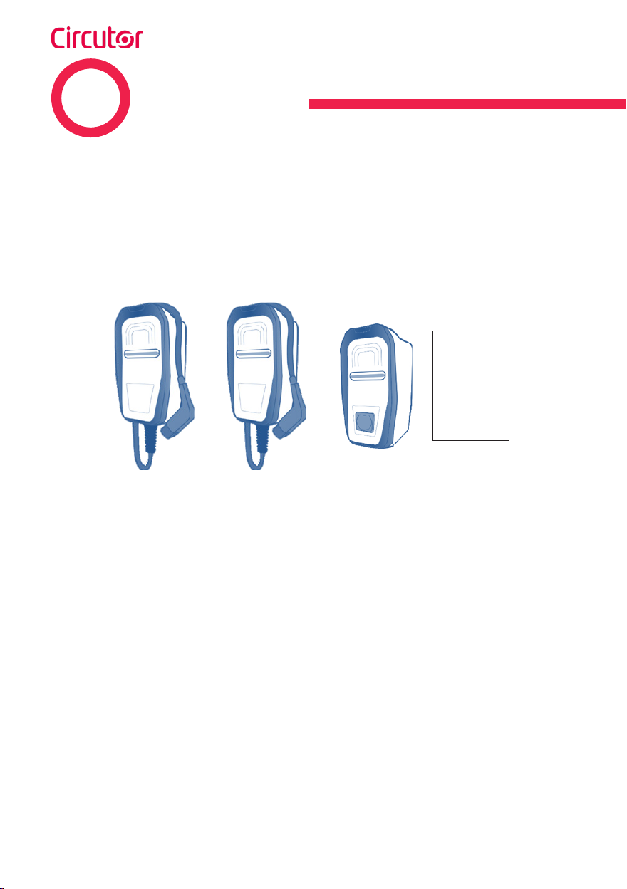
Short description
The eHOME Charging Point is specially designed to be easily installed both in outdoor and indoor
private car parks, in order to charge all the EV models of the market in mode 3 (according to European
standard IEC 61851-1), by just connecting either its tethered cable with a Type 1 or Type 2 connector
or connecting the EV cable into the charger socket Type 2.
Items included:
or or
Installation
Guide
Charge Point Installation
Guide
The eHOME Series can includes the RS-485, with interface Modbus in order to be managed by an
external master device through it.
3Overview

eHOME
11Installation Guide
3
2
6
4
5
7
1
Description
1CIRCUTOR Logo 5Frame
2Status RGB LED bar 6Socket
3Front cover 7Protections and Meter Door
4Cable + Connector.
3Overview

eHOME
12 Installation Guide
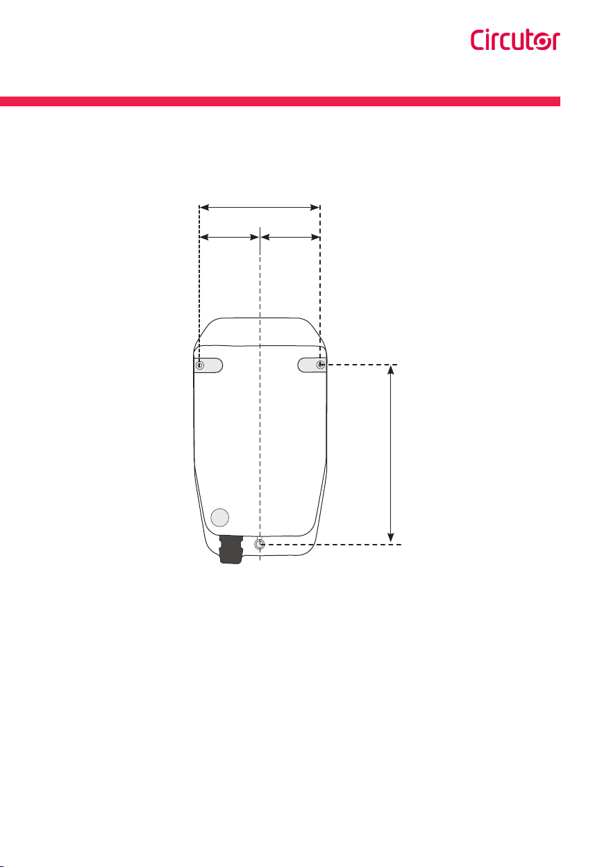
180
315
115
Measures in mm
4Dimensions
eHOME
13Installation Guide
79 79
238
158
Measures in mm
4Dimensions

eHOME
14 Installation Guide
Material:
Screws, sealing washers and plastic anchors are not included.
The installation kit has been tested on a concrete wall.
For the unit to be securely fixed in such conditions, it is recommended to use:
3 x Inox A2 wall screws: Ø3x45
3 x plastic anchors: 6x40
If the installation surface has different properties, the screws and plastic anchors must be defined
by a qualified installer.
Tools:
Screw driver Driller Tap drill 6M
5Installation
eHOME
15Installation Guide
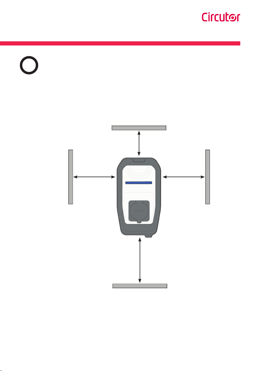
A Space requirements
When installing the unit, some space shall be reserved for usability, maintenance and safety reasons.
Please comply accordingly to your country specifications.
The next picture shows the recommended minimum distances:
Measures in mm
Front view
300
MIn. 600/ Max. 1200
300
300
5Installation

eHOME
16 Installation Guide
B Opening the unit
1.- Remove the screw at the bottom of the box.
2.- Using a screw driver, put it into the indicated marks, at the bottom of the box, and starting
removing the frame doing click at the bottom.
Beware of not breaking the plastic of the frame with the screw driver.

eHOME
17Installation Guide
3.- Grabbing the frame with the hand by the lower part, pull and take it off totally, from the bottom
to the top.
4.- Remove the six screws of the front part by using a screw driver and take out the front part of
the enclosure.
To make it easier help yourself with the screw driver while pulling the
frame off.
Be sure that the unit is not energized before going forward with the
opening procedure.
eHOME
18 Installation Guide
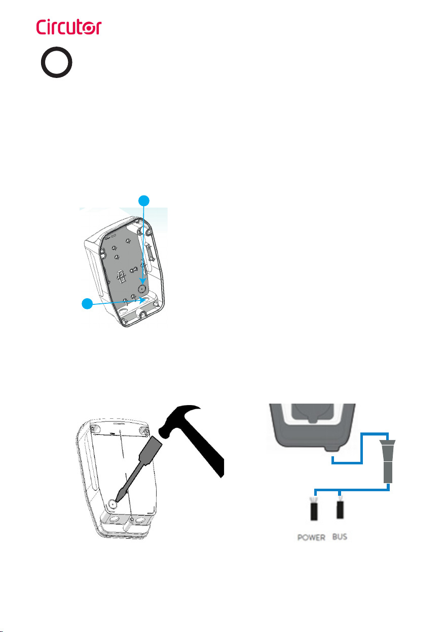
C Power supply line and data cable insertion
There are two possibilities to insert the electric wires or electric pipe:
1.- Breaking out the cable insertion opening on the rear of the housing.
2.- Using the cable insertion opening at the bottom of the housing.
In all cases it is required to install a cable gland to ensure properly installation and preserve the IP
of the unit.
1
2
1.- Cable insertion opening on the rear of the
housing (Breakable)
2.- Cable insertion opening at the bottom of the
housing
1.- POWER SUPPLY LINE CABLE INSERTION OPENING
Use a hammer and a flathead screwdriver carefully in order to break out the cable insertion opening,
as shown in the picture below.

eHOME
19Installation Guide
Do not make any other holes on the enclosure. Use only the marked
cable insertion openings to install the required electric pipes. Install
always double membrane seals to ensure IP protection of the charging
point.
Be careful of not damaging any of the inside components when
breaking out the rear cable insertion opening.
The data cable could be assimilated in the same electric pipe as the
power supply. However in order to avoid electric interference from the
power supply we recommend use FTP Cat5e or S/FTP Cat5e.
2.- USING TH BOTTOM CABLE INSERTION OPENING
Introduce the cable through the opening and fix it properly by means of the supplied M25 cable
gland.
12
Do not make any other holes on the enclosure. Use only the named
cable insertion opening to install the required electric pipes. Install
always either cable glands or double membrane seals to ensure IP
protection of the charging point.

eHOME
20 Installation Guide
D Positioning
Make holes for fastener screws.
Tap drill
M 6
Measures in mm
Front view
MIn. 600-/ Max. 1200
238
158
79
1.- Mark 3 holes taking into account the picture measurements (also written on the rear face of the
box).
2.- Place the enclosure on a flat surface.
3.- Use 3x45mm screws to fix the Charge Point to the wall.
4.- Check whether the box has any inclination using a level tool.
5.- Use Ø 6 drill size to make the 3 holes into the wall.
6.- Install the anchor according to the surface material.
Other manuals for eHome Series
2
This manual suits for next models
8
Table of contents


