IBS DBM20A User manual

IBS Intelligent Battery System GmbH
Seestrasse 24, CH-3600 Thun, Schweiz
Tel: +41 33 221 06 16
Fax: +41 33 221 06 17
-Mail: info@ibs-tech.ch
IBS-DBM20A_en_v2.2.1.doc 1
In-Car Charger 20A
with DC/DC-Converter
(New option Li-board battery)
Manual

2
Table of Content
Table of Content .....................................................................................................................................................2
Language / Sprache / Langue / Lingua .......................................................................................................................3
Product Description ................................................................................................................................................3
Warning ............................................................................................................................................................3
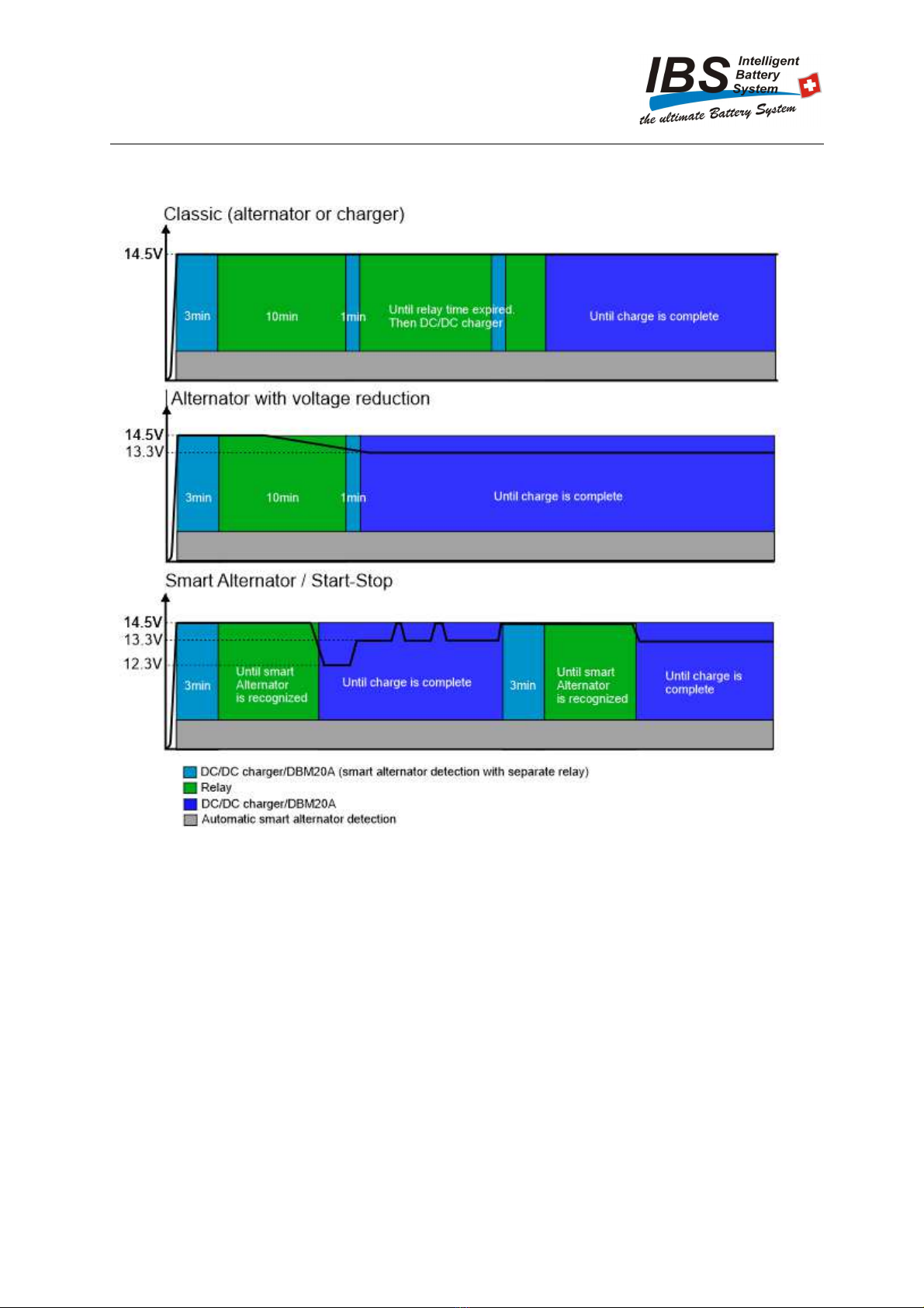
DBM20A 2.9 software for smart alternators of Euro 6d-Temp vehicles .....................................................................4
ehicles with a current sensor to ground ................................................................................................................4
Alternator types ......................................................................................................................................................5
Important settings ...............................................................................................................................................5
Applications ..........................................................................................................................................................6
Technical Informations ............................................................................................................................................6
Combinations of IBS Devices ...................................................................................................................................7
Programming the system ..........................................................................................................................................8
Procedure ..........................................................................................................................................................8
Status LED ........................................................................................................................................................8
Configuration Battery capacity .............................................................................................................................8
Charge Select Indication ..................................................................................................................................9
Notice ..........................................................................................................................................................9
Selection of charge level................................................................................................................................ 10
After configuration ........................................................................................................................................... 10
Relay Check List .......................................................................................................................................... 10
Mounting ............................................................................................................................................................ 11
Wiring extension .............................................................................................................................................. 11
Installation .......................................................................................................................................................... 11
Attention ......................................................................................................................................................... 11
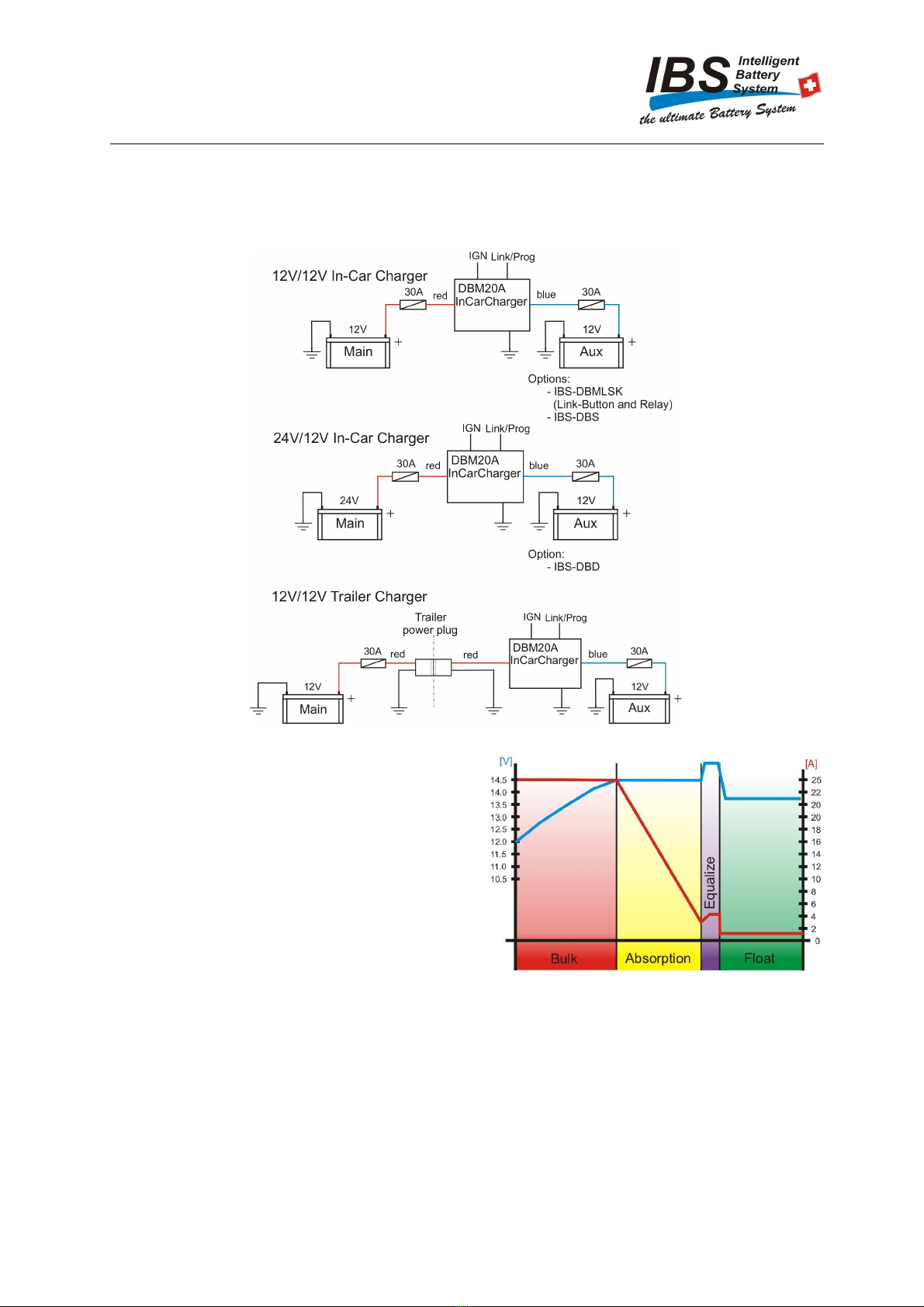
12 /12 -System without options........................................................................................................................ 12
Notice ........................................................................................................................................................ 12
12 /12 -System with Link Start Kit ................................................................................................................... 13
Extra functions with Link Start Kit IBS-DBMLSK ............................................................................................ 13
Notice ........................................................................................................................................................ 14
12 /12 -System with IBS-DBS and Relay .......................................................................................................... 15
Extra functions and applications with IBS-DBS................................................................................................. 15
DBS software version 8.1 .............................................................................................................................. 15
DBS software version 2.2 to 8.0...................................................................................................................... 15
DBS analogue versions ................................................................................................................................. 15
Notice ........................................................................................................................................................ 16
12 /12 -System in Trailer/Box ......................................................................................................................... 17
Notice ........................................................................................................................................................ 17
24 /12 -System (with optional IBS-DBD Display)............................................................................................... 18
Notice ........................................................................................................................................................ 18
24 /12 -System in Trailer/Box ......................................................................................................................... 19
Notice ........................................................................................................................................................ 19
24 / 12 parallel operation of DBM20A ............................................................................................................ 20
Solar................................................................................................................................................................... 21
Relay not found – what now? ................................................................................................................................. 22
Check ............................................................................................................................................................. 22
What are the conditions?.................................................................................................................................... 22
Start relay check ............................................................................................................................................... 22
Test of function .................................................................................................................................................... 22
Display overview.................................................................................................................................................. 23
DBM Status LED ............................................................................................................................................. 23
Charge Select LED’s......................................................................................................................................... 23
Main Battery / Aux Battery LED’s ...................................................................................................................... 23
Charge Status LED ........................................................................................................................................... 23
Relay LED ...................................................................................................................................................... 23
Error description................................................................................................................................................... 24
Error list ......................................................................................................................................................... 24
What to do / Resetting ....................................................................................................................................... 24
Alarm in combination with IBS-DBS (up to Software 8.0) ...................................................................................... 24
Specifications ...................................................................................................................................................... 25
Technical Specifications: ................................................................................................................................... 25
Accessories ......................................................................................................................................................... 25
Personal Data ....................................................................................................................................................... 26
Notes .................................................................................................................................................................. 27
Included .............................................................................................................................................................. 27

3
Language / Sprache / Langue / Lingua
For manual in another language follow the path or scan QR-Code.
Für Handbücher in einer anderen Sprache, Links folgen oder QR-Code scannen.
Pour les manuels dans une autre langue suivez le link ou scannez le code QR.
Per il manuale in una otra lingua seguite il link o scannerizzate il codice QR.
nglish Deutsch Francais Italiano
Uscita
prossimamente
http://www.ibs-tech.ch/download/manuals-ibs.html
Product Description
The IBS-DBM20A is multifunctional Dual Battery System with DC/DC charger technology.
New Alternator technologies like smart alternators or charge-reducing alternators require sophisticated
dual battery systems to function correctly.
The DBM20A can be configured with IGN-Signal (Ignition) for correct detection if the car is running and
charging. 3 different charge levels/battery types with or without an additional equalize mode are user
selectable. The 3 or 4 charge modes such as Bulk / Absorption (with optional qualize) and Float offer
an effective charge which is superior to a conventional dual battery system.
The 3 main applications are In-Car Charger 12V/12V, In-Car Charger 24V/12V and Trailer Charger
12V/12V.
When used as In-Car Charger (12V/12V) there are different IBS modules which can be combined with
the DBM20A to get special functionality or extra performance.
Before installing the DBM20A identify which alternator type is in use and which charge level the Aux
battery requires.
This model DBM20A enables the adaptation of the measurement, monitoring, control and regulation fun
ctions for Li on-board batteries (LiFePO4 with nominal voltage of approx.
12.8V). Please refer to chapter Configuration during commissioning.
Warning
The installation and the startup process should only be done by people with training and experience in
automotive electrical systems and battery technology.
The DBM is only designed to charge 12V Car batteries, like AGM, Calcium, special Li-Types and lead
acid batteries. Other batteries such as non-rechargeable batteries must not be connected to the DBM.
Some battery types produce explosive gases while charging. Installation specifications from the
manufacturer must be considered.

4
DBM20A 2.9 software for smart alternators of Euro 6d-Temp
vehicles
In the past, the alternator charged the starter battery as soon as the engine was running. Classic dual
battery systems such as the IBS-DBS or IBS-DBR, also known as VSR, Voltage Sensing Relay, charge
the auxiliary battery easily and reliably during this time.
Voltage-reducing alternators have been installed for several years, which charge normally when the
vehicle is started and reduce the charging voltage to around 13.3V over the travel time. Among other
things, this prevents the battery from being fully charged after a short time. When charging heavily
discharged auxiliary battery, this can lead to them no longer being fully charged. In some vehicles, an
ATO-Type diode can be installed in series to the alternator fuse, which increases the charging voltage
by 0.6V in classic battery systems and guarantees a fully charged starter and auxiliary battery again.
In recent years with various exhaust gas scandals, the vehicle industry has started to use smart
alternators, which only charge when no load is on the engine (downhill, gear change, braking and
sometimes shortly after the vehicle starts) and thus allegedly reduce exhaust emissions. A DC/DC
charging booster is used here, which continuously ensures a good constant charge on the auxiliary
battery.
The new IBS-DBM20A with software V2.9 and additionally installed LinkStartKit or IBS-DBS dual
battery system activates the dynamic Smart Alternator detection. The measurement of various latest
vehicles has shown that some smart alternators can switch between classic, voltage-reduced and smart
alternator charging. The IBS system monitors the alternator and changes from classic to smart charging
and shortens the charging time if possible. A DC/DC charging booster can only charge up to its
maximum charging capacity. The IBS-DBM20A with installed relay charges with the relay while the
alternator fully charges, whereby the full charging capacity of the alternator brings the auxiliary battery
to approx. 80% charge in a short time. The charging booster with the 3 to 4 charging stages (bulk,
absorption, equalize, float) finishes the charge. On long journeys, the DBM20A changes to float charge
mode at the end of charging to avoid an overcharging of the auxiliary battery.
In combination with lithium batteries, the DBM20A limits the start current to approx. 0.2C
ehicles with a current sensor to ground
For vehicles with a current sensor to earth, the -Pole connection of the auxiliary battery (Aux)
must be connected directly to the -Pole of the starter battery (Main) and not to the chassis of the
vehicle. All additionally installed consumers must be connected directly to the +/- pole of the additional
battery connected. For individual vehicle brands, the presence of the additional battery can be activated
in the system settings.

5
Alternator types
Important settings
In order for the smart alternator detection to work reliably, the IGN connection (light blue) must be
connected to the ignition or Terminal 15. This connection can be left open on vehicles with a classic
alternator.
With the battery size selection (new programming step 2, selection: small (<80Ah), mid (80-150Ah),
large (> 150Ah)), the system knows how big the additional battery is and optimizes the relay time
accordingly.
Li-ion auxiliary batteries are increasingly being used. Here it is important to correctly configure the
DBM20A for lithium (new programming step 1) so that all switching points and control parameters are
adjusted and the equalize mode is deactivated.
If an IBS-DBS is also installed on the DBM20A, it is very important that the correct programming of the
DIP switch settings (see page 8 in the IBS-DBS manual) is carried out, especially the lithium and
DBM20A configuration.
With DBM20A installations without LinkStartKit or IBS-DBS, older versions can also be used in vehicles
with Smart Alternator.

6
Applications
In this overview the three main applications are shown with their options.
Technical Informations
The DBM20A provides a 3 to 4 step charging
programm:
1. Step: Bulk
The Bulk step is the first step of
charging. In this step the battery is
charged with a constant maximal charge
current until chosen charge voltage is
reached.
2. Step: Absorption
As soon as the chosen voltage is
reached on the battery, the next step
starts. While the absorption the most energy is charged into the battery. Here the charging
current gets lower and lower while keeping the voltage constantly on chosen level.
3. Step: Optional Equalize
After current drops under 3 amps the optional equalize starts (only when configured and
only once in a month at most). In this step the charger boosts the voltage for an additional
0.6V on the battery for a certain period. This forces the sulphation to be reversed which
helps the battery to last longer and in a better state (CAUTION: not all the battery types are
made for this step or need it. Instructions and specifications provided by the battery
manufacturer must be considered!)
4. Step: Float
As the current drops below 3 amps in the absorption step, respectively equalize is finished,
the float step starts. As the charge procedure is finished at this point the charge voltage is
reduced to 13.7V to counterbalance the self-discharge of the battery without overcharging
it.

7
Combinations of IBS Devices

8
Programming the system
Procedure
1. Showing software version (automatically).
2. Battery type configuration (manually)
3. Battery capacity configuration (manually)
4. Configuration of charge level (manually)*.
5. Saving the selection (automatically).
6. Check for relay (automatically).
7. Indication if relay was found or not (automatically).
8. Change to Standby mode configuration of system is complete (automatically).
* For easy charge level selection it is most practical to leave the yellow (Prog/Link) wire open and finish
first the configuration (contacting to GND) and only connect to Link Push-Button or green wire of battery
monitor when DBM20A has switched to Stand-By mode (DBM Status L D is flashing green).
The System automatically starts up when the black (GND) and the red (+Main) wires are connected and
first shows its software version. After that all the L D’s are flashing for 30s, in this time it can be
switched in the configuration mode when the yellow (Prog/Link) wire is briefly contacted to GND.
If no change is made in one of the three configuration steps, the system automatically switches to the
next configuration step after 15 seconds with the corresponding L D flashes quickly. After a change,
the system changes to the next configuration step after only 5 seconds of inactivity. If the configuration
mode is not started, the DBM20A starts with a fast flashing pattern, in the default mode (Low
Level/Lead-Battery/80-150Ah) or the last saved configuration.
The fallowing settings can be made in the configuration mode.
Configuration Li-board battery (LiFePO4,)
If the Main Battery L D lights up green, the DBM is in the battery type
configuration. With a short ground contact of the Link/Prog wire, you can
switch back and forth between lead and Li batteries. If the DBM status
L D flashes green and red, the DBM is in the Li-battery configuration. If
the L D only flashes green, the DBM is configured for lead batteries
(default). The 2 types of batteries repeat in a cycle.
Status LED Battery type
Lead-battery
Lithium-battery
Configuration Battery capacity
If the Charge Status L D is green, the DBM is in the battery
capacity configuration. With a short ground contact of the
Link/Prog wire, you can switch between the three different sizes.
The 3 capacities repeat in a cycle.
High Level Batteries > 150Ah
Medium Level Batteries 80-150Ah
Low Level Batteries < 80Ah

9
Configuration charge setting
When the DBM is in the charging setting, the relay L D lights up
green. Six different charging modes can be set in this
configuration step. If a short ground contact is made with the Link
/ Prog line, the system switches to the next charge level. The 6
selection levels repeat in a cycle.
Charge Select Indication
Low Level Charge level Low (14.0V)
Medium Level Charge level Medium (14.4V)
High Level Charge level High (14.8V)
qualize qualize mode: Low/Mid/High +0.6V (only
temporary)
Notice
Before configuring the Charge Level determine whether qualize Mode is necessary for the Aux-Battery
and whether any appliances are connect to the Aux Battery, which could shut down due to high Charge
Voltage. For Li-board battery the Equalize mode must not be activated.

10
Selection of charge level
The default setting is Low at 14.0V without qualize. Before choosing the charge level please consider
the specifications supplied by the battery manufacturer. The qualize Mode (if activated) reformates the
battery the earliest every 30 days, this counteract the sulphation and enhances the efficiency of the
battery. The following table may be used to assist with selecting the correct Charge Level:
Low G L / LiFePO4
Medium AGM / LiFePO4
High Spiral Cell / AGM / Pb liquid / Calcium
Instructions and specifications provided by the battery manufacturer must be considered!
After configuration
The System automatically checks for an installed relay (12V Version only) and indicates if a relay was
found/ could not be found yet (restarts relay check automatically later) or no relay found.
When changing the Aux battery or to choose another Charge Level disconnect the red (+Main) wire and
the blue (+Aux) (and if used the lightblue IGN) wire from batteries and restart the configuration as in
description above with the Link/Prog wire (with installed Link-Button these contacts can be made by
pushing the Button or with installed IBS-DBS by pushing the link Button on the monitor [with IBS-DBS
make sure to push auto Button when the DBM20A changed to Stand-by mode).
Relay Check List
Directly after saving the selected charge level the system automatically starts to check if a relay is
installed. This only happens with 12V/12V systems. The relay check will not be executed if DBM20A
is used in a 24V/12V system and it directly changes to standby mode.
1. Therefore the relay will be turned on for a short time (you should hear the relay „clack“). The relay
L D is turned on.
2. After 2 seconds the relay and the relay L D will be turned off again.
3. Afterwards it will be indicated by the two main and aux battery L D’s if a relay was found or not. If
both L D’s are green the system found a relay. In case they are in orange the system didn’t yet find
a relay. In this case it will restart a relay check as soon as the engine is turned on. The L D’s are
red when there was no relay found.
4. Change to standby mode.
Is only shown for 1 second!
Main Battery L D Aux Battery L D Status
red red No relay found
orange orange It will check again later
green green Relay found
Automatic relay detection
ngine off and wait 2 minutes
Switch on ignition, switch on headlights and fan, wait 1 minute
Press the link button (button or monitor), click from the relay audible when it is recognized.

11
Mounting
Mount the DBM20A with its wires facing downwards close to the Aux Battery on metal auto-body panel
to provide the best cooling. Do not mount close to hot engine parts such as exhaust or turbo charger.
The DBM20A will typically warm to around 40°C depending on application.
If the DBM20A experiences extreme heat due to inappropriate mounting position, the system will do a
safety shut-down.
Wiring extension
If extension of the power wires red/black/blue is needed use 4mm2 wires for up to 1 additional meter, for
up to 3 additional meters use 6mm2 and if needed longer use 10mm2 (copper cross section – not
external insulation size) wires. Use 10mm2 wires to extend wires if DBM20A is mounted in a Trailer.
Installation
In this section all the installation steps are explained. Follow these steps for a correct installation.
Attention
Before Installation
Be aware of which application you are going to install. Only follow the steps for the specific
application!
The choices are
System Description Page
12V / 12V System Without options 9
12V / 12V System With Link Start Kit 10
12V / 12V System With IBS-DBS and Relay 12
12V / 12V System Trailer / Box 14
24V / 12V System With optional IBS-DBD 15
24V / 12V System Trailer / Box 16
24V / 12V System Parallel Operation 17
First read all the installation steps and the programming steps in chapter Programming the
system on page 6.
Read as well the notes for the Mounting and the Wiring extension on this page.
During installation
The red wire is always connected to main battery and the blue wire always to aux battery! If the blue
wire is connected to main battery this will lead to malfunction in a 12V/12V system and in a 24V/12V
system it can even destroy the device! Reverse battery will destroy the device!
Fuses have to be installed!
After installation
Do the control steps (The documents can be found be scanning the QR
code on the installation page or online on our homepage http://www.ibs-
tech.ch/en/document-download/test-procedures-ibs.html ).

12
12 /12 -System without options
For a better understanding of how the system is programmed first read the Programming the system
steps on page 8. Otherwise the system may need to be reinstalled.
Read the notes for the mounting and wiring extension on page 11 before starting the installation.
Please read Instructions carefully prior to installation.
Choice of light blue connection IGN:
With alternators (smart alternators) that cut off charge temporarily, connect IGN wire to Car Ignition
(Terminal 15). When the alternator turns off, the DBM20A keeps charging until the Main voltage
drops below 11.9V or the alternator kicks in again.
With all other alternators do not connect the light blue (IGN), DBM20A stops charging when the
Main voltage drops below 12.7V. The DC/DC Charging automatically starts when Main voltage is
higher than 13.3V.
1. If needed connect the light blue IGN wire on Car Ignition (Terminal 15), otherwise leave
unconnected.
2. Connect all black GND wires.
3. Connect the red wire (+main) (ATTENTION: system is starting up -> refer to page 8 Programming
the system). (Continue installation only after System has switched to Stand-By mode)
4. Connect the blue wire (+aux) last.
New parallel operation 2 DBM20A
Two DBM20A can be operated in parallel, resulting in a maximum charging current of up to 45A. This
new function is only supported if no relay is installed in the system (no link start kit or no IBS-DBS dual
battery system with relay). Depending on the load behaviour, both systems work with full power, with
partial load or low power, a DBM20A, a "loading error" status display, can be deactivated. When more
charging power is required again, the deactivated DBM20A reactivates automatically again.
Notice
For a safe installation it is necessary to install the fuses in the red wire path (+ main: 30A) and in
the blue wire path (+ aux: 30A)!

13
12 /12 -System with Link Start Kit
Extra functions with Link Start Kit IBS-DBMLSK
1 Link Start:
Vehicle can be started from Aux battery by pushing Link-button.
2 Automatic Winch support*:
the DBM20A recognises Winch usage and switches (engine has to be turned on) to Relay
Support Mode for optimal charge sharing on both batteries.
3 Manual Winch support:
30 minutes or 2 hours manual Relay Link can be activated by pushing the Link-Button once (for
30 minutes) respectively twice (for 2 hours) within 5 seconds. A reset of this mode can be
done by pushing the Link-button for 10 seconds.
4 Solar Charge:
With installed solar panel on Aux battery the Main battery will be charged as well when Aux
voltage is higher than 13.5V.
5 Fast Charge:
When the car is started the alternator first charges both Main and Aux battery (Fast Charge)
and then the DBM20A switches to DC/DC Charge to get a 100% full Charge as configured.
6 RBM Function:
Relay Booster Module Function for Link Start when a low Main battery is detected.
*Only available when IGN signal is open (light blue wire not connected)!

14
For a better understanding of how the system is programmed first read the Programming the system
steps on page 8. Otherwise the system may need to be reinstalled.
Read the notes for the mounting and wiring extension on page 11 before starting the installation.
Please read Instructions carefully prior to installation.
Choice of light blue connection IGN:
With alternators (smart alternators) that cut off charge temporarily, connect IGN wire to Car Ignition
(Terminal 15). When the alternator turns off, the DBM20A keeps charging until the Main voltage
drops below 11.9V or the alternator kicks in again.
With all other alternators do not connect the light blue (IGN), DBM20A stops charging when the
Main voltage drops below 12.7V. The DC/DC Charging automatically starts when Main voltage is
higher than 13.3V.
1. If needed connect the light blue IGN wire on Car Ignition (Terminal 15), otherwise leave
unconnected.
2. Connect the relay with the green wire (terminal 86) and a GND wire (terminal 85).
3. Connect the power wires (minimal 25mm2) between plus main and relay and plus aux and relay.
4. Connect all black GND wires.
5. Connect now the red wire (+main) (ATTENTION: system is starting up -> refer to page 8
Programming the system). (Continue installation only after System has switched to Stand-By
mode)
6. With an IBS-DBMLSK connect the Link Push-Button to the yellow wire and make the GND
connection as shown above.
7. Connect the blue wire (+aux) last.
If relay wasn’t found due to missing aux connection while programming, follow the steps in Relay not
found – what now?
Notice
For a safe installation it is necessary to install the fuses in the red wire path (+ main: 30A) and in
the blue wire path (+ aux: 30A)!

15
12 /12 -System with IBS-DBS and Relay
Extra functions and applications with IBS-DBS
It is necessary to have a micro controlled version of the IBS-DBS to access all the extra functions.
There has to be the light blue µC-sign on the cover of the IBS-DBS. xtra functions for analogue DBS
systems are described on this page (‘DBS analogue versions’).
DBS software version 8.1
This version is fully DBM20A compatible.
1 Link Start:
Vehicle can be started from Aux battery by pushing Link-Button from IBS-DBS.
2 Automatic Winch Support*:
The DBM20A recognises Winch usage and switches (engine has to be turned on) to
Relay Support Mode for optimal charge sharing on both batteries.
3 Manual Winch Support/Link:
Activation of 30 minutes manual Link by pushing Link-Button (on DBS) once.
By pushing Link Button twice within 3 seconds the 2 hours manual Link can be
activated.
Manual reset by pushing Auto button on DBS.
4 Solar Charge:
With installed solar panel on Aux battery the Main battery will be charged as well when
Aux voltage is higher than 13.5V.
5 Fast Charge:
When the car is started the alternator first charges both Main and Aux battery (Fast
Charge) and then the DBM20A switches to DC/DC Charge to get a 100% full Charge
as configured.
6 RBM function:
Relay Booster Module Function for Link Start when a low Main battery is detected.
*Only available when IGN signal is open (light blue wire not connected)!
DBS software version 2.2 to 8.0
These versions are partly DBM20A compatible.
xtra functions 1 Link start, 2 automatic Winch support, 4 solar charge, 5 Fast Charge, as well as 6
RBM function work as described in ´DBS software version 2.2 to 8.0´.
3 manual Winch support/Link:
ngine has to be turned off:
30 minutes Link can be activated by pushing Link-Button of DBS for 6
seconds until the DBS beeps. Or for activating the 2 hour Link go through
following steps within 3 seconds: push Link -> push Auto -> push Link for 6
seconds until it beeps (on DBS).
Now start the engine.
For resetting respectively to get back to normal functionality of the DBM20A it is
necessary to push Auto button for another 6 seconds until it beeps.
DBS analogue versions
The analogue version are not compatible with the DBM20A.

16
For a better understanding of how the system is programmed first read the Programming the system
steps on page 8. Otherwise the system may need to be reinstalled.
Read the notes for the mounting and wiring extension on page 11 before starting the installation.
Please read Instructions carefully prior to installation.
Choice of light blue connection IGN:
With alternators (smart alternators) that cut off charge temporarily, connect IGN wire to Car Ignition
(Terminal 15). When the alternator turns off, the DBM20A keeps charging until the Main voltage
drops below 11.9V or the alternator kicks in again.
With all other alternators do not connect the light blue (IGN), DBM20A stops charging when the
Main voltage drops below 12.7V. The DC/DC Charging automatically starts when Main voltage is
higher than 13.3V.
1. If needed connect the light blue IGN wire on Car Ignition (Terminal 15), otherwise leave
unconnected.
2. Connect IBS-DBS as shown above (red on plus main, blue on plus aux, black on GND).
3. Connect the relay with the green wire (terminal 86) and a GND wire (terminal 85).
4. Connect the power wires (minimal 25mm2) between plus main and relay and plus aux and relay.
5. Connect all black GND wires.
6. Connect now the red wire (+main) (ATTENTION: system is starting up -> refer to page 8
Programming the system). (Continue installation only after System has switched to Stand-By
mode)
7. Connect the green wire of DBS to the yellow Link/Prog wire of the DBM20A.
8. Connect the blue wire (+aux) last.
If relay wasn’t found due to missing aux connection while programming follow the steps in Relay not
found – what now?
Notice
For a safe installation it is necessary to install the fuses in the red wire path (+ main: 30A) and in
the blue wire path (+ aux: 30A)!

17
12 /12 -System in Trailer/Box
For a better understanding of how the system is programmed first read the Programming the system
steps on page 8. Otherwise the system may need to be reinstalled.
Read the notes for the mounting and wiring extension on page 11 before starting the installation.
Please read Instructions carefully prior to installation.
Choice of light blue connection IGN:
With alternators (smart alternators) that cut off charge temporarily, connect IGN wire to Car Ignition
(Terminal 15). When the alternator turns off, the DBM20A keeps charging until the Main voltage
drops below 11.9V or the alternator kicks in again.
With all other alternators do not connect the light blue (IGN), DBM20A stops charging when the
Main voltage drops below 12.7V. The DC/DC Charging automatically starts when Main voltage is
higher than 13.3V.
1. If needed connect the light blue IGN wire on Car Ignition (Terminal 15) with a plug, otherwise leave
unconnected.
2. Connect all black GND wires.
3. Connect now the red wire (+main) as well with a plug (Brad Harrison) (ATTENTION: system is
starting up -> refer to page 8 Programming the system). (Continue installation only after
System has switched to Stand-By mode)
4. Connect the blue wire (+aux) last.
Notice
For a safe installation it is necessary to install the fuses in the red wire path (+ main: 30A) and in
the blue wire path (+ aux: 30A)!

18
24 /12 -System (with optional IBS-DBD Display)
For a better understanding of how the system is programmed first read the Programming the system
steps on page 8. Otherwise the system may need to be reinstalled.
Read the notes for the mounting and wiring extension on page 11 before starting the installation.
Please read Instructions carefully prior to installation.
Choice of light blue connection IGN:
With alternators (smart alternators) that cut off charge temporarily, connect IGN wire to Car Ignition
(Terminal 15). When the alternator turns off, the DBM20A keeps charging until the Main voltage
drops below 23.8V or the alternator kicks in again.
With all other alternators do not connect the light blue (IGN), DBM20A stops charging when the
Main voltage drops below 25.3V. The DC/DC Charging automatically starts when Main voltage is
higher than 26.2V.
1. If needed connect the light blue IGN wire on Car Ignition (Terminal 15), otherwise leave
unconnected.
2. Connect IBS-DBD as shown above (red on plus main, blue on plus aux and black on GND).
3. Connect all black GND wires.
4. Connect now the red wire (+main) (ATTENTION: system is starting up -> refer to page 8
Programming the system). (Continue installation only after System has switched to Stand-By
mode)
5. Connect the blue wire (+aux) last.
Notice
For a safe installation it is necessary to install the fuses in the red wire path (+ main: 30A)
and in the blue wire path (+ aux: 30A)!
Red (+main) wire always on main battery with 24 !

19
24 /12 -System in Trailer/Box
For a better understanding of how the system is programmed first read the Programming the system
steps on page 8. Otherwise the system may need to be reinstalled.
Read the notes for the mounting and wiring extension on page 11 before starting the installation.
Please read Instructions carefully prior to installation.
Choice of light blue connection IGN:
With alternators (smart alternators) that cut off charge temporarily, connect IGN wire to Car Ignition
(Terminal 15). When the alternator turns off, the DBM20A keeps charging until the Main voltage
drops below 23.8V or the alternator kicks in again.
With all other alternators do not connect the light blue (IGN), DBM20A stops charging when the
Main voltage drops below 25.3V. The DC/DC Charging automatically starts when Main voltage is
higher than 26.2V.
1. If needed connect the light blue IGN wire on Car Ignition (Terminal 15) with a plug, otherwise leave
unconnected.
2. Connect all black GND wires.
3. Connect now the red wire (+main) as well with a plug (Brad Harrison) (ATTENTION: system is
starting up -> refer to page 6 Programming the system). (Continue installation only after
System has switched to Stand-By mode)
4. Connect the blue wire (+aux) last.
Notice
For a safe installation it is necessary to install the fuses in the red wire path (+ main: 30A)
and in the blue wire path (+ aux: 30A)!
Red (+main) wire always on main battery with 24 !

20
24 / 12 parallel operation of DBM20A
To achieve a higher charge current in a 24V/12V system it is possible to operate up to three DBM20A in
parallel. This allows a charge current up to 60A.
ATTENTION: Parallel operation of DBM20A is only possible in 24 /12 systems!
Never install more than three DBM20A for parallel operation!*
A fuse has to be installed in all separate paths!
IGN: either all the light blue wires are let open or are connected together on terminal
15!
Link/Prog: the yellow Link/Prog wires can be let open or can be connected together.
TAKE CARE THAT ALL DBM20A IN PARALLEL OPERATION HA E THE SAME
CONFIGURATION! (Charge Level setting!)
Check 24 /12 -System (with optional IBS-DBD Display) on page 14 for installation instruction.
IBS tested up to three Devices in parallel operation
This manual suits for next models
1
Table of contents
Other IBS Automobile Batteries Charger manuals