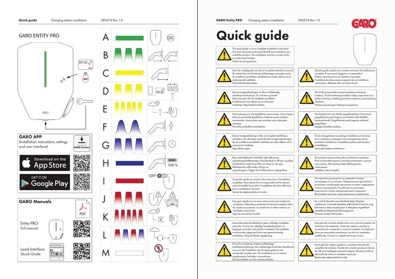
GARO ENTITY PRO User manual

1.3 GAROEntityProinstallationandoperation
GARO Entity Pro installation and
operation
Version 1.3

CONTENTS
1 Introduction................................................................................................. 5
1.1 Document description....................................................................... 5
1.2 Product description........................................................................... 5
1.2.1 Feature description................................................................ 5
1.2.2 Definitions ............................................................................. 5
1.3 Intended use..................................................................................... 6
1. Contact ............................................................................................ 6
2 Safety.......................................................................................................... 9
2.1 Safety definitions.............................................................................. 9
2.2 Safety instructions for installation ..................................................... 9
3 Product overview ...................................................................................... 11
3.1 Charging station system overview.................................................. 11
3.2 Charging station packaging overview ........................................... 12
3.3 Product variants..............................................................................13
3. Charging station overview .............................................................15
3.5 Dimensions.....................................................................................16
3.5.1 Single version installation bracket (IB) .................................16
3.5.2 Double version installation bracket (IB) ................................17
Installation ................................................................................................ 19
.1 To do before installation................................................................. 19
.2 Personnel requirements ..................................................................19
.3 Personal protective equipment........................................................19
. To do a plan for the installation ...................................................... 20
.5 To generate the installation code....................................................21
.6 To do a check of the delivery..........................................................21
.7 To ensure the necessary tools ......................................................... 21
.8 To ensure the necessary installation material.................................. 22
.9 To decide internet connection type................................................. 23
.10 To connect several charging stations............................................ 23
.10.1 Before setup ...................................................................... 23
.10.2 Simple setup scenarios ...................................................... 2
.10.3 Connection group hierarchy ............................................. 2
.11 To decide the position of the charging station .............................. 26
.12 Cable installation.........................................................................26
.12.1 To install the stickers for IT 230 V ...................................... 27
.12.2 To prepare the installation bracket for the cable
installation.........................................................................27
.12.3 To install the installation bracket to a wall ......................... 28
.12. To prepare the power cable for installation .......................29
.12.5 To connect the power cable to the terminal .......................31
.12.6 To install a second power cable (daisy-chaining
method) ............................................................................. 33
.12.7 To prepare the installation bracket with an ethernet
cable ................................................................................. 33
.12.8 To prepare the installation bracket with a second ethernet
cable ................................................................................. 3
.12.9 To connect the charging station to the Internet with
communication modem (Cat-M1/NB/GPRS) ....................35
.12.10 To install the control cable to the installation
bracket ..............................................................................35
.12.11 To change the position of the type 2 outlet or fixed
cable ................................................................................. 36
.12.12 To do a test of the power connection............................... 37
.12.13 To install a protection cover ............................................ 39

.12.1 To attach the charging unit to the installation
bracket ..............................................................................39
.12.15 To do a final functionality test of the product ................... 1
.12.16 To mount the front cover of the charging unit................... 3
.13 Dynamic Load Management (DLM).............................................. 3
.13.1 Dynamic Load Management (DLM) functionality ............... 3
.13.2 Load interface installation overview .................................. 6
.13.3 To install the load interface in an electrical cabinet ........... 50
.1 GARO Connect............................................................................56
.1 .1 The GARO Connect app ...................................................56
.1 .2 GARO Connect app process overview..............................57
.1 .3 GARO Connect app symbols overview .............................58
.1 . Owner...............................................................................61
.1 .5 Installer..............................................................................68
5 Operation.................................................................................................85
5.1 To charge an electrical vehicle .......................................................85
5.1.1 Indication light.....................................................................86
5.2 To schedule charging .....................................................................87
5.3 To stop the charging of the electrical vehicle ..................................87
6 Maintenance.............................................................................................89
6.1 To clean the charging station .........................................................89
6.2 To do a visual check of the charging station................................... 89
6.3 To do a factory reset.......................................................................89
6. To do an earth fault test ..................................................................89
6.5 To do a reset after a minor ground fault..........................................90
6.6 To do a reset of a tripped circuit breaker .......................................90
6.7 To replace a charging unit .............................................................91
6.8 PME - Protective Multiple Eathing (UK versions only) ......................92
6.9 Service ...........................................................................................92
6.10 Repair ..........................................................................................92
7 Troubleshooting ........................................................................................93
7.1 Troubleshooting .............................................................................93
8 Technical data ..........................................................................................95
8.1 Charging station technical data .....................................................95
8.2 Load interface technical data .........................................................97
8.3 Accessories ....................................................................................98
Source code....................................................................................................99
EU Declaration of conformity ........................................................................101


1 INTRODUCTION
1.1 DOCUMENT DESCRIPTION
This document describes installation and use of the
Entity Pro product, which is a member of the Entity
family. Also, the Entity Balance Load Interface
installation is described.
1.2 PRODUCT DESCRIPTION
This product is a GARO charging station for electrical
vehicles.
1.2.1 FEATURE DESCRIPTION
Entity is a series of charging stations and load interfaces
that can operate together. They are based on the
versatile open protocol OCPP, that also makes it
possible to integrate them in other systems as well as to
include third party OCPP based charging stations in the
same systems. Entity Pro is a wallbox that is easy to use,
install, and enables advanced functionality.
Configuration and operation are supported by the
GARO Connect app, available for android and Apple
devices.
1.2.2 DEFINITIONS
In the installation, setup and operation of the Entity Pro
charging stations, there are several terms and
expressions that is important to understand. Read about
the most common terms and expressions below.
Char er roup: A charger group contains several
charging stations at the same location. The charger
group manages the access rights to the charging
stations within the charger group.
Char in station: A charging station is used for
charging EVs. The charging station is connected to a
location and an owner. The charging station can be
installed and monitored through the GARO Connect
app and be part of a charger group.
Connection roup: A group of charging station(s) and
other devices that shares the same resource, such as a
fuse. The connection group is set up to protect fuses
from overload and is controlled by one device (either a
charging station or a load interface) to act as a master
device. Normally, the Connection group also defines
how the internet is connected to the units, through a
master. For more information about connection groups,
refer to .13.1 Dynamic Load Management (DLM)
functionality, page 3.
DLM system: DLM stands for Dynamic Load
Management and is a software-based solution that is
meant to manage the loads of the system of several
charging stations in an installation. DLM can be defined
as the current limiting logic applied to a connection
group.
EV: Electrical vehicle.
EV driver: An EV driver is a person that has access to
the charging station(s). The EV driver can be part of an
EV driver group and gain access to the charging station
(s) with an RFID tag or an app. The EV driver can use the
GARO Connect app to monitor charging of an EV.
EV driver roup: An EV driver group is a group of EV
drivers with the same access rights within the
organization. The access rights are managed on an
organizational level, which means that the EV driver
group can be used at several locations within the
organization.
GARO Connect app: The application from which it is
possible to install, manage and operate Entity charging
stations. For more information about the GARO
Connect application, refer to .1 GARO Connect,
page 56.
Installer: An installer is a certified installer or acts on
behalf of a certified installer. The installer is hired by the
owner to do the electrical steps of the installation of the
charging station(s) and/or a load interface. The installer
can see and change settings of the units in the location.
The installer provided access to a location with the
installation code, just like a key. The installer can during
the first setup act as a temporary owner to assist with the
installation.
Version: 1.3 5
Introduction
Load interface: The load interface connects a current
metering device to the system. This is needed when a
fuse is feeding not only charging stations and needs
monitored/dynamic overload protection (DLM).
For more information about load interface, refer to
.13.1 Dynamic Load Management (DLM) functionality,
page 3.
Location: A location is a physical address of where one
or several charging station(s) are installed. The location
is connected to an owner and can tell EV drivers where
it is possible to charge EVs. The location can contain
several charger groups. All charging stations within a
location normally uses the same grid connection point.
A location can be transferred to another owner.
Or anization: An organization contains one or several
locations. The organization shares the same owner(s)
and it is possible to create groups of EV drivers to
manage access to the charging stations.
Owner: An owner is a person who owns one or several
charging stations. This person owns the location(s) and
invites the installer to do the installation of the charging
station(s). The owner can add other owners, manage
access for EV drivers and EV driver groups, manage
charger groups and create locations, organizations and
EV driver groups. The owner can monitor and control
status of the owned charging station(s).
PME: Protective Multiple Earthing. A mandatory safety
function only applicable for the United Kingdom (UK).
Unit: A charging station or a load interface.
1.3 INTENDED USE
The product is intended for electrical vehicle charging.
Do not use the product for any other tasks.
NOTE
Follow local rules and restrictions regarding the product
and installation.
1.4 CONTACT
SE + non-listed countries:
GARO E-Mobility AB
Box 203
335 33 Gnosjö, Sweden
Telephone + 6 370 332 00
www.garo.se
FI:
GARO Finland Oy
Itälahdenkatu 18 a, FI-00210 HELSNKI, Finland
Telephone: +358 20 752 9030
E-mail: [email protected]
www.garo.fi
IR:
GARO Electric Ireland Ltd
19/307 Northwest Business Park, Blanchardstown, IE-
DUBLIN 15, Irland
Telephone: +35 31 882 00 30
E-mail: [email protected]
www.garo.ie
NO:
GARO AS
Sankt Hallvardsvei 3, NO-3 1 LIERSTRANDA,
Norway
Telephone: + 7 32 89 6 50
E-mail: [email protected]
www.garo.no,
PL:
GARO Polska Sp z.o.o.
Wislawy Szymborskiej 18, PL-70-78 SZCZECIN,
Poland
Telephone: + 8 91 881 17 70 , + 8 91 2 33 35
Email: [email protected]
www.garo.com.pl
6 Version: 1.3
Introduction


2 SAFETY
2.1 SAFETY DEFINITIONS
WARNING
Risk of personal injury or death.
CAUTION
Risk of dama e to the product or the adjacent area.
NOTE
Information that is necessary in a given situation.
2.2 SAFETY INSTRUCTIONS FOR
INSTALLATION
WARNING
Read and understand the safety warnin s below before
installation of the product.
WARNING
Do not use a dama ed char in station or a char in
station that has a red blinkin (slow 0,5 Hz) indication
li ht. If a defect is found, speak to the owner of the
char in station. The owner can be found in the GARO
Connect app. Only use char in cables with no visible
defects and intended for char in the relevant EV.
Follow all instructions for the relevant EV.
•Do not remove the screws from the sealed assembly
points on the rear side of the charging unit.
Removed screws or broken sealing will void the
warranty.
•All installation must be carried out by an authorized
installer and comply with local country installation
regulations. If any questions, please contact your
local electrical authority.
•Refer to local standards and regulations not to
exceed charging current limitations.
•Ventilation signal from EV is not supported. This
means that test of “State D” is not possible.
•Adapters for charging connectors are not allowed
to be used.
•Cord extension sets for charging cable is not
allowed to be used.
•Do not use private power generators as a power
source for charging.
•Incorrect installation and testing of the charging
station could potentially damage either the EV and/
or the charging station itself.
•Do not operate the charging station in temperatures
outside its operating range. Refer to 8.1 Charging
station technical data, page 95.
•Avoid high voltage insulation testing on connected
charging stations. If insulation testing is necessary,
first remove the charging unit from the installation
bracket.
•If the charging station is set up without any internet
connectivity, it will allow charging up to the
maximum current defined for the charging unit. The
maximum current can be up to 32 A. Default at
delivery, the maximum setting is 16 A. This means
that an unconfigured charging station will function
without any internet connection, up to 16 A.
•Do not use the product if any parts are damaged.
•Do not connect an EV if the indication light is
blinking a slowly in red (0,5 Hz).
Version: 1.3 9
Safety


3 PRODUCT OVERVIEW
3.1 CHARGING STATION SYSTEM OVERVIEW
A. Installation bracket. The installation bracket is
available as single and double (side by side).
B. Charging unit. The charging unit is available in
several versions. Refer to 3.3 Product variants, page
13. The fixed cable (B1) or Type 2 outlet (B2) can be
positioned on either side of the charging unit.
C. Front cover for charging units without an MID
certified, visible energy meter. The front cover is
available in several colors.
D. Front cover for charging units with an MID certified,
visible energy meter. The front cover is available in
several colors.
E. Protection cover. The protection cover is an
accessory that is used for a prepared installation
without an attached charging unit.
Garo offers various installation accessories. Both as a
complete charging station or as individual system
components.
A B
B1 B2
C
D
E
Version: 1.3 11
Product overview

3.2 CHARGING STATION PACKAGING OVERVIEW
Char in station (CS)
A charging station is a complete kit, packed in a box. It
contains all parts required for EV charging. The product
is available in several versions.
Char in unit (CU)
The charging unit is the active part of the charging
station. To be plugged into the installation bracket. The
charging unit is available in several versions.
Front cover
Front cover for charging units with or without an MID
certified, visible energy meter. The front cover is
available in several colors.
Installation bracket — sin le (IB)
The installation bracket is where the physical installation
is done. It contains a permanent RFID tag with the
identity of the physical charging station. The installation
bracket is available as single and double.
The protection cover covers the installation in the
installation bracket. The protection cover is an
accessory that us used for a prepared installation
without an attached charging unit.
Installation bracket - double (IB)Installation bracket - single (IB)
Charging Unit (CU) Front cover
Charging tation (C)
12 Version: 1.3
Product overview

A. With Type 2 outlet, with internal energy meter (not
visible on the front cover).
B. With Type 2 outlet, with MID certified, visible
energy meter.
C. With Type 2 cable, with internal energy meter (not
visible on the front cover).
D. With Type 2 cable, with MID certified, visible
energy meter.
The product concept can for special high volume orders
be customized to with or without the features listed
below:
•Type 2 outlet or fixed cable.
•Long fixed cable (8 m) or normal fixed cable (5 m).
•32 A or 20 A fixed cable.
•Three-phase or one-phase.
•With or without phase balancing.
•With or without mobile communication modem
(Cat-M1/NB/GPRS).
•With or without ISO 15118 HW support.
•With or without SIM, supplied from GARO.
•With or without PME protection (UK only).
1 Version: 1.3
Product overview

3.4 CHARGING STATION OVERVIEW
A. Power connection terminal (in and out).
B. Bracket terminal connector.
C. Charging unit connector.
D. Installation bracket QR label.
E. Ethernet cable inlet.
F. Control cable inlet.
G. Visible MID energy meter (optional).
H. All-pole circuit breaker, manual reset.
I. PE disconnection relay (PME protection variant only)
(for UK only).
J. 2 port Ethernet switch RJ 5.
K. Control cable port and connector.
L. SIM card slot (size 3 FF/Micro).
M. Flat adapter cover.1
R
D
B
E
A
F
T
O
H
I
R
D
N
CK
L
J
M
G
P
Q
Version: 1.3 15
Product overview
1. The fixed cable variant of the charging unit has the fixed cable placed here.

N. Type 2 outlet.2
O. Front cover lock.
P. Indication light.
Q. Optional ID-label placement after installation.
R. Label, load interface type.
S. Sealing label.
T. RFID reader area.
3.5 DIMENSIONS
Dimensions for bracket hole positions:
3.5.1 SINGLE VERSION INSTALLATION BRACKET
(IB)
Bracket and hole dimensions:
240 mm150 mm
340 mm
480 mm
150 mm
340 mm
240
160
119
174
71
333
Ø35
Knockout
Ø6
120
16 Version: 1.3
Product overview
2. The fixed cable variant of the charging unit has the cable parking placed here.

Bracket and knockout dimensions:
3.5.2 DOUBLE VERSION INSTALLATION BRACKET
(IB)
Bracket and hole dimensions:
Bracket and knockout dimensions:
240
160
119
174
120
333
Ø6
Ø6
Ø6
71
55
104
Ø32
KnockoutØ32
Knockout
Ø32
Knockout
419
485
245
333
160
119
Ø6 Ø6
Ø6Ø6
Ø6Ø6
71
245
141104 104
71
55
Ø32
Knockout
Ø32
KnockoutØ32
Knockout
Ø32
Knockout
Ø32
Knockout
Ø32
Knockout
Ø32
Knockout
Version: 1.3 17
Product overview


4 INSTALLATION
4.1 TO DO BEFORE INSTALLATION
•Make sure that the correct training is provided to do
the installation.
4.2 PERSONNEL REQUIREMENTS
•To safely and correctly install the charging station,
only a certified installer or somebody who acts on
behalf of a certified installer may perform the
installation. Comply with local requirements.
•Only a technically skilled person with the necessary
knowledge of the GARO Entity charging station
may replace the charging unit.
4.3 PERSONAL PROTECTIVE EQUIPMENT
WARNING
Make sure that the correct personal protective
equipment for the installation is available. Adapt the
personal protective equipment to suit the installation
location. Comply with local requirements. Note that
more personal protective equipment can be necessary.
•Protective shoes for electricians.
•Protective gloves.
•Protective goggles.
•Protective helmet.
•Hearing protection.
•High visibility clothing.
Version: 1.3 19
Installation

4.4 TO DO A PLAN FOR THE INSTALLATION
•Prepare the installation location according to the
steps that are shown in the illustration.
A. Decide where to put the charging station(s).
Make sure that the location is suitable due to
weather conditions and preparation for future
expansion.
NOTE
Charging station(s) can be attached to a wall, a stand
or a pole. Installation accessories are available at
GARO.
B. Decide on how to define the location and
naming of the charging station(s).
C. Decide on access control for EV drivers. It is
possible to control access with the GARO
Connect app or RFID tags where controlled
authorization is necessary. Those can also be
combined in a schedule.
NOTE
RFID tags are available as accessories at GARO.
D. Plan the power supply and current availability
on all levels of the installation. Plan for the DLM
(dynamic load management) system setup. Refer
to .13.1 Dynamic Load Management (DLM)
functionality, page 3 .
E. If several charging stations are used, decide
which unit (charging station or load interface)
that should act as master unit. This can be
affected by a DLM setup.
F. Decide the internet connection type for the
master unit in the connection group (the
charging station or a load interface unit(s)
managing this role).
G. Decide the connection type between all
charging stations, if applicable. If large
connection groups are needed for DLM the
connection structure needs to be divided into a
group structure, with max. 32 units in each
group preferably following the DLM structure,
and when a mesh Wifi grid is required to be set
up.
H. Make sure that the necessary tools and testing
instruments for installation are available.
I. Make sure that the correct installation material is
available.
J. Decide if the installer or owner should prepare
the installation in the GARO Connect app. Refer
to .1 GARO Connect, page 56.
JI K
FE G
BA C
H
D
L
NM
WWW
20 Version: 1.3
Installation
Other manuals for ENTITY PRO
3
Table of contents
Other GARO Automobile Batteries Charger manuals
Popular Automobile Batteries Charger manuals by other brands

Myenergi
Myenergi eddi 16A1P01H installation manual

Free2Move eSolutions
Free2Move eSolutions eProWallbox Move user manual

EM2GO
EM2GO EM016CC user manual

Taramps Electronics
Taramps Electronics PRO CHARGER 30A instruction manual

Charge Amps
Charge Amps Ray Type 2 product manual

ULTIMATE SPEED
ULTIMATE SPEED ULGD 3.8 A1 Operation and safety notes