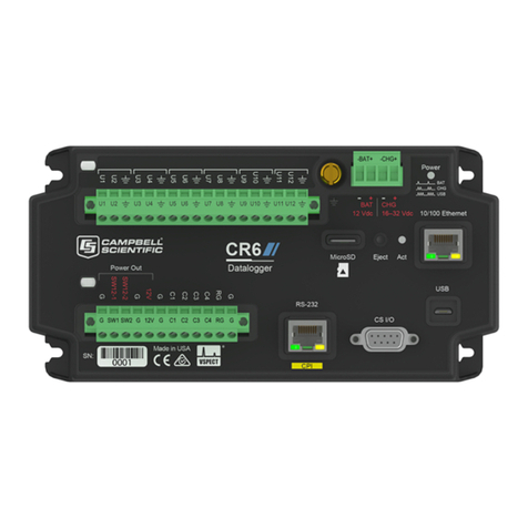
Circutor PV-Monitor-M User manual

INSTRUCTION MANUAL
Photovoltaic energy monitoring datalogger
PV-Monitor-M
(M135B01-03-19A)

2
PV-Monitor-M
Instruction Manual

3
Instruction Manual
PV-Monitor-M
SAFETY PRECAUTIONS
DANGER
Warns of a risk, which could result in personal injury or material damage.
ATTENTION
Indicatesthatspecialattentionshouldbepaidtoaspecicpoint.
Follow the warnings described in this manual with the symbols shown below.
If you must handle the unit for its installation, start-up or maintenance, the following
should be taken into consideration:
Incorrect handling or installation of the unit may result in injury to personnel as well as damage
to the unit. In particular, handling with voltages applied may result in electric shock, which may
cause death or serious injury to personnel. Defective installation or maintenance may also
leadtotheriskofre.
Read the manual carefully prior to connecting the unit. Follow all installation and maintenance
instructions throughout the unit’s working life. Pay special attention to the installation stan-
dards of the National Electrical Code.
Refer to the instruction manual before using the unit
In this manual, if the instructions marked with this symbol are not respected or carried out correctly, it can
result in injury or damage to the unit and /or installations.
CIRCUTOR,SAreservestherighttomodifyfeaturesortheproductmanualwithoutpriornotication.
DISCLAIMER
CIRCUTOR, SAreservestherighttomakemodicationstothedeviceortheunitspecica-
tions set out in this instruction manual without prior notice.
CIRCUTOR, SA on its web site, supplies its customers with the latest versions of the device
specicationsandthemostupdatedmanuals.
www.circutor.com
CIRCUTOR, recommends using the original cables and accessories that are
supplied with the device.

4
PV-Monitor-M
Instruction Manual
CONTENTS
SAFETY PRECAUTIONS ���������������������������������������������������������������������������������������������������������������������������������������3
DISCLAIMER ����������������������������������������������������������������������������������������������������������������������������������������������������������3
CONTENTS�������������������������������������������������������������������������������������������������������������������������������������������������������������4
REVISION LOG�������������������������������������������������������������������������������������������������������������������������������������������������������5
1�- VERIFICATION UPON RECEPTION�����������������������������������������������������������������������������������������������������������������6
2�- INTRODUCTION������������������������������������������������������������������������������������������������������������������������������������������������6
3�- INSTALLATION OF THE DEVICE ���������������������������������������������������������������������������������������������������������������������8
3�1�- PREVIOUS RECOMMENDATIONS ����������������������������������������������������������������������������������������������������������8
3�2�- INSTALLATION �����������������������������������������������������������������������������������������������������������������������������������������9
3�3�- DEVICE TERMINALS��������������������������������������������������������������������������������������������������������������������������������9
3�4�- CONNECTION DIAGRAMS ��������������������������������������������������������������������������������������������������������������������10
4�- OPERATION ��������������������������������������������������������������������������������������������������������������������������������������������������� 11
4�1�- LED INDICATORS ����������������������������������������������������������������������������������������������������������������������������������� 11
4�2�- DISPLAY ������������������������������������������������������������������������������������������������������������������������������������������������� 11
4�3�- KEYS ������������������������������������������������������������������������������������������������������������������������������������������������������ 11
5�- START-UP �������������������������������������������������������������������������������������������������������������������������������������������������������12
5�1�- STEP 1: HARDWARE INSTALLATION���������������������������������������������������������������������������������������������������12
5�2�- STEP 2: CONFIGURATION OF THE CDP-0�������������������������������������������������������������������������������������������13
5�3�- STEP 3: CONFIGURATION OF THE PV-Monitor-M �����������������������������������������������������������������������������13
5�4�- STEP 4: CONFIGURATION OF THE ROUTER ��������������������������������������������������������������������������������������14
5�5�- STEP 5: CONFIGURATION OF THE RS-485 BUS���������������������������������������������������������������������������������16
5�6�- STEP 6: CONFIGURATION OF THE INSTALLATION PARAMETERS��������������������������������������������������16
6�- PV-MONITOR-M APPLICATION ���������������������������������������������������������������������������������������������������������������������17
6�1�- MAIN SCREEN ����������������������������������������������������������������������������������������������������������������������������������������17
6�1�1� ENERGY BALANCE���������������������������������������������������������������������������������������������������������������������������19
6�1�2� SOLAR FRACTION ����������������������������������������������������������������������������������������������������������������������������21
6�1�3� UTILIZATION RATE AND ALARMS���������������������������������������������������������������������������������������������������21
6�1�4� MONTHLY RESUME���������������������������������������������������������������������������������������������������������������������������22
6�1�5� SENSORS�������������������������������������������������������������������������������������������������������������������������������������������23
6�2�- STRING MONITORING SCREEN �����������������������������������������������������������������������������������������������������������24
6�3�- SETUP SCREEN �������������������������������������������������������������������������������������������������������������������������������������25
6�4�- CONFIGURATION OF ALARMS�������������������������������������������������������������������������������������������������������������26
6�4�1� CONFIGURATION OF THE ALARM WARNINGS SENT VIA E-MAIL�����������������������������������������������27
6�4�2� CONFIGURATION OF ALARMS ��������������������������������������������������������������������������������������������������������27
7�- TECHNICAL FEATURES ��������������������������������������������������������������������������������������������������������������������������������28
8�- MAINTENANCE AND TECHNICAL SERVICE������������������������������������������������������������������������������������������������30
9�- GUARANTEE���������������������������������������������������������������������������������������������������������������������������������������������������30
10�- CE CERTIFICATE������������������������������������������������������������������������������������������������������������������������������������������31

5
Instruction Manual
PV-Monitor-M
REVISION LOG
Table 1: Revision log�
Date Revision Description
11/16 M135B01-03-16A Initial Version
01/17 M135B01-03-17A Changes in the following sections:
6.- 6.1. - 6.1.1. - 6.1.3. - 6.1.4 - 6.2. -6.3.
12/19 M135B01-03-19A
Changes in the following sections:
1.- 2. - 3.3. - 3.4. - 5.1. - 5.4. - 5.5. - 6.1. - 6.1.1. - 6.1.2. -
6.1.3. - 6.1.4. - 6.1.5. - 6.2. - 6.3.
Note: Images of the devices are for illustrative purposes only and may differ from the actual
device.

6
PV-Monitor-M
Instruction Manual
1�- VERIFICATION UPON RECEPTION
Check the following points when you receive the device:
a)Thedevicemeetsthespecicationsdescribedinyourorder.
b) The device has not suffered any damage during transport.
c) Perform an external visual inspection of the device prior to switching it on.
d) Check that it has been delivered with the following:
- Installation guide.
If any problem is noticed upon reception, immediately contact the transport
company and/or CIRCUTOR's after-sales service.
2�- INTRODUCTION
The PV-Monitor-M is an energy manager that has been designed to monitor instantaneous
self-consumption photovoltaic energy installations (with or without injection into the grid). It
features a datalogger and web server with PowerStudio Embedded and a SCADA application
for this purpose.
This device provides real-time information about the installation performance,photovoltaic
energyproductionlevels,theconsumptionofabuilding,home,ofce,etc.,aswellasstoring
historical data to perform periodic analyses.
The SCADA electric energy management application can provide real-time information about
the photovoltaic energy production levels, electricity savings and the load consumption of elec-
tricityofabuilding,home,ofce,etc.ItreceivestheinternalvariablesofaCDP-0 and does not
dependonthecongurationofthephotovoltaicenergyplant(installedpower,inverterdevice,
single or three-phase network and measuring points).
The device features:
- An Ethernet Port.
- Indicator LEDs.
-Display with two 20-character rows.
- 4 keys
- RS-485 Communications.

7
Instruction Manual
PV-Monitor-M
The PV-Monitor-M requires the use of the following devices to achieve the correct electric en-
ergy management of an installation:
Table 2:List of devices required for the PV-Monitor-M system�
Code Name Description
E51001 CDP-0 Dynamic power controller
EX0056 RT-N150 Router
E80005 TRH16-RS485 Multi-channel DC voltage and current analyzer for photovoltaic strings
M60413 PSC-12 Voltage source for MET probes
M80010 M/TR-25 x2 Measuring module for 2 current circuits
M80011 M/TR-25 x4 Measuring module for 4 current circuits
EX0095 MET-485 Radiation probe, ambient temperature and PV modules temperature
The functional features of the SCADA application are:
Display of the parameters measured and/or calculated by the devices in real time on the
SCADA screens
Setup of general system alarms to warn about the anomalous operation of a photovoltaic
energy installation.

8
PV-Monitor-M
Instruction Manual
3�- INSTALLATION OF THE DEVICE
3.1.- PREVIOUS RECOMMENDATIONS
In order to use the device safely, it is critical that individuals who handle it follow
the safety measures set out in the standards of the country where it is being used,
use the personal protective equipment necessary, and pay attention to the vari-
ous warnings indicated in this instruction manual.
The PV-Monitor-Mdevicemustbeinstalledbyauthorisedandqualiedstaff.
The power supply plug must be disconnected and measuring systems switched off before han-
dling, altering the connections or replacing the device. It is dangerous to handle the device
while it is powered.
Also, it is essential to keep the cables in perfect condition to avoid accidents, personal injury
and damage to installations.
The manufacturer of the device is not responsible for any damage resulting from failure by the
user or installer to observe the warnings and/or recommendations set out in this manual, nor for
damage resulting from the use of non-original products or accessories or those made by other
manufacturers.
If an anomaly or malfunction is detected in the device, do not use the device to take any meas-
urements.
Inspect the work area before taking any measurements. Do not take measurements in danger-
ous areas or where there is a risk of explosion.
Disconnect the device from the power supply (device and measuring system
power supply) before maintaining, repairing or handling the device's connections.
Please contact the after-sales service if you suspect that there is an operational
fault in the device.

9
Instruction Manual
PV-Monitor-M
3.2.- INSTALLATION
The PV-Monitor-M hasbeendesignedformountingonaDINrail,withstandardxingpointsso
that it can be mounted on the rail.
Terminals, opening roofs or removing elements can expose parts that are haz-
ardous to the touch while the device is powered. Do not use the device until it is
fully installed.
3.3.- DEVICE TERMINALS
Table 3:List of terminals of the PV-Monitor-M�
Terminals
1: Ethernet, Ethernet connection 5: L, Auxiliary power supply
2: A, RS-485 connection 6: N, Auxiliary power supply
3: S, RS-485 connection 7: Ground connection
4: B, RS-485 connection
A S B L N
Ethernet RS-485
12 3 45 6 7
Figure 1:PV-Monitor-M terminals�

10
PV-Monitor-M
Instruction Manual
3.4.- CONNECTION DIAGRAMS
L N
Ethernet
ON
ACT
COM 1
COM 2
ALARM
OK
LINK
+ 12 V -
DC Power
Supply
C4 3 2 1
INPUTS
Ethernet
PV-Monitor-M CDP-0
Ethernet
Ethernet
Vd2 Vd1
Vd(1000Vdc)
A(+) S(GND) B(-)
COM1 RS485/S
A(+) S(GND) B(-)
COM2 RS485/M
AC POWER
SUPPLY 230 Vac
AC POWER
SUPPLY 24 Vdc
Pt 100/1000 ANALOG DIGITAL
|1 |2 |3 COM
1 2
22 23 24
3 4 5 6 7 8 9 10 11 12
16 17 18 19 20 21
13 14 15
A S B
RS-485
RS-485
1 2 6
AB
+ -
MET-485
TRH16-RS485
M/TR-25
M/TR-25
9 10
S
TRH16-RS485-25A
Router CIRCUTOR
Power
Supply
Power
Supply ~
Power
Supply
Power
Supply
Figure 2: Connection diagram of the PV-Monitor-M system�

11
Instruction Manual
PV-Monitor-M
4�- OPERATION
4.1.- LED INDICATORS
The PV-Monitor-M features 2 indicator LEDs:
SLAVES
CPU
LEDs
Keys
Figure 3: LEDs of the PV-Monitor-M
Table 4:List of LEDs of the PV-Monitor-M�
LEDs
CPU Blinking light: Indicates that the device is operating correctly.
Power on: The device is not functioning properly.
SLAVE Off: All connected devices are communicating correctly.
Power on: One or more devices are not communicating.
4.2.- DISPLAY
ThedevicefeaturesabacklitLCDdisplaythatcanbeusedtocongurethenetworkparame-
ters.
The main screen of the display shows the date and time of the device.
- -
Figure 4: Main screen of the PV-Monitor-M�
4.3.- KEYS
The PV-Monitor-M features 4 keys, Figure 3,tocongurethenetworkparameters.

12
PV-Monitor-M
Instruction Manual
5�- START-UP
Follow these steps to start-up the PV-Monitor-M:
5.1.- STEP 1: HARDWARE INSTALLATION
Install all system devices. Follow the instructions of the installation manual of each device and
the connection diagram in section “3.4.- CONNECTION DIAGRAMS”
The PV-Monitor-M system is composed of the following elements:
Dynamic power controller, CDP-0.
PV-Monitor-M
Router, to create the internal communications network.
TRH16, multi-channel DC voltage and current analyzer.
MET-485, Radiation probe, ambient temperature and PV modules temperature.
M/TR-25, measurement module for current circuits.
PV-Monitor-M
CDP
TRH16 M/TR-25
Router customer
Router CIRCUTOR
MET-485 sensor
Figure 5: PV-Monitor-M System�

13
Instruction Manual
PV-Monitor-M
5.2.- STEP 2: CONFIGURATION OF THE CDP-0
CongurethenetworkparametersoftheCDP-0, so it can communicate with the PV-Monitor-M:
IP: 192�168�0�3,
MASK: 255�255�255�0
Gateway (GW): 192�168�0�1
Follow the steps in the instruction manual of the CDP-0 (M98250001-01-xxx), section “5.2.
NETWORK MENU”.
Check that the CDP-0 has been correctly installed with the validation of its measuring points
(PV energy generation, consumption and network). In the event of anomalies, report the results
of the inspection to the end customer / installer.
5.3.- STEP 3: CONFIGURATION OF THE PV-Monitor-M
FollowthesestepstocongurethenetworkparametersofthePV-Monitor-M:
1�-Pressthe►+▲+▼keyssimultaneouslyformorethantwoseconds.Awarningmessageis
displayed
Note: After entering the setup menu, if no key is pressed for 30 seconds, the device will exit
the setup menu. If any change has been made to the setup, it will not be applied unless the last
menu option is accessed (save changes).
2�- Pressthe▼arrowtwice.TheDHCPoptionwillbesettoYES.Usingthe◄or►keys,the
congurationcanbechangedtoYESorNO.LeavethisparametersettoNO�
3�- Pressthe▼keytwicetoaccessthecongurationoftheIPaddress.
4�-Pressthe►keyoncetoactivatetheeditmode.Acursorwillappearundertherstdigitof
the IP address
Pressthe▲or▼keystoincreaseordecreasethevalueofthedigitbeingedited.
Pressthe◄or►keytomovetheeditcursorhorizontallyandselectthenextorpreviousdigit
to be edited.
Repeat the steps to complete the IP address: 192�168�0�2,
5�-WiththeIPaddresscompleteandtheeditcursoronthelastdigit,pressthe►key;thecur-
sor will disappear.
6�-Pressthe▼keytomovetothenextparametertobecongured,thesubnetmaskorNET-
MASK.
Pressthe►keytoincreasethesubnetmaskblocks.
Mask: 255�255�255�0,
7�-Pressthe▼keytomovetothenextparametertobecongured,theGateway.
Gateway: 192�168�0�1
Use the ▲,▼and►keystomodifythevalue.

14
PV-Monitor-M
Instruction Manual
5.4.- STEP 4: CONFIGURATION OF THE ROUTER
Congurethenetworkparametersoftheroutersuppliedwiththedevice.Todoso:
1�- Connect an Ethernet cable between the Client router and router of the installation (yellow
RJ45).
2�- Connect an Ethernet cable between the computer and router of the installation.
3�- Connect an Ethernet cable between the PV-Monitor-M and router of the installation.
4�- Connect an Ethernet cable between the CDP-0 and router of the installation.
PV-Monitor-M
CDP-0
Router Customer
Computer
Figure 6: Connections of the router of the installation�
5�- Access the router of the installation, IP: 192�168�0�1.
A screen will be displayed, where you must enter the access password:
User: Admin,
Password: leave blank,
Note: Check that the CDP and PV-Monitor-M are in the same IP range.
6�- In the main screen of the router, Figure 7, select Advanced network parameters.

15
Instruction Manual
PV-Monitor-M
Figure 7: Main screen of the router�
7�- Enter the Advanced menu and, in the Port Forwarding rules section, route the PV-Moni-
tor-M and CDP-0 as indicated in Figure 8.
Figure 8: Router conguration screen
8�- Savetherouterconguration.
9�- Remove the Ethernet cable connected between the computer and the router.
10�- Open a browser in a computer connected to the network of the PV-Monitor-M and CDP-0
and enter:
http://IP_ROUTER:8080/html5/index�html to access the web server of the PV-Monitor-M
http://IP_ROUTER:8081 to access the web server of the CDP-0
http://IP_ROUTER:8081/setup toaccessthecongurationwebserveroftheCDP
Where IP_ROUTER is the external IP address of the router, as shown in Figure 7.

16
PV-Monitor-M
Instruction Manual
5.5.- STEP 5: CONFIGURATION OF THE RS-485 BUS
The PV-Monitor-M model communicates with the TRH16 and with the MET-485 sensor via the
RS-485 bus.
Thefollowingmustbeconguredforbothdevicestocommunicate:
A�- TRH16
Peripheral number: 2
Selector Position: HI = 0, LOW=2
Transmission speed: 38400 bauds
Position of the dips: Dip1: ON(up), Dip2: OFF (down)
B�- MET-485 sensor
Theparametersoftheprobehavealreadybeencongured,soitsinstallationisplug&play.You
only need to power the probe and connect the RS-485 bus.
Note: Please refer to the instruction manuals if you have any doubts in relation to the congu-
ration of the devices.
5.6.- STEP 6: CONFIGURATION OF THE INSTALLATION PARAMETERS
Access the PV-Monitor-M applicationandcongure:
the parameters of the PV installation, see “6�2�- SETUP SCREEN”�
the alarm parameters, see “6�4�- CONFIGURATION OF THE ALARMS”�

17
Instruction Manual
PV-Monitor-M
6�- PV-Monitor-M APPLICATION
The PV-Monitor-M application can:
Monitor and control all devices in the installation in real time.
Calculate the instantaneous energy balance of consumption compared to PV energy
generation.
Calculate the % self-consumption of the current month (solar fraction).
CongurethemonthlyPVenergyproductiontargets.
Congurealarmstowarnaboutanomalousoperation:
- Device communication errors,
- Detection of reverse current,
- Modulation of the inverter power,
- Low solar fraction.
Receive alarm warnings via e-mail.
6.1.- MAIN SCREEN
Figure 9 show the main screen of the SCADA PV-Monitor-M application. There screen is used
as the control panel to monitor and control the photovoltaic energy installation, providing all
useful information required to guarantee its top performance.
Figure 9: Main screen PV-Monitor-M�

18
PV-Monitor-M
Instruction Manual
The screen is divided into two areas, Figure 13:
Top area
Central area
Figure 10: Areas on the main screen�
Top area, where you can:
- Access the String monitoring screen (See “6.2.- STRING MONITORING SCREEN” ).
- Access the setup screen (See “6�3�- SETUP SCREEN”).
Central area, which displays all general data of the installation.

19
Instruction Manual
PV-Monitor-M
6�1�1� ENERGY BALANCE
The Energy balance widget displays all general data of the installation, Figure 11
Figure 11:Energy balance widget�
The Grid section shows:
The instantaneous network consumption, in kW.
The network consumption of the current month, in kWh.
The PV Generatos section shows:
The target PV production of the current month, in kWh.
The installed PV power, in kWp.
The instantaneous PV production, in kW.
The PV production of the current month, in kWh.
The graphical representation of the degree of completion of the target PV production�
When you click on the left mouse button: The daily graphical representation of the PV
production, network consumption and building consumption values, Figure 12�

20
PV-Monitor-M
Instruction Manual
Figure 12:Daily graphical representation of the PV production, network consumption and building consumption
(kW)�
The following is displayed in the Building consumption section:
The instantaneous consumption, in kW.
The consumption of the current month, in kWh.
The graphical representation of the % instantaneous network consumption and of
the instantaneous PV energy production�
When you click on the left mouse button: The monthly graphical representation of the
PV production, network consumption and building consumption values. The evo-
lution of the Solar Fraction as a % throughout the month as compared to the annual
average target is also shown,Figure 13�
Figure 13:Monthly graphical representation of the PV production, network consumption and building consumption
(kWh)�
Table of contents
