CIS enLOGIC EA9502 User manual

Electronic Rack
User Manual
Electronic Rack
eHandle
User Manual

Contents
1: Introduction
................................
2: eHandle Overview
................................
2.1 Specifications
and Functions
2.2 eHandle Wiring Diagram
2.3 eHandle
General Features
2.3.1 eHandle
Compatibility
2.3.2 eHandle
Lock Function
2.3.3 Integrated LED Indicators
3: eHandle
Installation Instruction
3.1 Types of SmartZone G5
eHandle
3.2 eHandle
Included Installation Parts
3.3 eHandle
Lock Mounting Option for Front and Rear Door
4: eHandle
WEB Configuration
4.1 ID User Authorization/Add Card
4.2 Rack Access Settings
................................
4.3 eHandle Settings
................................
4.4 Keypad Settings
................................
4.5 Remote Control
................................
4.6 Beacon Settings
................................
4.7 Status LED Settings
................................
5: FCC Statement
................................
................................
................................
................................
................................
and Functions
................................................................
................................
................................................................
................................
General Features
................................................................
................................
Compatibility
................................................................
................................
Lock Function
................................................................
................................
2.3.3 Integrated LED Indicators
................................
................................
Installation Instruction
................................
eHandle
................................
................................
Included Installation Parts
................................
................................
Lock Mounting Option for Front and Rear Door
................................
WEB Configuration
................................
.....................
4.1 ID User Authorization/Add Card
................................
................................
................................
................................
................................
................................
................................
................................
................................
................................
................................
................................
................................
................................
................................
................................
................................
................................
................................
................................
................................
................................
................................
................ 3
................................
...... 4
................................
.... 4
................................
.......... 5
................................
........ 7
................................
.... 7
................................
... 9
................................
............................. 10
................................
............... 12
................................
............................ 12
................................
........................ 13
................................
...................... 14
.....................
15
................................
............................. 15
................................
............... 17
................................
..................... 17
................................
...................... 18
................................
...................... 19
................................
...................... 22
................................
................. 23
................................
.......... 25
1: Introduction
1.1 The SmartZone G5
eHandle
electronic locking options
for Panduit Standard Cabinets monitored and controlled through the Panduit
SmartZone G5 PDU.
1.2
There are five configuration options available
SKU No
P
EA9502
EH01
EA9500
EH02
EA9503
EH03
EA9501
EH04
1.3 The eHandle a
ccessories and harnesses supported by the SmartZone G5
P/N
ACF10
eHandle
ACF11
eHandle
ACF20
eHandle
ACF30
eHandle
ACF31
eHandle
ACF32
eHandle
ACF33
eHandle
ACF34
eHandle
ACF35
eHandle
ACF36
eHandle
ACF37
eHandle
ACF38
eHandle
ACF39
eHandle
ACF40
eHandle
ACF41
eHandle
1.
The tumbler locking mechanism should only operate when combined with the
corresponding key for the same option group.
2.
The Standard Tumbler should only operate when combined with the Standard Key.
eHandle
products are intended to provide access control
solution
for Panduit Standard Cabinets monitored and controlled through the Panduit
There are five configuration options available
for the eHandle
family products as the following:
P
/N Description
EH01
eHandle
RFID (125kHz / 13.56MHz) with integral humidity sensor
EH02
eHandle
RFID (125kHz / 13.56MHz) and Keypad with integral
humidity sensor
EH03
eHandle
No Card Reader with integral humidity senso
EH04
eHandle No Card Reader with
Keypad
sensor
ccessories and harnesses supported by the SmartZone G5
eHandle
Description
eHandle
(1) Temperature and (1) Door Sensor
eHandle
(3) Temperature Sensors and (1)
Door Sensor
eHandle
to Panduit G5 PDU Harness
eHandle
Standard Key (10 pack)
eHandle
Alternate Key Option 1 (10 pack)
eHandle
Alternate Key Option 2 (10 pack)
eHandle
Alternate Key Option 3 (10 pack)
eHandle
Alternate Key Option 4 (10 pack)
eHandle
Alternate Key Option 5 (10 pack)
eHandle
Standard Tumbler (10 pack)
eHandle
Alternate Tumbler Option 1 (10 pack)
eHandle
Alternate Tumbler Option 2 (10 pack)
eHandle
Alternate Tumbler Option 3 (10 pack)
eHandle
Alternate Tumbler Option 4 (10 pack)
eHandle
Alternate Tumbler Option 5 (10 pack)
The tumbler locking mechanism should only operate when combined with the
corresponding key for the same option group.
The Standard Tumbler should only operate when combined with the Standard Key.
3
solution
s with a series of
for Panduit Standard Cabinets monitored and controlled through the Panduit
family products as the following:
RFID (125kHz / 13.56MHz) with integral humidity sensor
RFID (125kHz / 13.56MHz) and Keypad with integral
No Card Reader with integral humidity senso
r
Keypad
with integral humidity
eHandle
products are listed below:
Door Sensor
The tumbler locking mechanism should only operate when combined with the
The Standard Tumbler should only operate when combined with the Standard Key.
4
2: eHandle
Overview
2.1 Specifications and F
unctions
Specifications
Power supply requirement:
Handles
shall receive power via RJ45 connector through custom patch cable conn
distribution unit
‐ eHandle
shall be powered by 5VDC power source
‐ 5VDC tolerance: ±10%
‐ Standby current: 50mA Max
‐
Typical operating current shall be less than 500mA @ 5VDC
‐
Maximum peak/stall operating current shall be less than 1,150mA @ 5VDC
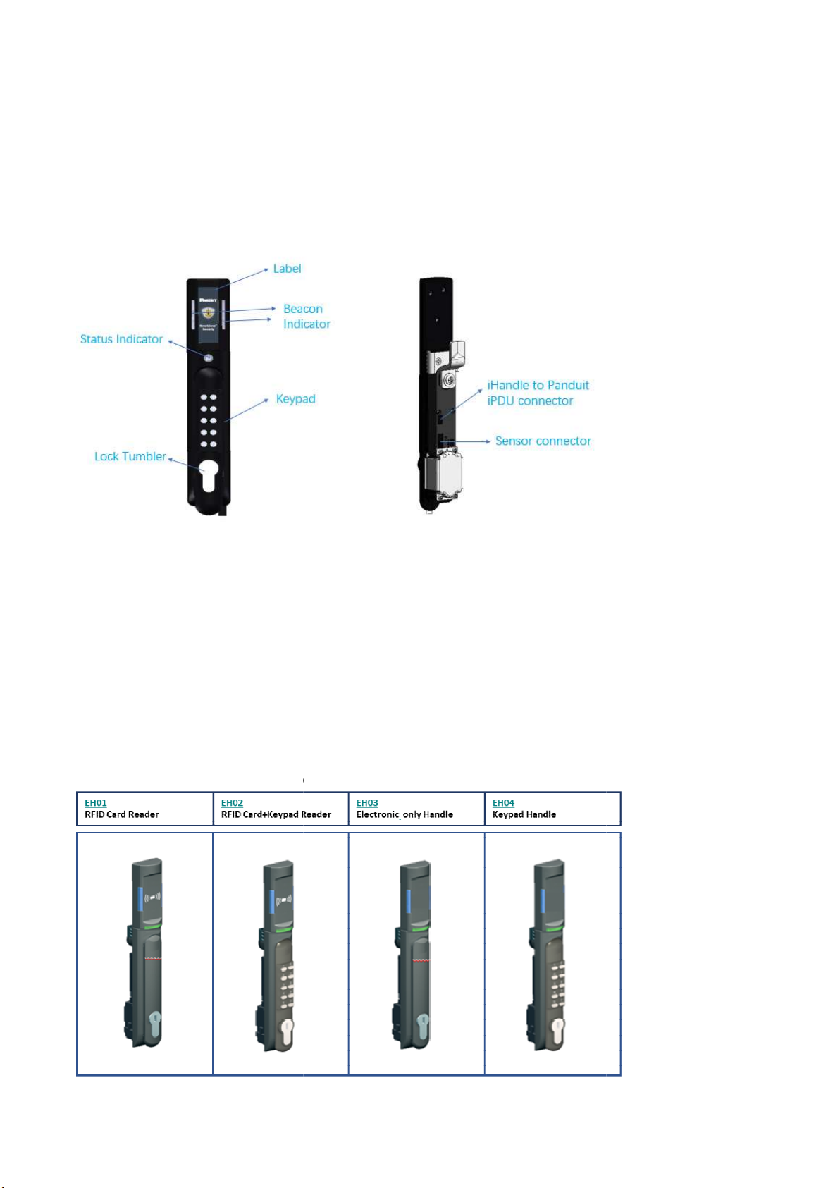
Four types of Handle
s are listed below.
Electronic Rack
eHandle
Overview
unctions
shall receive power via RJ45 connector through custom patch cable conn
ected to CIS manufactured power
shall be powered by 5VDC power source
Typical operating current shall be less than 500mA @ 5VDC
Maximum peak/stall operating current shall be less than 1,150mA @ 5VDC
s are listed below.
eHandle
User Manual
ected to CIS manufactured power

Functions of each type of Handles
P/N eHandle Types
EH01 RFID Card Reader ‐
‐
‐
EH02 RFID Card+Keypad
Reader
‐
‐
‐
‐
EH03 Electronic only
eHandle
‐
‐
‐
EH04 Keypad only
eHandle
‐
‐
‐
‐
‐
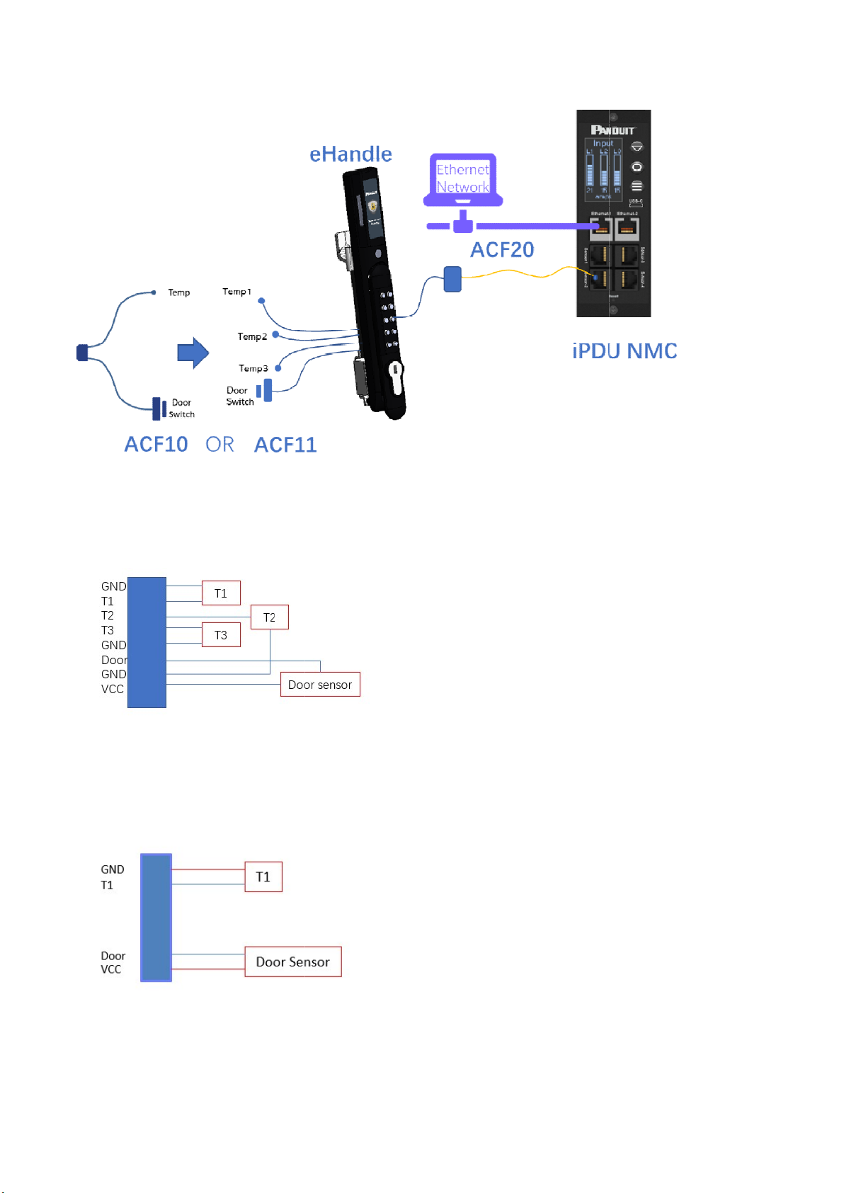
2.2 eHandle
Wiring Diagram
The wiring diagram below provides a visual illustration of the physical connections and physical layout of a
typical electronic rack eHandle
system, demonstrating the interconnections between a
eHandle
, a Panduit PDU, and relative sensors.
Description
eHandle RFID (125kHz /13.56MHz)
with integral humidity sensor
Support Single factor RFID card authentication
Remote lock/unlock capability
eHandle RFID (125kHz /
13.56MHz) and Keypad with
sensor
Support Dual Authentication
Remote lock/unlock capability
Need to provide an option in firmware to hide the pin with * when pin is
typed. This hidden pin mode can be enabled and disabled in firmware.
eHandle No Card Reader with in
tegral humidity sensor
Remote lock/unlock capability
RF support to be disabled in factory firmware mode.
eHandle No Card Reader and Keypad with
integral humidity sensor
Support User pin authentication
Physical key override
Remote lock/unlock capability
RF support to be disabled in factory firmware mode.
Wiring Diagram
The wiring diagram below provides a visual illustration of the physical connections and physical layout of a
system, demonstrating the interconnections between a
, a Panduit PDU, and relative sensors.
5
with integral humidity sensor
13.56MHz) and Keypad with
integral humidity
Need to provide an option in firmware to hide the pin with * when pin is
typed. This hidden pin mode can be enabled and disabled in firmware.
tegral humidity sensor
RF support to be disabled in factory firmware mode.
integral humidity sensor
.
RF support to be disabled in factory firmware mode.
The wiring diagram below provides a visual illustration of the physical connections and physical layout of a
system, demonstrating the interconnections between a
n electronic rack
6
The sensor assembly includes
harness
Front door with wire harness with 1 door position magnetic dry contact sensor and 3 temperature sensors
(ACF11)
Rear door with wire harness with 1 door position magnetic dry contact
(ACF10)
Electronic Rack
eHandle
harness
, sensors and accessories.
Front door with wire harness with 1 door position magnetic dry contact sensor and 3 temperature sensors
Rear door with wire harness with 1 door position magnetic dry contact
sensor and 1 temperature sensor
eHandle
User Manual
Front door with wire harness with 1 door position magnetic dry contact sensor and 3 temperature sensors
sensor and 1 temperature sensor
2.3 eHandle
General Features
2.3.1 eHandle Compatibility
1. The eHandle system is
compatible with all applicable SmartZone G5 PDUs
SmartZone G5 1.0 without PowerShare support (with required firmware upgrade).
SmartZone G5 1.5 with PowerShare support.
Future SmartZone G5 PDU versions support.
2. Any eHandle is
compatible in fit and function with any SmartZone G5 deployment without disrupting the operation
of the existing G5 PDU and Sensor configuration.
No disrup
tion of Temperature Sensor Kit (EA001)
No disruption of Temperature & Humidity Sensor Kit (EB001)
No disruption of the (3) Temperature & Humidity Sensor Kit (EC001)
No disruption of Rope Fluid Leak Sensor Kit (ED001)
No disruption of Spot Fluid Leak Sensor
No disruption of Sensor Hub Kit (EF001)
No disruption of Rope Fluid Leak Sensor Extension Kit (EG001)
No disruption of Door Switch Sensor (ACA01)
No disruption of Dry Contact Cable (ACC01)
No disruption of USB Light Strip (ACD01)
No disruption
of Access Hub (ACB01 & RACB11
3. Number of Handle
s Supported per G5 PDU
Two Handles
supported per PDU when not in a daisy chain configuration
One eHandle
supported per PDU when in a daisy chain configuration
(TBD) Handles
supported on Horizontal/Vertical, PowerShare/Non
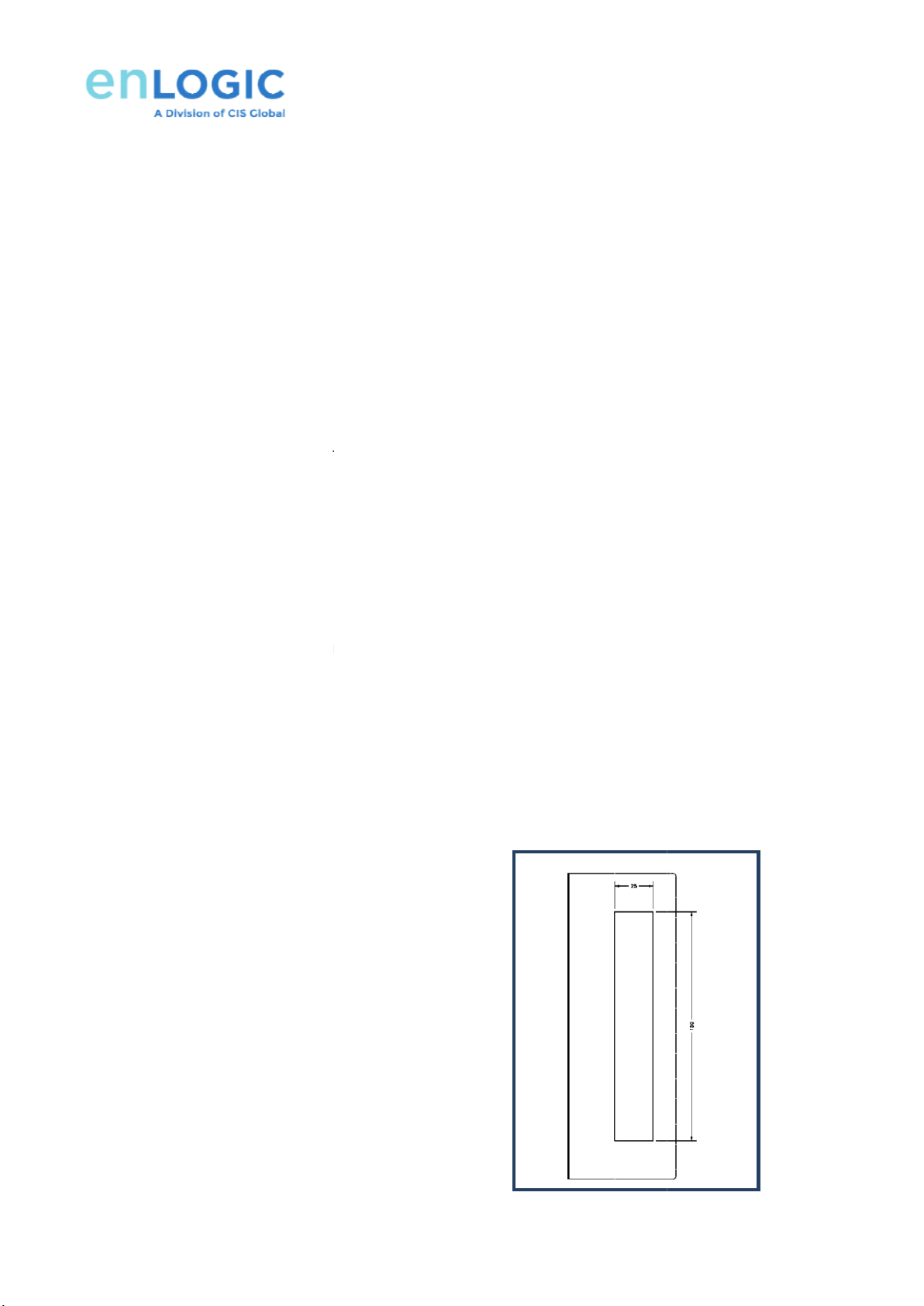
4. Mechanical Requirements
4.1 Cutout dimensions
Cutout width: 25mm +0.3/-
0
Cutout height: 150mm +0.3/
-
General Features
compatible with all applicable SmartZone G5 PDUs
SmartZone G5 1.0 without PowerShare support (with required firmware upgrade).
SmartZone G5 1.5 with PowerShare support.
Future SmartZone G5 PDU versions support.
compatible in fit and function with any SmartZone G5 deployment without disrupting the operation
of the existing G5 PDU and Sensor configuration.
tion of Temperature Sensor Kit (EA001)
No disruption of Temperature & Humidity Sensor Kit (EB001)
No disruption of the (3) Temperature & Humidity Sensor Kit (EC001)
No disruption of Rope Fluid Leak Sensor Kit (ED001)
No disruption of Spot Fluid Leak Sensor
Kit (EE001)
No disruption of Sensor Hub Kit (EF001)
No disruption of Rope Fluid Leak Sensor Extension Kit (EG001)
No disruption of Door Switch Sensor (ACA01)
No disruption of Dry Contact Cable (ACC01)
No disruption of USB Light Strip (ACD01)
of Access Hub (ACB01 & RACB11
-Q )
s Supported per G5 PDU
supported per PDU when not in a daisy chain configuration
supported per PDU when in a daisy chain configuration
supported on Horizontal/Vertical, PowerShare/Non
-PowerShare PDUs
0
-
0
7
compatible in fit and function with any SmartZone G5 deployment without disrupting the operation

Electronic Rack eHandle User Manual
8
4.2 Panel thickness range: 1mm to 2.5mm thick
4.3 Flat CAM Grip range: 15.5mm
4.4 The physical location of the center of the Driver Shaft must be central to the cutout, 25mm below the top of
the panel cutout.
4.5 Recommended mechanical interface between the Driver Shaft and the door locking mechanism
Driver Shaft Critical Dimensions
Cross sectional width: 7.9mm +0/-0.1
Cross sectional height: 7.9mm +0/-0.1
Shaft Protrusion Depth: 3.75mm
Central Thread: M6 threaded hole >= 10mm deep
4.6 Grip Range with 2mm offset CAM: 17.5mm
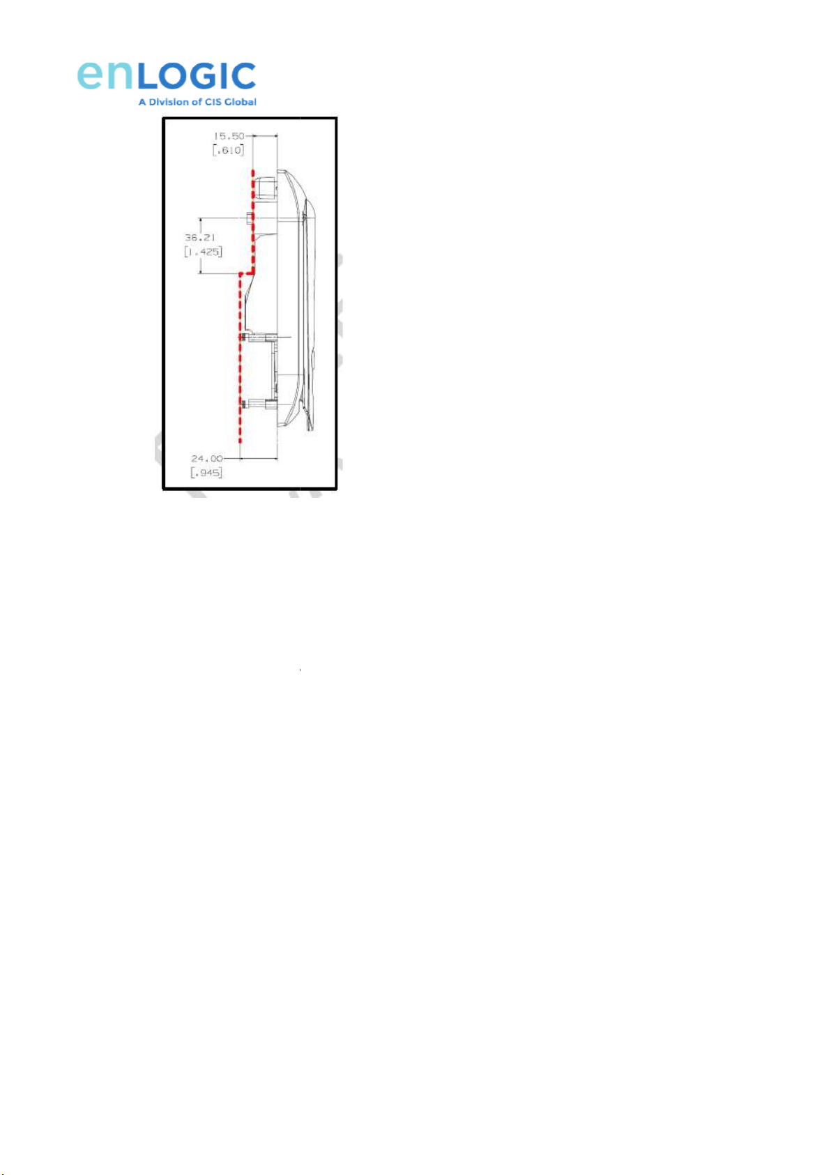
4.7 Clearances behind the eHandle must not be any more restrictive than behind the existing Panduit ACE01,
ACE02 & ACE03 Swinghandles, as detailed below.
15.5mm restriction to extend from the top of the eHandle down to 36.21mm below the center line of the
driver shaft.
24mm restriction to extend onwards from the point 36.21mm below the center of the driver shaft.
4.8 eHandle Support Right-
Hand or Left
4.9 The
Harness shall be routed to the side of
2.3.2 eHandle Lock Function
The eHandle keypad includes
the following features:
Input keys to support (10) inputs:
be numbered from 0 to 9 inclusive
be individual input keys
be all metal construction
be tactile when pressing keys
Key identification numbers and font to be printed in accordance with the published Panduit Branding Guidelines.
Identification numbering must not come off through expected 7 year usage.
No printing to be present on the surface of the keypad
Hand or Left
-Hand installation.
Harness shall be routed to the side of
the eHandle opposite the latch area.
the following features:
Key identification numbers and font to be printed in accordance with the published Panduit Branding Guidelines.
Identification numbering must not come off through expected 7 year usage.
No printing to be present on the surface of the keypad
buttons.
9
Key identification numbers and font to be printed in accordance with the published Panduit Branding Guidelines.

Electronic Rack eHandle User Manual
10
2.3.3 Integrated LED Indicators
Integrated LED indicators are available on all configurations.
Different colors of warning and status of function can be selected by users.
Status LED has the following default configuration which can be controlled by eHandle.
Event LED Status Color Time
Remote unlock Blinking Green Autolock Time
if electronic latch is not closed
after autolock time Blinking Red Autolock Time
Card Swipe Auth success Blinking Green Autolock Time
Card Swipe Auth fail Blinking Red 3 times
eHandle/Mechanical lock is
open by Key Blinking Magenta Door open time
Mechanical Lock Open more
than
door open time Solid Yellow Door open time
Door sensor - Door open more
than
door open time Solid Red Door open time
Door is open for more than MAX
door open time solid red
critical alarm is raised,
no time limit, keep red till
door is not closed
Standby Solid
customer
selectable color
no time limit, changed on
any event, return to original
state after event cleared

Beacon LED has the following default configuration.
Function LED Status
Color
Locate Blinking
Blue, Green,
White, Magenta
Critical
Alarm
Blinking Red
Warning
Alarm
Blinking Yellow
Normal
Status
Solid
Blue, Green,
Yellow, Red,
White, Magenta
Beacon LED has the following default configuration.
Color
Default
Description
Blue, Green,
White, Magenta
Green Identify rack
location. High Intensity.
Customized color.
Red
Any critical alarm in the system
Yellow
Any warning alarm in the system
Blue, Green,
Yellow, Red,
White, Magenta
Led Off
Visual indicator on the PDU, Customized color.
11
Description
location. High Intensity.
Any critical alarm in the system
Any warning alarm in the system
Visual indicator on the PDU, Customized color.
Electronic Rack eHandle User Manual
12
3: eHandle Installation Instruction
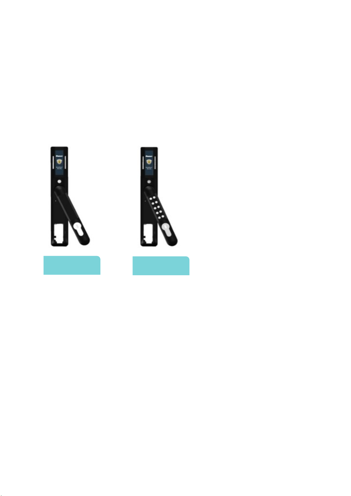
3.1 Types of SmartZone G5 eHandle
EH01: - eHandle RFID (125kHz / 13.56MHz) with integral humidity sensor
EH02: - eHandle RFID (125kHz / 13.56MHz) and Keypad with integral humidity sensor
EH03: - eHandle No Card Reader with integral humidity sensor
EH04: - eHandle No Card Reader and Keypad with integral humidity sensor
ACF01, ACF03 ACF02, ACF04

3.2 eHandle
Included Installation Parts
Included Installation Parts
13
Electronic Rack eHandle User Manual
14
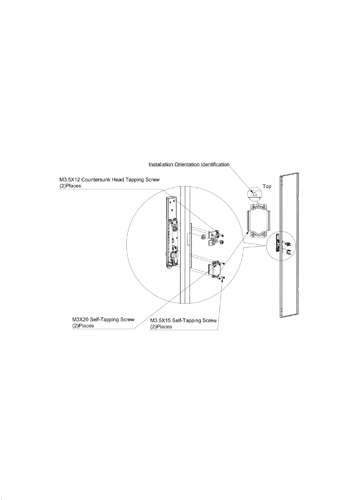
3.3 eHandle Lock Mounting Option for Front and Rear Door
3.3.1 If needed, remove any existing lock mechanism. Save the Cam (latch) for later steps.
NOTE: The eHandle’s lock requires a cut-out of 150x25mm. Reference Figure below for the following steps.
3.3.2 Position the lock body within the cut-out and flush to the outer face of the cabinet door. Use the 12mm Top
Mounting Screws and Top Mounting Bracket to secure the lock to the door.
3.3.3 Select a suitable Rotation Limiter (standard or extended) and mount the cam assembly from Step 1. Secure
using the included Cam Screw. Pay careful attention to the orientation of the Rotation Limiter according to
your installation requirements.
3.3.4 Ensure that the orientation of the lock plug corresponds to the orientation of the Bottom Mounting Bracket
and install the Bracket using the included 15mm and 20mm Bottom Mounting Screws.
4: eHandle
WEB Configuration
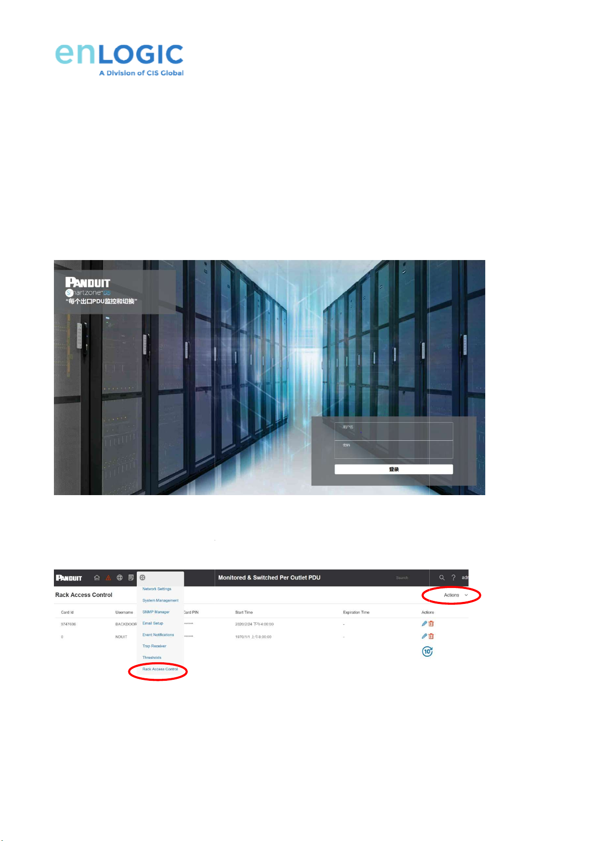
4.1 ID User Authorization
Once connected, users can be assigned HID cards to complete authentication & authorization
Please go to
PDU web by ip address (can get from PDU screen)
Username: admin
Password: 12345678
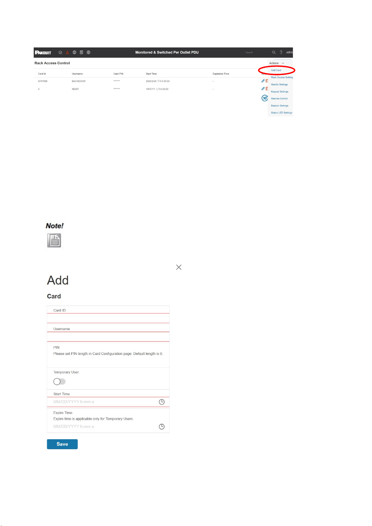
ID User Authorization/Add Card
1. The
Administrator can use Web Interface or SNMP to create user entry with an associated ID card. Go to Smart
Rack Access Control>Actions>Add Card.
WEB Configuration
4.1 ID User Authorization
/Add Card
Once connected, users can be assigned HID cards to complete authentication & authorization
PDU web by ip address (can get from PDU screen)
, and enter a username and
password to
Administrator can use Web Interface or SNMP to create user entry with an associated ID card. Go to Smart
Rack Access Control>Actions>Add Card.
15
Once connected, users can be assigned HID cards to complete authentication & authorization
.
password to
log in.
Administrator can use Web Interface or SNMP to create user entry with an associated ID card. Go to Smart
Electronic Rack eHandle User Manual
16
2. Input the Card ID, user name, PIN and date, then click save to add a Card.
3. Each code can be assigned a User Name up to 31 characters long. Note: User name is related to filed name.
4. Expiration time is only applicable to temporary users. After the expiry Date/Time, the expired ID code will no longer
be valid. (start when it’s created).
5. Click Save to complete Add Card.
If authentication failed, the LED will blink Red three times. The default color is Red.
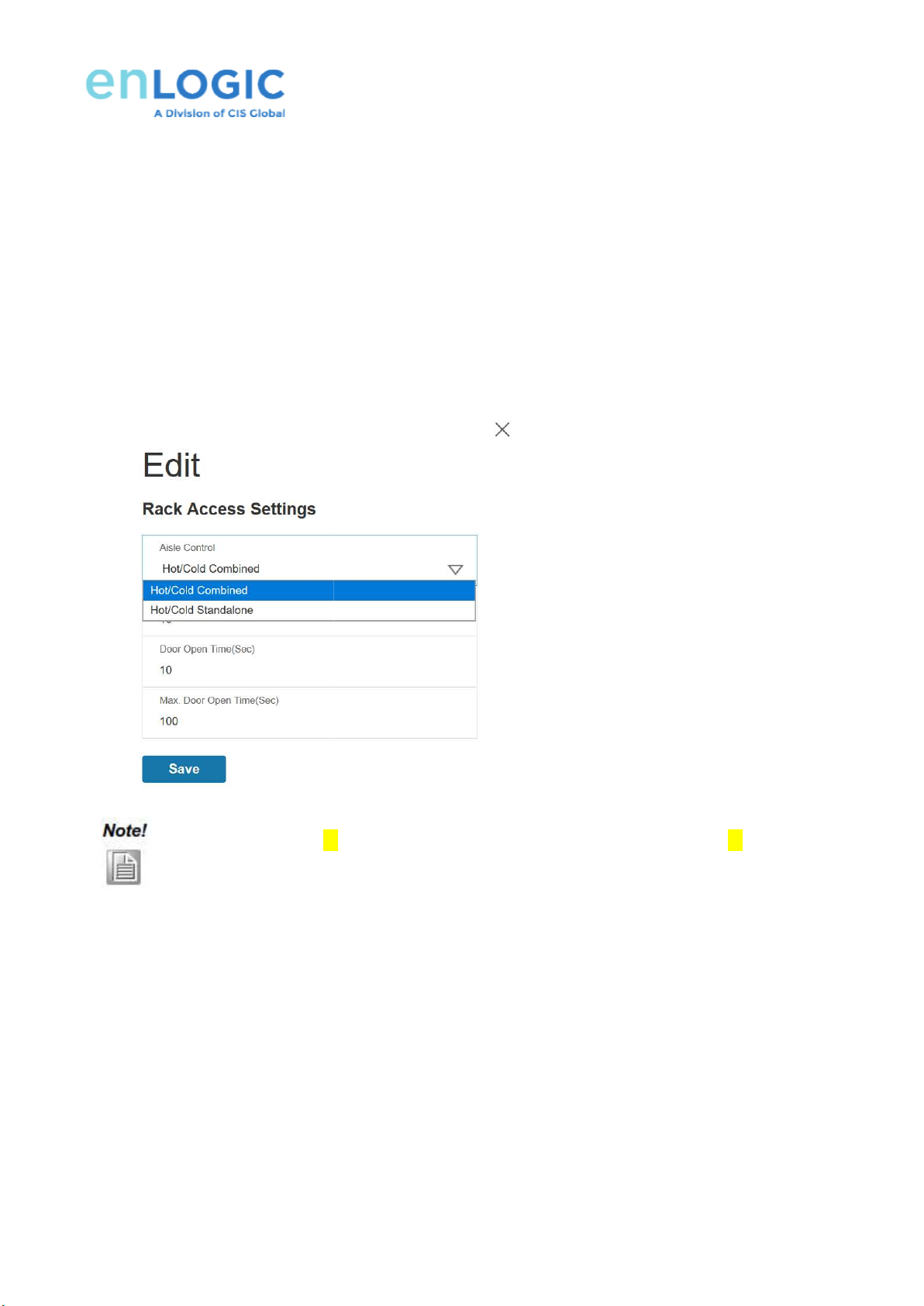
4.2 Rack Access Settings
For Rack Access Settings, please g
o to Smart Rack
Select Aisle Control. Two options can be selected which are Hot/Cold Combined and
Hot/Cold Standalone– W
hen this is selected
aisle can control cold aisle.
Hot/Cold Combined – W
hen this is selected
control cold aisle.
Select Autolock
Time and Door Open Time as 10 seconds. Max Door Open Time is set as 100 seconds.
Click Save to complete Rack Access Settings.
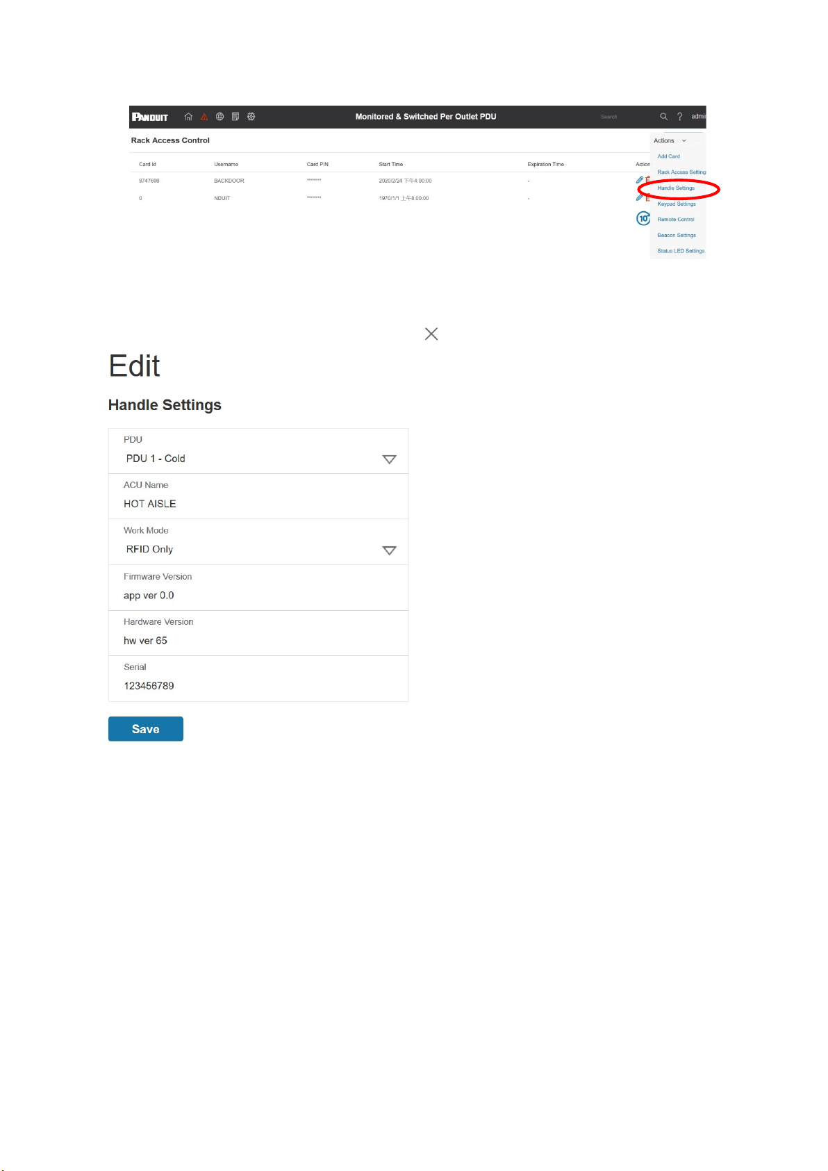
4.3 eHandle Settings
For eHandle Settings, please g
o to Smart Rack
Select PDU
Input ACU name such as
HOT AISLE.
Select eHandle Work Mode.
Currently
Firmware version, hardware version and serial number are Read Only.
Click Save to complete
eHandle
Lock not sensed after
xx
and door sensor is not sensed
o to Smart Rack
Access Control>Actions>
Rack Access Settings
Select Aisle Control. Two options can be selected which are Hot/Cold Combined and
hen this is selected
, aisle control is individual. Hot aisle
hen this is selected
, one
aisle can be controlled by opposite aisle.
Time and Door Open Time as 10 seconds. Max Door Open Time is set as 100 seconds.
Click Save to complete Rack Access Settings.
o to Smart Rack
Access Control>Actions>eHandle Settings
.
HOT AISLE.
Currently
RFID only mode can be selected.
Firmware version, hardware version and serial number are Read Only.
eHandle
Settings.
xx
seconds and door sensor is sensed, or Lock not sensed after
and door sensor is not sensed
. LED blinks YELLOW for Door Open Time(Sec)
.
17
Rack Access Settings
.
Select Aisle Control. Two options can be selected which are Hot/Cold Combined and
Hot/Cold Standalone.
can control hot aisle, cold
aisle can be controlled by opposite aisle.
Hot aisle can
Time and Door Open Time as 10 seconds. Max Door Open Time is set as 100 seconds.
.
seconds and door sensor is sensed, or Lock not sensed after
yy seconds
.
Electronic Rack eHandle User Manual
18
4.4 Keypad Settings
For Keypad Settings, please go to Smart Rack Access Control>Actions>Keypad Settings.
Keypad Settings can be achieved through WEB interface or SNMP.
1) PIN Code length 1 to 15 numeric digits 0 to 9 (default is blank), can be updated in WEB and SNMP, no entry in the
MIB.
2) Each PIN code can be assigned a Name up to 31 characters long.
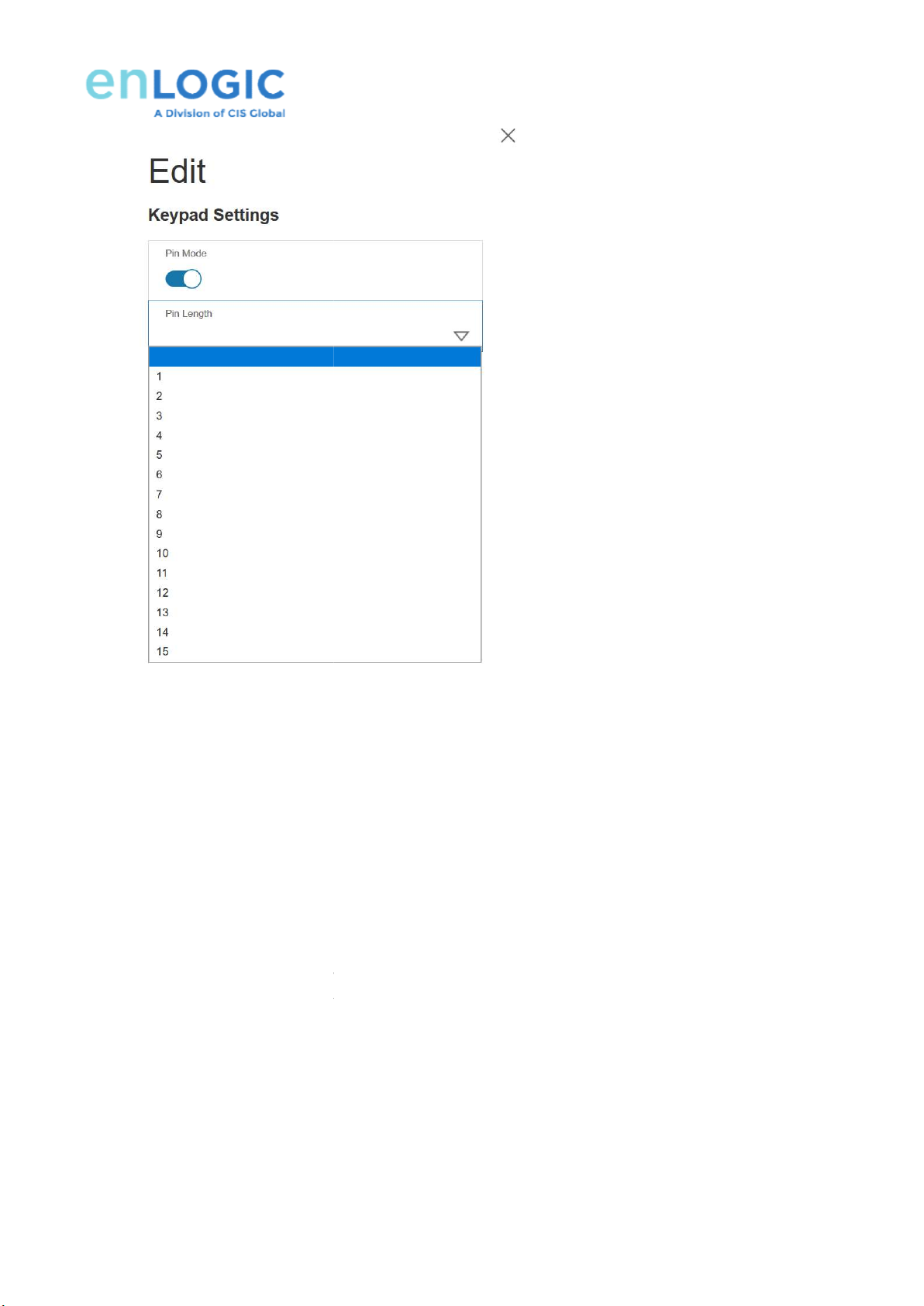
3) Each co
de can be entered in a hidden way such a *(invisible by the user) or readable
This is configurable by pin mode in WEB GUI (Graphical User Interface). When pin mode is active, pin is hidden and
displayed as *. When pin mode is disables, pin is
4)
Hidden codes are reset to blank if the user changes from Hidden mode to Readable mode.
5)
6 PIN entry uses a 5 second key to key press timeout.
6)
Click Save to complete Keypad Settings.
4.5 Remote Control
4.5.1 Please go to Smart Rack
Access Control
The HID card can now be used to access
Web. Hot Aisle
can be selected in Aisle options.
de can be entered in a hidden way such a *(invisible by the user) or readable
(plain text).
This is configurable by pin mode in WEB GUI (Graphical User Interface). When pin mode is active, pin is hidden and
displayed as *. When pin mode is disables, pin is
visible.
Hidden codes are reset to blank if the user changes from Hidden mode to Readable mode.
6 PIN entry uses a 5 second key to key press timeout.
Click Save to complete Keypad Settings.
Access Control
>Actions>Remote Control.
The HID card can now be used to access
to the rack. In addition, a eHandle can be
also
can be selected in Aisle options.
19
(plain text).
This is configurable by pin mode in WEB GUI (Graphical User Interface). When pin mode is active, pin is hidden and
Hidden codes are reset to blank if the user changes from Hidden mode to Readable mode.
also
set by remote control in

Electronic Rack eHandle User Manual
20
Clicking Lock/Unlock/ on the interface can realize the remote control of the eHandle on site.
But actually clicking Unlock on the interface, the Status on the panel is LOCK.
Clicking Lock on the interface, the Status on the panel is CLOSED.
Picture
This manual suits for next models
22
Table of contents


