Telco Sensors SpaceMaster Series User manual

SMRR 7000-IO - USER MANUAL EN
SpaceMaster Series
Photoelectric retro-reflective sensors with IO-link
Website: www.telcosensors.com
Warning
V 1.0 Part Number: L40-0666220939
E-Mail: info@telcosensors.com
This device is not to be used for Personnel Protection in Machine
Guarding Safety applications. This device does not include the self-
checking redundant circuitry necessary to allow its use in personnel
machine guarding stand-alone safety applications.
October 2021 edition
Made in Denmark
Telco A/S reserves the right to make changes without prior notice
tel
Product Data
Electrical Data
Supply Voltage
10 – 30 V dc
Voltage ripple
+/- 15%
Current consumption
30 mA
Max. output load
200 mA / 30 V dc
Reverse polarity protected
Yes
Short circuit protected
Yes
Environmental Data
Temperature, operation
-20 to +60 ºC
Sealing class
IP 67
Approvals
Available Models
Model
Supply
Voltage
Output
Output
Mode
Sensing
Range
Diffuse
Proximity
SMRR 7400 IO xx x 10-30 V
dc
IO-Link/NPN
Light/dark 0 – 3m*
SMRR 7500 IO xx x IO-Link/PNP
* Note: Measured against the Ø85 mm retro-reflector.
Illustration
Connection
Wiring Diagrams
SMRR 7400 IO
Load as NPN
SMRR 7500 IO
Load as PNP
Connection Pins
4 pin, M8 plug
4 pin, M12 plug
Supply +
Brown
Pin 1
Pin 1
Supply -
Blue
Pin 3
Pin 3
IO-Link
Black
Pin 4
Pin 4
Control/Output
White
Pin 2
Pin 2
Sensor plug
Sensor plug
Mounting & Installation
Mounting & Installation
1 Position the sensor pointing at the target object.
2 Align by moving sensor horizontally and vertically until the output changes when the
target object is present (refer to Output Logic table).
3 Fasten the sensor securely using the enclosed locking nuts and/or a mounting bracket.
Avoid acute angles on cable close to sensor.
Adjustments
General
Sensitivity and output mode can be adjusted using the potentiometers or with the IO-Link.
The IO-Link allows the user to setup and read several functions and parameters. Please refer to
“SMRR and PC connection” on the following page.
Output Mode Selection
The output mode can be selected via an integral light/dark switch, or via IO-Link. Refer to Output
Logic table for output mode reference. Note that the NPN output is closed when IO-Link/push-
pull is low and the yellow output LED is off.
Light Operated (N.C.) Enables the output to be inactive
when there is an object present.
Turn switch to full clockwise
position, or set:
- Overwrite light operated = true
- Light operated = true
in the Parameters tab.
Dark Operated (N.O.) Enables the output to be active
when there is an object present.
Turn switch to full counter
clockwise position, or set:
- Overwrite light operated = true
- Light operated = false
in the Parameters tab.
Output Logic
Detection Output mode
Output status
Yellow LED
IO-Link
PNP
NPN
Object present
Light operated
(N.C.) Low Open Closed Off
Dark operated
(N.O.) High Closed Open On
Object absent
Light operated
(N.C.) High Closed Open On
Dark operated
(N.O.) Low Open Closed Off
Sensitivity Adjustment
Maximum sensitivity can be used for most applications and is advised for applications with
contaminated environments. The sensitivity can be adjusted on the potentiometer (factory
default active) or via IO-Link.
Sensitivity adjustment may be required in applications where objects to be detected have
highly reflective, dark or textured surfaces and/or applications where a background is present.
This can be achieved manually or via IO-Link.
For sensitivity adjustment, proceed with the following steps:
1 Start with the sensitivity at minimum by turning the potentiometer to full counter
clockwise position, or by setting the Gain value to 255.
2 Select target object with the smallest dimensions and most translucent surface.
3
Place target object between the sensor and retro-reflector. If the output status
changes, adjustment is not required. If the output has not changed proceed to step
4.
4
Decrease the sensitivity by turning the potentiometer counter clockwise or decrease
the Gain value to a lower value until the output changes.
If the output has not changed, attempt to move the sensor and retro-reflector further
apart or angle the sensor/retro-reflector. Then repeat procedure from step 1.
Alternatively, remove any object and press teach-gain button using IO-link.
5 Remove target object. Check the output status has changed.
!
SMRR 7000-IO - USER MANUAL EN
SpaceMaster Series
Photoelectric retro-reflective sensors with IO-link
Website: www.telcosensors.com
Warning
V 1.0 Part Number: L40-0666220939
E-Mail: info@telcosensors.com
This device is not to be used for Personnel Protection in Machine
Guarding Safety applications. This device does not include the self-
checking redundant circuitry necessary to allow its use in personnel
machine guarding stand-alone safety applications.
October 2021 edition
Made in Denmark
Telco A/S reserves the right to make changes without prior notice
tel
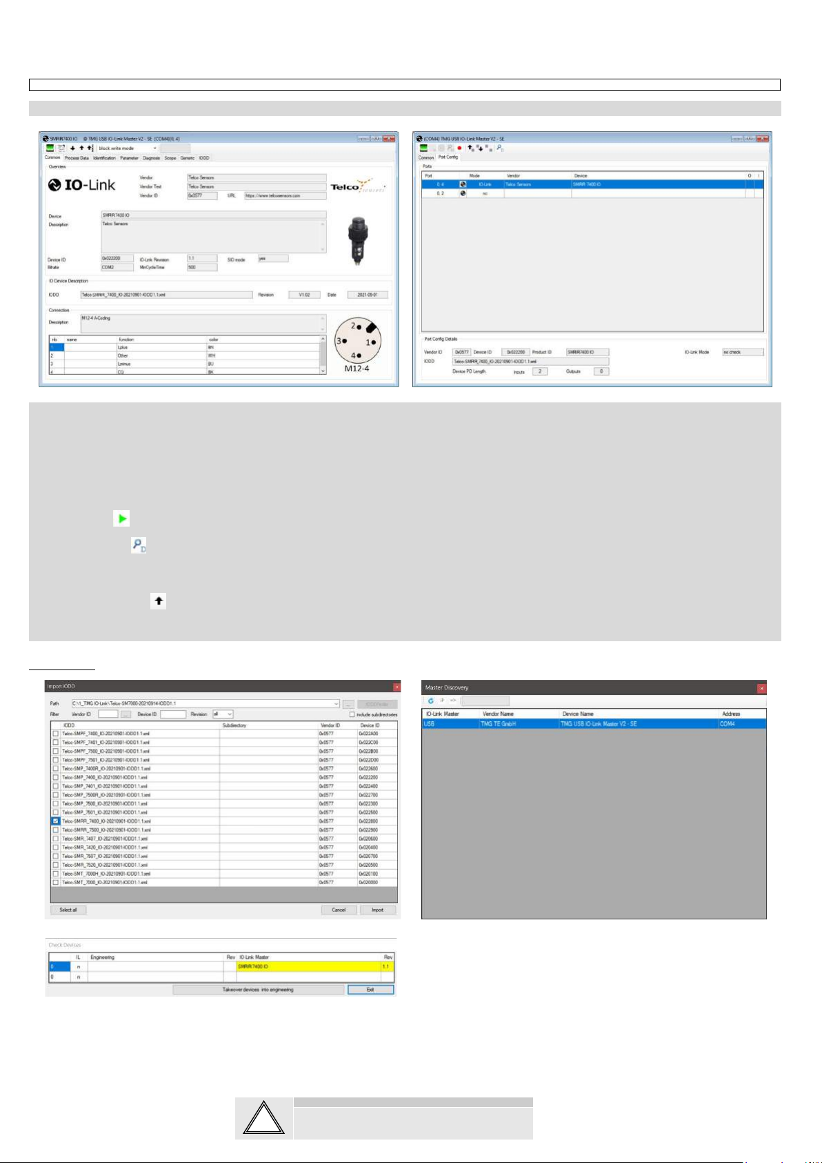
SMRR and PC connection
To setup or adjust a SMRR, it is required to use TMG IO-Link Device Tool together with TMG-USB IO-Link Master, or another IO-Link PC application.
How to connect
Connect the TMG-USB IO-Link Master USB-adapter to the USB-port of the PC and to the cable of the SMRR.
Download the IO-Link Device Tool software and the SMRR-IODD file from the Telco Sensors website in https://www.telcosensors.com/downloads selecting Software in Document type section.
Install the TMG IO-Link Device Tool V5.1.1-5122 SE – Setup file and run the program.
Import the SMRR-IODD by selecting “Import IODD” in the Options menu, previously downloaded.
Click on “Search Master” and select the Master in the popup window.
Click on “Go Online” .
Click on “Check Devices” .
Click on “Takeover devices into engineering” to the SMRR device.
Double click on the row with the SMRR, to open the Device menu.
Click on “Upload from Device”to upload the SMRR settings.
For more information see TMG’s User Manual for the IO-Link Device Tool.
Popup windows:
!
SMRR 7000 IO USER MANUAL EN
SpaceMaster Series
Photoelectric retro-reflective sensors with IO-link
Website: www.telcosensors.com
Warning
V 1.0 Part Number: L40-0666220939
E-Mail: info@telcosensors.com
This device is not to be used for Personnel Protection in Machine
Guarding Safety applications. This device does not include the self-
checking redundant circuitry necessary to allow its use in personnel
machine guarding stand-alone safety applications.
October 2021 edition
Made in Denmark
Telco A/S reserves the right to make changes without prior notice
tel
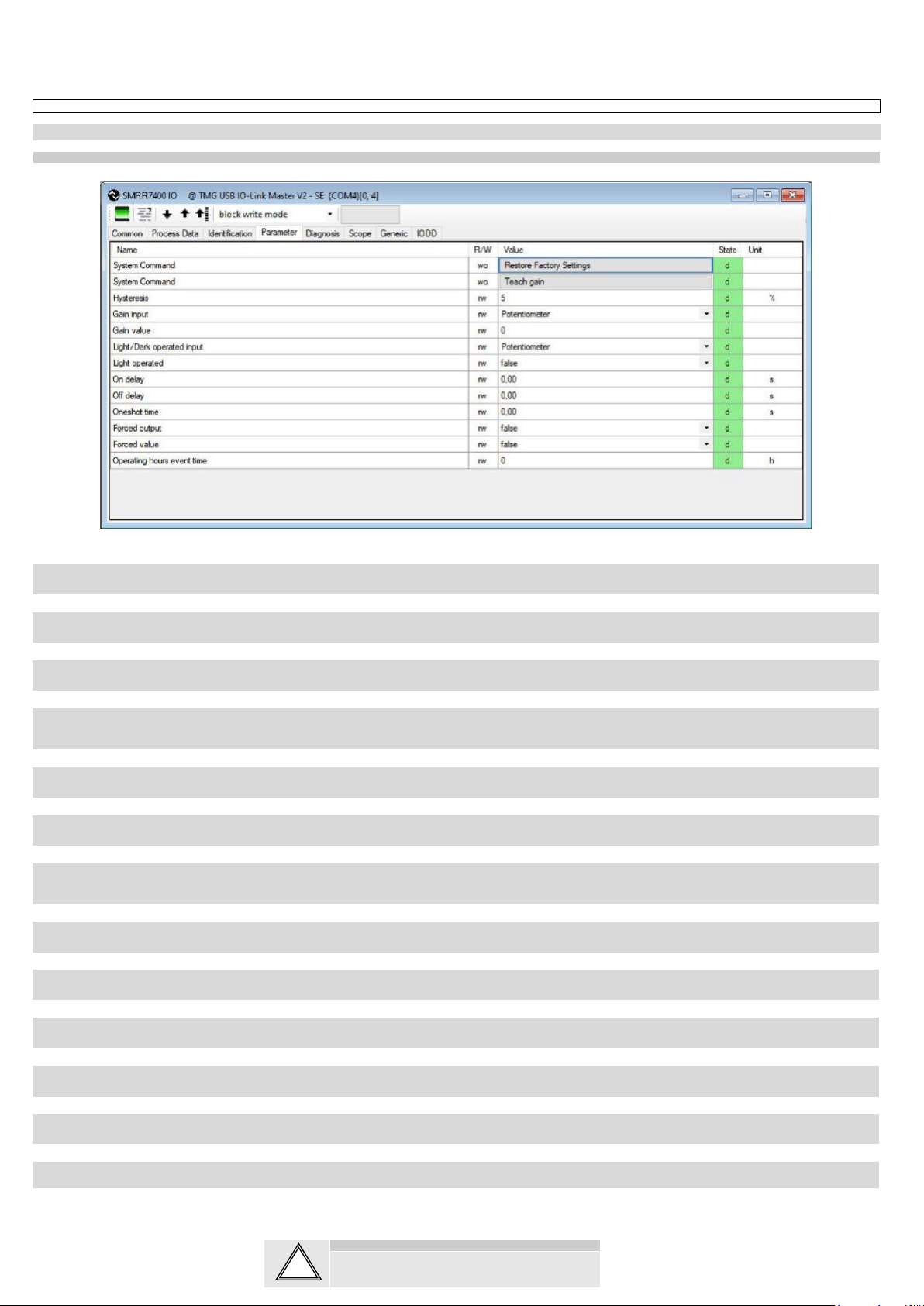
Parameters
On the Parameter tab, the parameters of the sensor can be set up or modified.
General settings SMRR:
System Command - Restore Factory Settings
Restores all user-settings to default values.
System Command – Teach Gain
Determines the lowest possible gain to turn on.
Hysteresis
The relative difference between on and off threshold. In both IO-Link and Potentiometer gain input it is possible to set the Hysteresis level. It can be set from 0 to 10%.
Gain input
Select how the gain should be controlled. Select between Potentiometer or IO-Link. IO-Link is set by the Gain value setting. Keep objects out of the detection area when switching to teach-in mode,
because the initial setting of the beam requires information about signal strength for an unbroken beam. Excess gain is adjusted to about 2.
Gain value
Select a fixed gain when IO-Link is selected for Gain input. It can be set from 0 to 255.
Light/Dark operated input.
How the light/dark operated should be determined. Select between Potentiometer or IO-Link.IO-Link is set by the “Light operated” value setting. Potentiometer is set by the potentiometer on the sensor.
Light operated
Select between true or false.
Changing the selection will invert the outputs, if the Overwrite light operated is true.
On delay
Select the delay of the output when an object appears, i.e. becomes present. It can be set from 0,00 to 600,00 seconds.
Off delay
Select delay of the output when an object disappears, i.e. becomes absent. It can be set from 0,00 to 600,00 seconds.
Oneshot time
Select how long time the outputs will be active when going from not active to active. It can be set from 0,00 to 600,00 seconds.
Forced output.
Select if the output should be forced to the value in Forced value or decided from the sensor input.
Forced value
Select the output state if the Forced output is true.
Operating Hours Event Time
Starts an event message when operating hours reaches the value. It can be set from 0 to 4294967295. If 0 is selected there will be no operating hours event.
!
SMRR 7000 IO USER MANUAL EN
SpaceMaster Series
Photoelectric retro-reflective sensors with IO-link
Website: www.telcosensors.com
Warning
V 1.0 Part Number: L40-0666220939
E-Mail: info@telcosensors.com
This device is not to be used for Personnel Protection in Machine
Guarding Safety applications. This device does not include the self-
checking redundant circuitry necessary to allow its use in personnel
machine guarding stand-alone safety applications.
October 2021 edition
Made in Denmark
Telco A/S reserves the right to make changes without prior notice
tel
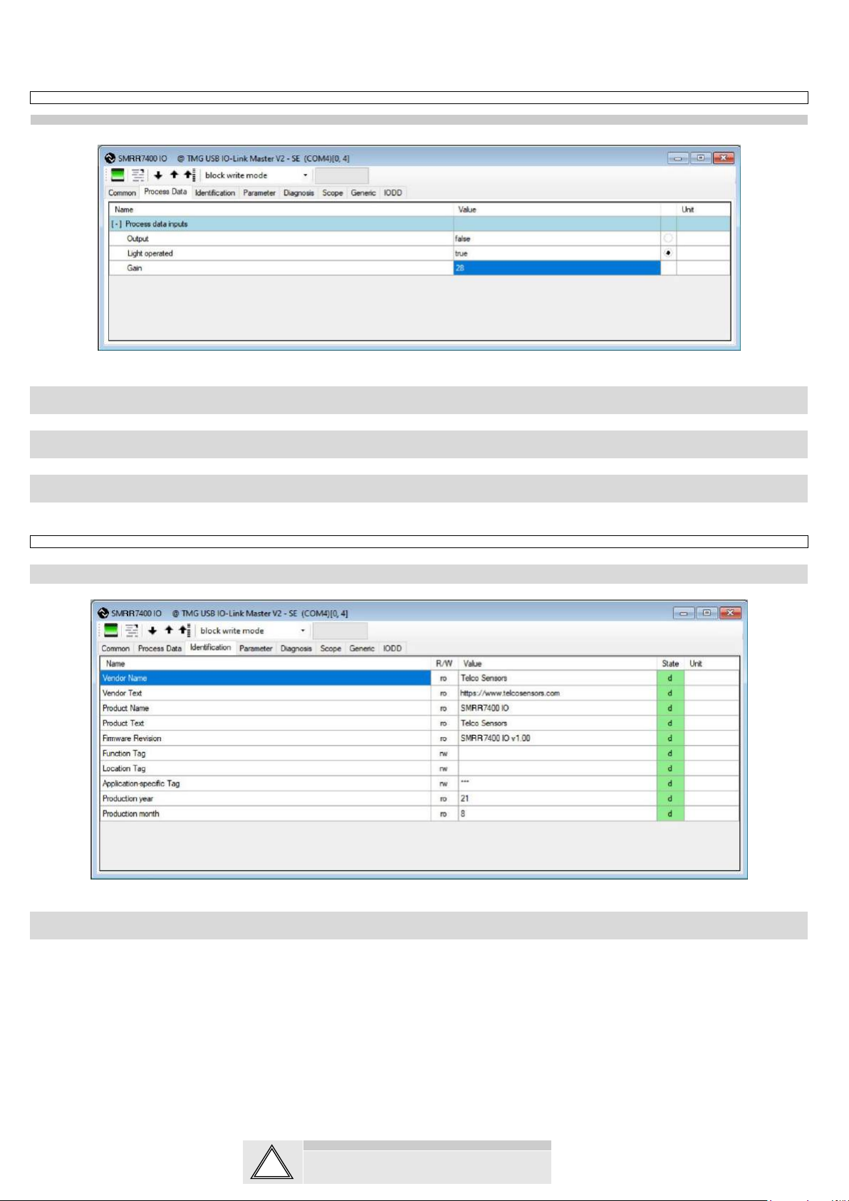
Process Data
Process data SMRR:
Output
Status on the output.
Light Operated
Status on the light operated selection.
Gain
Status on the gain value.
Identification
On the identification tab, general information about the sensor is displayed.
Function Tag, Location Tag and Application-specific Tag
Enter user specific descriptions for identification.
!
This manual suits for next models
1
Other Telco Sensors Accessories manuals

Telco Sensors
Telco Sensors SpaceMaster Series User manual

Telco Sensors
Telco Sensors SpaceMaster Series User manual

Telco Sensors
Telco Sensors Space Scan Series User manual

Telco Sensors
Telco Sensors Space Guard Series User manual

Telco Sensors
Telco Sensors SM 3000/CAT2 Series User manual

Telco Sensors
Telco Sensors SpaceMaster Series User manual


