Cisal Less Minimal LM00051 User manual


2
ATTENZIONE: Consegnare per cortesia queste istruzioni all’utilizzatore della rubinetteria.
ATTENTION: Livrer, s’il Vous plait, ces instructions aux acheteurs de la robinetterie.
WARNING: Please give these instructions to the taps’ buyers.
ATENCION: Favor entregar estas instrucciones a los adquirentes de los grifos.
ACHTUNG: Geben Sie bitte den Käufern der Armatur diese Anweisung.
OPGELET: Bij de levering van kraanwerk, gelieve de gebruiksvoorwaarden en Onderhouds-methoden mee te leveren.
Fig. 1
Abb. 1
Afb. 1
LM00051
LM00152 LM00055
LM00151 LM00052
3
Fig. 3
Abb. 3
Afb. 3
Fig. 2
Abb. 2
Afb. 2
CHIAVE DINAMOMETRICA
CLÈ DYNAMOMÈTRIQUE
DYNAMOMETRIC WRENCH
LLAVE DINAMOMÈTRICA
DREHMOMENTENSCHLÜSSEL
SLEUTEL MET REGELBARE KOPPEL
7 N•m

4
INFORMAZIONI PRELIMINARI
I miscelatori della serie LESS MINIMAL sono idonei al
funzionamento con accumulatori di acqua calda in
pressione, scaldaacqua istantanei elettrici ed a gas.
ATTENZIONE: non è possibile l’allacciamento ad accumulatori
di acqua calda senza pressione (a circuito aperto).
DATI TECNICI
- Pressione dinamica minima . . . . . . . . . . . . . . . . 0,5 bar
- Pressione massima di esercizio (statica) . . . . . . . 10 bar
- Pressione di esercizio raccomandata (statica) . . . 1-5 bar
(N.B.: per pressioni superiori a 5 bar si consiglia di
installare un riduttore di pressione)
- Pressione massima di prova (statica) . . . . . . . . . 16 bar
- Temperatura acqua calda massima . . . . . . . . . . 80 °C
- Temperatura acqua calda consigliata . . . . . . . . . 60°C
(per risparmio energetico)
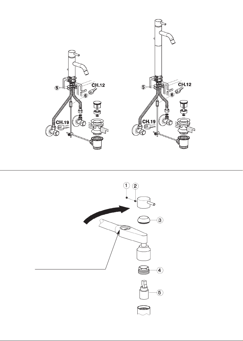
INSTALLAZIONE (rif. FIG.1 - FIG.2)
- Avvitare i flessibili [1] al miscelatore utilizzando una chiave
da 11 mm posizionandola nelle apposite fresature.
- IMPORTANTE: durante le operazioni di montaggio dei
flessibili NON FARE ASSOLUTAMENTE presa sulle bussole
dei flessibili stessi con chiavi esagonali o pinze regolabili
che, danneggiandole, comprometterebbero la sicurezza
dell’installazione (vedi FIG.1).
- Avvitare il gambo di fissaggio [2] al miscelatore.
- Inserire l’astina di comando [3] e avvitarla al pomello [4].
- Fissare il miscelatore alla ceramica tramite staffa di
fissaggio [5] e controdado esagono 12 mm [6] (vedi FIG.2).
- Collegare il miscelatore all’ impianto serrando le calotte da
G.3/8” dei flessibili con una chiave da 19 mm.
- Montare lo scarico automatico e collegarlo all’astina di
comando tramite morsetto (fornito in dotazione).
- Aprire le mandate delle acque e verificare la tenuta dei
raccordi e il funzionamento del miscelatore (pressione
massima di prova 16 bar statica).
SOSTITUZIONE DELLA VALVOLA MISCELATRICE
A DISCHI CERAMICI (rif. FIG.3)
- Chiudere le entrate dell’ acqua calda e dell’ acqua fredda.
- Togliere la placchetta di copertura foro [1] e svitare il grano
di bloccaggio [2] utilizzando una chiave a brugola da 2,5
mm.
- Sfilare la leva e scalzare il cappuccio [3] tirandolo verso
l’alto.
- Svitare la calotta [4] tramite chiave da 25 mm e sfilare la
valvola miscelatrice [5].
- Inserire la nuova valvola miscelatrice facendo attenzione
che non rimanga sporcizia tra piano e guarnizioni.
- Avvitare la calotta [4] tramite CHIAVE DINAMOMETRICA
applicando una coppia di serraggio 7 N•m.
- Inserire il cappuccio e rimontare la leva.
INFORMATIONS PRÉLIMINAIRES
Les mélangeurs de la série LESS MINIMAL sont aptes au
fonctionnement avec accumulateurs d’eau chaude en
pression, chauffe-bains instantanés et à gaz.
ATTENTION: la connexion avec accumulateurs d’eau
chaude sans pression (à circuit ouvert) n’est pas possible.
DONNÉES TECHNIQUES
- Pression dynamique minimum . . . . . . . . . . . . . 0,5 bar
- Pression maximum de service (statique) . . . . . . . 10 bar
- Pression de service recommandée (statique) . . . 1-5 bar
(N.B.: pour pressions supérieures à 5 bar on conseille
d’installer un réducteur de pression)
- Pression maximum d’épreuve (statique) . . . . . . . 16 bar
- Température eau chaude maximum . . . . . . . . . . 80 °C
- Température eau chaude conseillée . . . . . . . . . 60 °C
(pour économies d’énergie)
INSTALLATION (réf. Fig. 1 - Fig. 2 )
- Visser les flexibles (1) au mélangeur en utilisant une clé de
11 mm en la positionnant dans les fraisures spéciales.
- IMPORTANT: pendant les opérations de montage des
flexibles NE PAS FAIRE prise sur les douilles des flexibles
mêmes avec clés hexagonales ou pinces réglables qui, en
les endommageant, porteraient préjudice à la sécurité de
l’installation (voir Fig. 1).
- Visser le support de fixage (2) au melangeur.
- Introduire la tige de commande (3) et la visser au
pommeau (4).
- Fixer le mélangeur à la céramique par étrier de fixation (5)
et contre-écrou hexagone 12 mm (6) (voir Fig. 2).
- Connecter le mélangeur à l’installation en serrant les
écrous de G3/8’’ des flexibles avec une clé de 19 mm.
- Monter le vidage automatique et le connecter à la tige par
jonction (fourni).
- Ouvrir les conduits des eaux et vérifier l’étanchéité des
raccords et le fonctionnement du mélangeur (pression
maximum d’épreuve 16 bar statique).
REMPLACEMENT DE LA CARTOUCHE
À DISQUES CÉRAMIQUES (réf. Fig. 4)
- Fermer les entrées de l’eau chaude et de l’eau froide.
Enlever la plaquette de couverture trou (1) et dévisser le
grain de blocage (2) en utilisant une clé hexagonale de
2,5 mm
- Extraire le levier et ôter la rosace (3) en tirant vers le haut.
- Dévisser l’écrou (4) avec la clé de 25 mm et extraire la
cartouche (5).
- Insérer la nouvelle cartouche en faisant attention qu’il ne
reste pas des incrustations entre plan et joints.
- Visser l’écrou (4) avec CLÉ DYNAMOMÉTRIQUE en
appliquant un couple de serrage de 7 N•m.
- Insérer la rosace et remonter le levier.
I F

5
PRELIMINARY INFORMATION
Mixers of the LESS MINIMAL series are fit for operating with
hot water collectors under pressure, instantaneous and gas
water-heaters.
ATTENTION: the connection with hot water collectors
without pressure (with open circuit) is not possible.
TECHNICAL DATA
- Minimum dynamic pressure . . . . . . . . . . . . . . . . 0,5 bar
- Maximum operational pressure (static) . . . . . . . . 10 bar
- Recommended operational pressure (static) . . . . 1-5 bar
(N.B.: for pressures higher than 5 bar we suggest the
installation of a pressure reducer)
- Maximum test pressure (static) . . . . . . . . . . . . . . 16 bar
- Maximum hot water temperature . . . . . . . . . . . . 80 °C
- Suggested hot water temperature . . . . . . . . . . . 60 °C
(for energy saving)
INSTALLATION (ref. Fig. 1 - Fig. 2 )
- Screw the flexible hoses (1) to the mixer using a 11 mm
wrench positioning it in the special millings.
- IMPORTANT: during the flexible hoses’ assembly
operations, DO NOT HOLD the sleeves of the flexible hoses
with hexagonal wrenches or adjustable pincers that,
damaging them, would compromise the safety of the
installation (see Fig. 1).
- Insert the rod (2) of the pop-up.
- Assemble the rod (3) and screw it on the knob (4).
- Clamp the mixer to the ceramics with the clamping vice (5)
and hexagonal lock-nut of 12 mm (6) (see Fig. 2).
- Connect the mixer to the plant screwing the G3/8’’ nuts of
the flexible hoses with a 19 mm wrench.
- Assemble the automatic pop-up and connect it to the rod
with the (supplied) connection.
- Open the water pipes and check the tightness of the
connections and the operation of the mixer (maximum test
pressure 16 bar static).
REPLACEMENT OF THE MIXING VALVE WITH
CERAMIC DISCS (ref. Fig. 3)
- Close the hot water and cold water inlets.
- Remove the plate for covering the hole (1) and unscrew the
locking pin (2) using a hexagonal wrench of 2,5 mm
- Remove the lever and the cap (3) pulling upwards.
- Unscrew the caps (4) with the 25 mm wrench and remove
the mixing valve (5).
- Insert the new mixing valve verifying that no dirt is left
between the plane surface and the gaskets.
- Screw the caps (4) by DYNAMOMETRIC WRENCH
applying a screwing torque of 7 N•m.
- Insert the cap and reassemble the lever.
INFORMACIÓN PRELIMINAR
Los mezcladores de la serie LESS MINIMAL son idoneos para
el funcionamiento con acumuladores de agua caliente bajo
presión, calderas instantáneos eléctricos y a gas.
ATENCION: la conexión con acumuladores de agua
caliente sin presión (circuito abierto) no es posible.
DATOS TÉCNICOS
- Presión dinámica mínima . . . . . . . . . . . . . . . . . . 0,5 bar
- Presión máxima de trabajo (estática) . . . . . . . . . 10 bar
- Presión de trabajo recomendada (estática) . . . . . 1-5 bar
(N.B.: para presiones superiores a los 5 bar Les
recomendamos instalar un reductor de presión)
- Presión máxima de prueba (estática) . . . . . . . . . 16 bar
- Temperatura máxima agua caliente . . . . . . . . . . 80 °C
- Temperatura aconsejada agua caliente . . . . . . . 60 °C
(para ahorrar de energía)
INSTALACIÓN (ref. Fig. 1 - Fig. 2 )
- Atornillen los flexibles (1) al mezclador utilizando una llave
de 11 mm, colocándola en los fresados correspondientes.
- IMPORTANTE: durante las operaciones de montaje de los
flexibles NO HAGAN fuerza sobre los bujes de los mismos
flexibles utilizando llaves hexagonales o pinzas ajustables
que, dañándolos, podrían perjudicar la seguridad de la
instalación (vean Fig. 1).
- Atornillen el vástago de fijación (2) al mezclador.
- Introduzcan la varilla de mando (3) y atorníllenla al pomo
(4).
- Fijen el mezclador a la cerámica a través de un estribo de
fijación (5) y un contra-dado hexagonal de 12 mm (6)
(vean Fig. 2).
- Conecten el mezclador a la instalación, cerrando los
casquillos de G3/8’’ de los flexibles con una llave de 19 mm.
- Monten el desagüe automático y conéctenlo a la varilla
utilizando la clavija incluida en el suministro.
- Abran la alimentación del agua y verifiquen el cierre de los
connexiones y el funcionamiento del mezclador (presión
máxima de ensayo: 16 bar, estática).
SUSTITUCIÓN DE LA VÁLVULA MEZCLADORA
CON DISCOS CERÁMICOS (ref. Fig. 4)
- Cierren las entradas del agua caliente y del agua fría.
- Quiten la placa de cobertura del agujero (1) y destornillen
el perno de fijación (2) utilizando una llave hexagonal de
2,5 mm.
- Extraigan la maneta y suelten el capuchón (3) tirando
hacia arriba.
- Destornillen el casquillo (4) con una llave de 25 mm y
extraigan la válvula mezcladora (5).
- Introduzcan la nueva válvula mezcladora cuidando con
que no quede incrustaciones entre el llano y las juntas.
- Atornillen el casquillo (4) con la LLAVE DINAMOMÉTRICA,
aplicando un par de apriete de 7 N•m.
- Introduzcan el capuchón y vuelvan a montar la maneta.
EGB

6
ALLGEMEINE INFORMATION
Die Mischbatterien der Serie LESS MINIMAL sind für die
Funktionstätigkeit mit Warmwasserspeichern unter Druck,
elektrischen Durchlauferhitzern und Gas-Durchlauferhitzern
geeignet.
ACHTUNG: Der Anschluss an Warmwasserspeicher ohne
Druck (mit geöffnetem Kreislauf) ist nicht möglich.
TECHNISCHE DATEN
- Mindeststaudruck . . . . . . . . . . . . . . . . . . . . . . . 0,5 bar
- Maximaler Betriebsdruck (statisch) . . . . . . . . . . . 10 bar
- Empfohlener Betriebsdruck (statisch) . . . . . . . . . 1-5 bar
(Für alle darüber liegenden Druckverhältnisse, ist der
Einbau eines Druckminderes unerlässlich).
- Maximaler Prüfdruck (statisch) . . . . . . . . . . . . . . 16 bar
- Maximale Warmwassertemperatur . . . . . . . . . . . 80 °C
- Empfohlene Warmwassertemperatur . . . . . . . . . 60 °C
(zur Energieeinsparung)
INSTALLATION (Bez. Abb. 1- Abb. 2)
- Die Schläuche (1) mit einem 11 mm Schlüssel an der
Mischbatterie festschrauben, indem man sie in den eigens
dafür vorgesehenen Einfräsungen positioniert.
- WICHTIG: bei der Montage der Schläuche darf man die
Hülsen der selben Schläuche ABSOLUT NICHT mit
Sechskanteinsteckschlüsseln oder einstellbaren Zangen
FASSEN, da diese beschädigt werden könnten, was die
Installationssicherheit beeinträchtigt (siehe Abb. 1).
- Die Zugstange (2) für den Ablauf einfügen.
- Die Betätigungsstange (3) einführen und zum Kugelgriff
einzuschrauben (4).
- Die Mischbatterie mittels Befestigungsbügel (5) und mit der
sechskantigen Gegenmutter von 12 mm (6) an der Keramik
fixieren (siehe Abb. 2).
- Die Mischbatterie mit der Anlage verbinden, indem man die
3/8‘‘ Mutter der Schläuche mit einem 19 mm Schlüssel festzieht.
- Den automatischen Ablauf montieren und ihn mittels des
Gelenkstückes (in der Ausstattung mitgeliefert) mit der
Zugstange verbinden.
- Die Kalt-Warmwasserzufuhr öffnen und die Dichtheit der
Anschlussstücke und die Funktionsfähigkeit der Mischbatterie
überprüfen (maximaler Prüfdruck von 16 bar, statisch).
AUSTAUSCH DER KARTUSCHE
MIT KERAMIKSCHEIBEN (Bez. Abb. 3)
- Die Kalt-Warmwasserzufuhr absperren.
- Das Plättchen zur Abdeckung der Bohrung (1) entfernen
und den Befestigungsstift (2) losschrauben, wobei man
einen 2,5 mm Sechskantschlüssel benutzt.
- Den Hebel herausziehen und die Abdeckkappe (3)
freilegen, indem man sie nach oben zieht.
- Die Mutter (4) mit einem 25 mm Schlüssel losschrauben und
die Kartusche herausziehen.
- Die neue Kartusche einfügen, wobei darauf zu achten ist,
dass zwischen der Ebene und den Dichtungen keinerlei
Verschmutzungen zurückgeblieben sind.
- Die Mutter (4) mit Hilfe eines DREHMOMENTENSCHLÜSSELS
unter Anwendung eines Drehmomentes 7 N•m anziehen.
- Die Abdeckkappe einfügen und den Hebel erneut montieren.
VOORAFGAANDE INFORMATIES
De mengkranen van de series LESS MINIMAL zijn geschikt
voor de werking met warmwateraccumulatoren onder druk,
momentane waterverwarmers op gas en elektriciteit.
OPGELET: dit apparaat kan niet aangesloten worden op
warmwateraccumulatoren zonder druk (met open circuit).
TECHNISCHE GEGEVENS
- Minimum dynamische druk ............................... 0,5 bar
- Maximum bedrijfsdruk (statisch).......................... 10 bar
- Aanbevolen bedrijfsdruk (statisch) ...................... 1-5 bar
(N.B: in geval van druk, hoger dan 5 bar, raden wij u aan
een drukverminderingsklep te installeren)
- Maximum proefdruk (statisch)............................. 16 bar
- Maximum warmwatertemperatuur ..................... 80 °C
- Aanbevolen warmwatertemperatuur ................... 60 °C
(voor energiebesparing)
MONTAGE (zie Tek.1 - Tek. 2)
- Draai de flexibele buizen (1) vast aan de mengkraan m.b.v.
een sleutel van 11 mm en plaats ze in de speciale frezen.
- BELANGRIJK: tijdens de montage van de flexibele buizen,
ABSOLUUT GEEN grip uitoefenen op de hulzen van de
flexibele buizen met een zeskantsleutel of regelbare
klemmen. Dit kan beschadigingen veroorzaken en de
veiligheid van de installatie in gevaar brengen (zie Tek. 1).
- Schroef de bevestigingssteel (2) vast op de mengkraan.
- Breng de bedieningsstang (3) aan en schroef hem vast op
de knop (4).
- Bevestig de mengkraan aan het keramische deel m.b.v. de
bevestigingsstaf (5) en zeskantmoer van 17 mm (6) (zie Tek. 2).
- Sluit de mengkraan aan de installatie door de G 3/8”
kapjes van de flexibele buizen vast te zetten met een sleutel
van 19 mm.
- Monteer de automatische afvoer en sluit deze aan op de
bedieningsas m.b.v. een klem (bijgeleverd)
- Open de watertoevoer en controleer of de verbindingsstukken
houden en de werking van de mengkraan (max. proefdruk
16 bar statisch).
VERVANGEN VAN DE MENGKLEP MET
KERAMISCHE SCHIJVEN (zie Tek. 3)
- Sluit de warm en koud watertoevoer af.
- Verwijder het bedekkingplaatje (1) en draai de borgpen los
(2) m.b.v. een inbussleutel van 2,5 mm.
- Verwijder de hendel en het kapje (3) door hem omhoog te
trekken.
- Draai het kapje (4) los m.b.v. een sleutel van 25 mm en
verwijder de mengklep (5).
- Plaats de nieuwe mengklep en zorg ervoor dat er geen vuil
tussen het oppervlak en de pakkingen komt
- Draai het klepje vast (4) m.b.v een SLEUTEL MET
REGELBARE KOPPEL door een aanhaalkoppel van 7 N•m
aan te brengen.
- Plaats het kapje en de hendel weer.
DNL

This manual suits for next models
4
Other Cisal Plumbing Product manuals


Popular Plumbing Product manuals by other brands


Porcelanosa
Porcelanosa KRION ONE 100276123 PRE-INSTALLATION AND INSTALLATION MANUAL

BorMann
BorMann Elite BTW5022 owner's manual

Omnires
Omnires Y1233GR Installation and Maintenance

GESTRA
GESTRA UNA 45 MAX Original Installation Instructions

MEPA
MEPA VariVIT Air-WC manual

BELLOSTA
BELLOSTA pascal 1000/K installation instructions