Cisbo Parking sensor User manual
Parking sensor
CISBO
CISBO RADER SYSTEM USER’S MANUAL

Index
!TO USER --------------------------------------------------------------1
!PARTAND TECH DATA---------------------------------------------2
!DISPLAY ANDALARM SOUND-----------------------------------3
!INSTALLATION FOR 2&4 SENSORS-----------------------------4
!INSTALLATION FOR 6&8 SENSORS-----------------------------5
!INSTALLATION FOR WIRELESSTYPE--------------------------6
!INSTALLATION FOR VIDEOTYPE-------------------------------7
!INSTALLATION FOR REARVIEWMIRROR TYPE-------------8
!POSITION FOR EACH PART------------------------- --------------9
!DISPLAY &MAIN BOX INSTALLATION DIAGRAM----------10
!SENSORS INSTALLATION DIAGRAM--------------------------11
!NOTICE FOR USER-------------------------------------------------12
!FUNCTIONS FOR LED DISPLAY SERIES-----------------------13
!FUNCTIONS FOR LCD DISPLAY SERIES-----------------------14
!FUNCTIONS FOR REARVIEWMIRROR SERIES---- ----------15
!FUNCTIONS FOR VIDEO DISPLAY SERIES--------------------16
!GUARANTEE FORM -----------------------------------------------17

TO USER
Thank you for choosing and using our Parking Sensor products. We
are going to provide you with the best products and the best services. In
order to insure the best performance and avoid any false alarm or
function failure, we strongly suggest that you read this user's manual
carefully before installation and use.
Parking Sensor System is a high technology product. It adopts
ultrasonic wave sensors to measure the distance between your car and
the obstacles, and remind the driver of safe distance accurately when
reversing a car.
We reserve all rights for our Parking Sensor products, including the
designs and the software. Any unauthorized copy or translation is
prohibited. And the content of the user's manual will be updated
according to the update of the products, if it is subjected to change,
without notification. At last, the final explanation rights of this user's
manual is reserved by us.
CISBO RADER SYSTEM USER’S MANUAL

2
PART
1.
2.
3.
4.Camera: input thevideo signal, normallybe set inthe rear bumper.
5.
Display: Back visiondisplay, distance numeric display, buzzer alarmcircuit , etc,
normally set insidethe driving room.
Control unit: MCU control circuit, normally set inside the trunk, nearby the
backup lights.
Sensor: .Ultrasonic sensor "electronic eye", is the transmisson center for detecting
signals and normallyset at therear or frontof bumper.
Mobile phone handsfree system: Beset inside therear view mirror, connected with
the mobile, bringconvenience and safetyduring circumstance.
TECH DATA
1.
2.
3.
4.
5.
6. Radio frequency: 315MHz/433MHz
7. Camera angle: 92 or 120
Rated voltage : DC12V (24v available)
Power : 3.6W
Workingtemperature: -20 C---70 C
Detecting distance: 0.3-2.0M
Detecting angle: H>60 ,V>60
CISBO RADER SYSTEM USER’S MANUAL

3
DISPLAY
LED DISPLAY
LED DISPLAY WITH HANDFREE
LCD DISPLAY LCD DISPLAY TFT LCD MONITOR
ALARM SOUND
safe mode
safe mode
alarm mode
alarm mode
danger mode
1
2
3
4
5
200-160cm
150-100cm
90-50cm
40-30cm
0-20cm
NO
Bi----Bi----Bi
Bi--Bi--Bi
Bi-Bi-Bi
Bi------------
2.0-1.6
1.5-1.0
0.9-0.5
0.4-0.3
0.0
Stage
Distance
Awareness
Display
Alarm
CISBO RADER SYSTEM USER’S MANUAL
LED DISPLAY
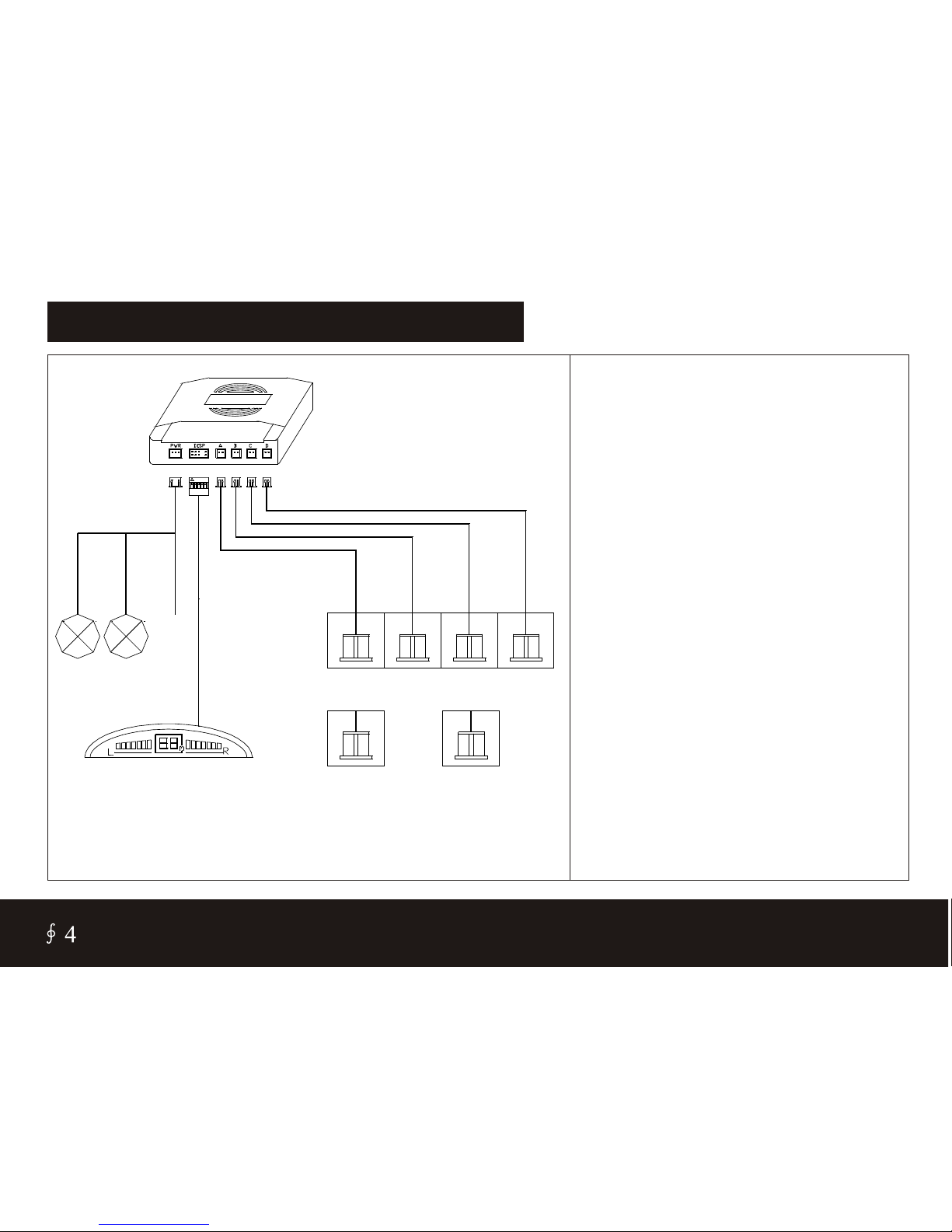
INSTALLATION FOR 2 & 4 SENSORS
1. This diagram only for 2 and
4 back sensors.
2. The system begin to work
while the car on reversing
time.
3. The display such asLED
display, LCD display, only
Buzzer, rearview mirror,
detail see Page 3.
4. The sensors will be on
flashing while the car on
brake time if the system be
Matched the illuminant sensor..
5.Power line guide:
Reversing light: Power on
while the car on reversing
time.
Stop light: poweron while
brake.
SENSOR A
SENSOR B
SENSOR C
SENSOR D
4 SENSORS
2 SENSORS
BLACK GND
Reversing
light
RED +12v
DISPLAY
MAIN BOX
INSTALL ON THE BACK BUMPER
YELLOW 12v
Stop
light
(Only for lliuminant sensor)
CISBO RADER SYSTEM USER’S MANUAL
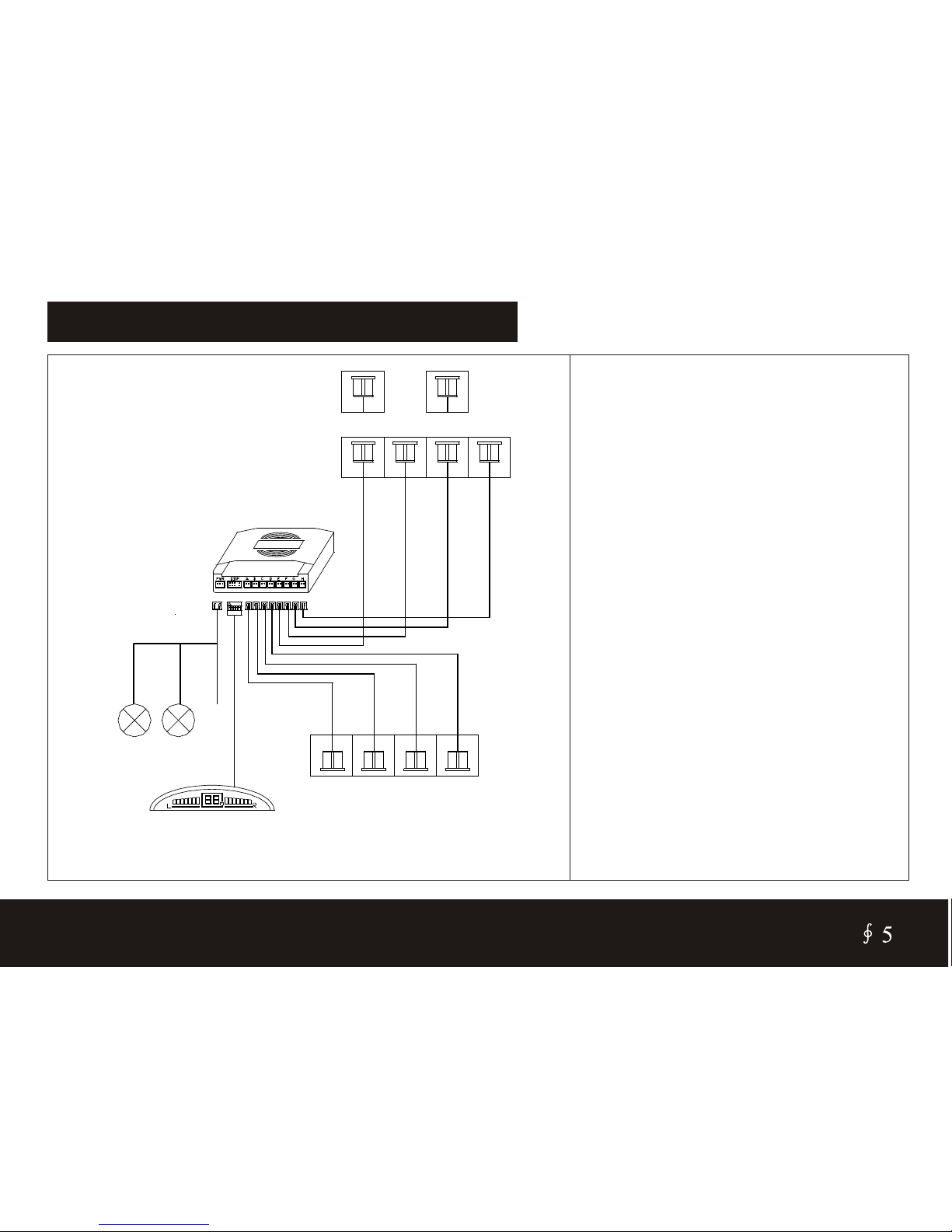
INSTALLATION FOR 6 & 8 SENSORS
1. This diagram only for 6 and
8 sensors(Front and back).
2. The front sensors begin to
work while the car onbrake
Time.
3. The back sensors begin
work while the car on
Reversing time.
4. The display such as LED
display, LCD display, only
Buzzer, rear view mirror,
detail see Page3.
5.Power line guide:
Reversing light: Power on
while the car on reversing
time.
Stop light: power on while
brake.
MAIN BOX
BLACK GND
RED +12v
YELLOW 12v
Reversing
light
Stop
light
DISPLAY INSTALL ON THE BACK BUMPER
4 SENSORS
SENSOR A
SENSOR B
SENSOR C
SENSOR D
SENSOR E
SENSOR F
SENSOR G
SENSOR H
INSTALL ON THE FRONT BUMPER
CISBO RADER SYSTEM USER’S MANUAL

INSTALLATION FOR WIRELESS TYPE
1. This diagram only for
wireless parking sensor.
2. The back sensors begin to
work while the car on
reversing time.
3.the sensors will be on
flashing while the car on
brake time if the system be
matched the illuminant
Sensor.
4. The display such as LED
display, LCD display, only
Buzzer, rear view mirror,
detail see Page 3.
5.Power line guide:
Reversing light: Power on
while the car on reversing
time.
Stop light: power on while
brake.
BLACK GND
RED +12v
YELLOW 12v
Reversing
light
Stop
light
(Only for lliuminant sensor)
4 SENSORS
2 SENSORS
MAIN BOX DISPLAY
SENSOR A
SENSOR B
SENSOR C
SENSOR D
INSTALL ON THE BACK BUMPER
TO CIGARETTE JACK +12V
BLACK GND
RED +12v
YELLOW 12v
CISBO RADER SYSTEM USER’S MANUAL
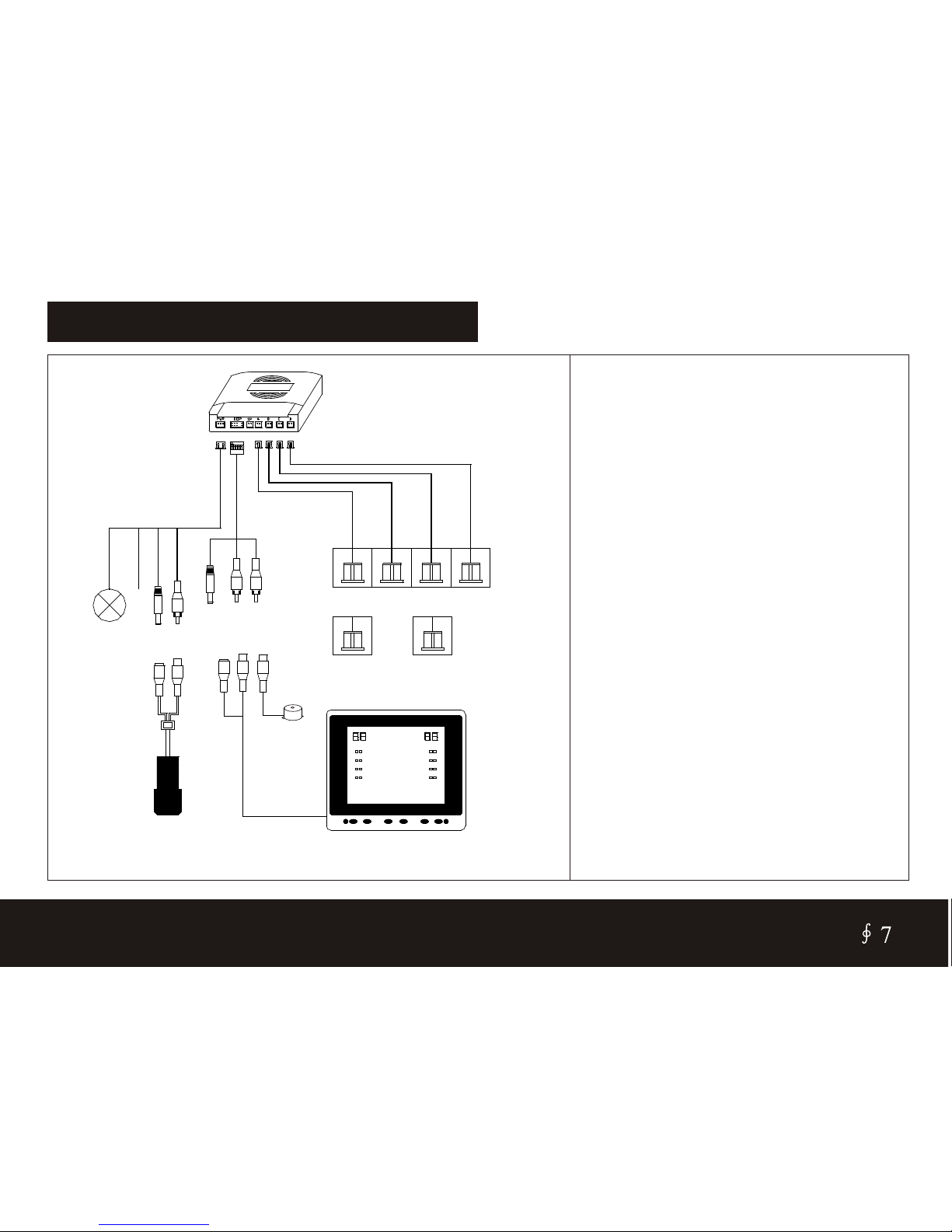
INSTALLATION FOR VIDEO TYPE
1. This diagram only for the
parking sensor with camera.
2. When the car on reversing ,
the back sensors and
camera are working.
3.The imagine will display on
the external TFT screen,
while the distance will
display as well.
4. The display is used for car
DVD/VCD.
5.Power line guide:
Reversing light: Power on
while the car on reversing
time.
Stop light: power on while
brake.
BLACK GND
RED +12v
Reversing
light
Camera
TO CAMERA
TO CAMERA
TFT Screen (optional)
DC PLUG
YELLOW VIDEO
WHITE BUZZER
BUZZER
SENSOR A
SENSOR B
SENSOR C
SENSOR D
4 SENSORS
2 SENSORS
INSTALL ON THE BACK BUMPER
INSTALL ON THE BACK BUMPER
CISBO RADER SYSTEM USER’S MANUAL
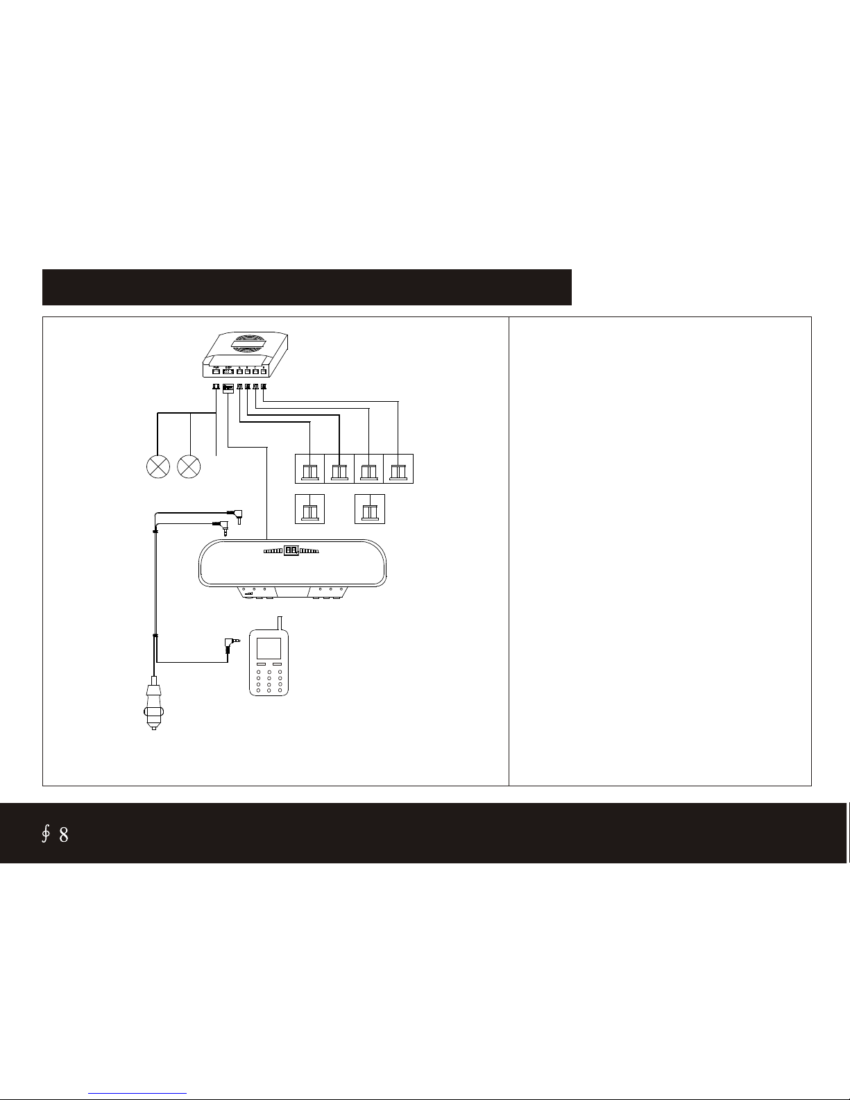
INSTALLATION FOR REARVIEW MIRROR TYPE
1. This diagram only for 4 in 1
or 6 in 1 parking sensor
2. The back sensors begin to
work while the car on
reversing time.
3.the sensors will be on
flashing while the car on
brake time if the system be
matched the illuminant
sensor.
4. The function see detail
Page 15.
5. The display clip on the
original rearview mirror.
6.Power line guide:
Reversing light: Power on
while the car on reversing
Time.
Stop light: power on while
brake.
YELLOW 12v
Reversing
light
(Only for lliuminant sensor)
INSTALL ON THE
BACK BUMPER
BLACK GND
MAIN BOX
RED +12v
Stop
light
DISPLAY
4 SENSORS
2 SENSORS
TO CIGARETTE JACK +12V
SENSOR A
SENSOR D
SENSOR C
SENSOR B
MOBILE PHONE
CISBO RADER SYSTEM USER’S MANUAL

POSITION FOR EACH PART
POSITION GUIDE:
1. 4 back sensors: Back
bumper.
2. Camera: middle of the
back bumper.
3.buzzer:back side of back
seat.
4. Main box: Back chest.
5.TFT LCD screen: amount
the sunshade board or stand
on the front board.
6. Hands free rear view mirror:
Clip on the original rearview
mirror.
7. Display: Stand on the front
board.
8.4 front sensor: front bumper.
1. 4 back sensors
4. Parking sensors
main box
3. Buzzer
7. D Isplay
6. Hands free car kit rear view mirror
8. 4 front sensors
5. TFT LCD SCREEN
2. Camera
CISBO RADER SYSTEM USER’S MANUAL

DISPLAY INSTALLATION DIAGRAM
Clean the installationposition Tearthe 3M pasterof display Install the display The cord shouldbe invisible
MAIN BOX INSTALLATION DIAGRAM
Locate the mainbox in the
rear boot ata place safeaway
from rain,heat or humidity
Lay the wiressnugy to avoid
ugly outlooking
CISBO RADER SYSTEM USER’S MANUAL
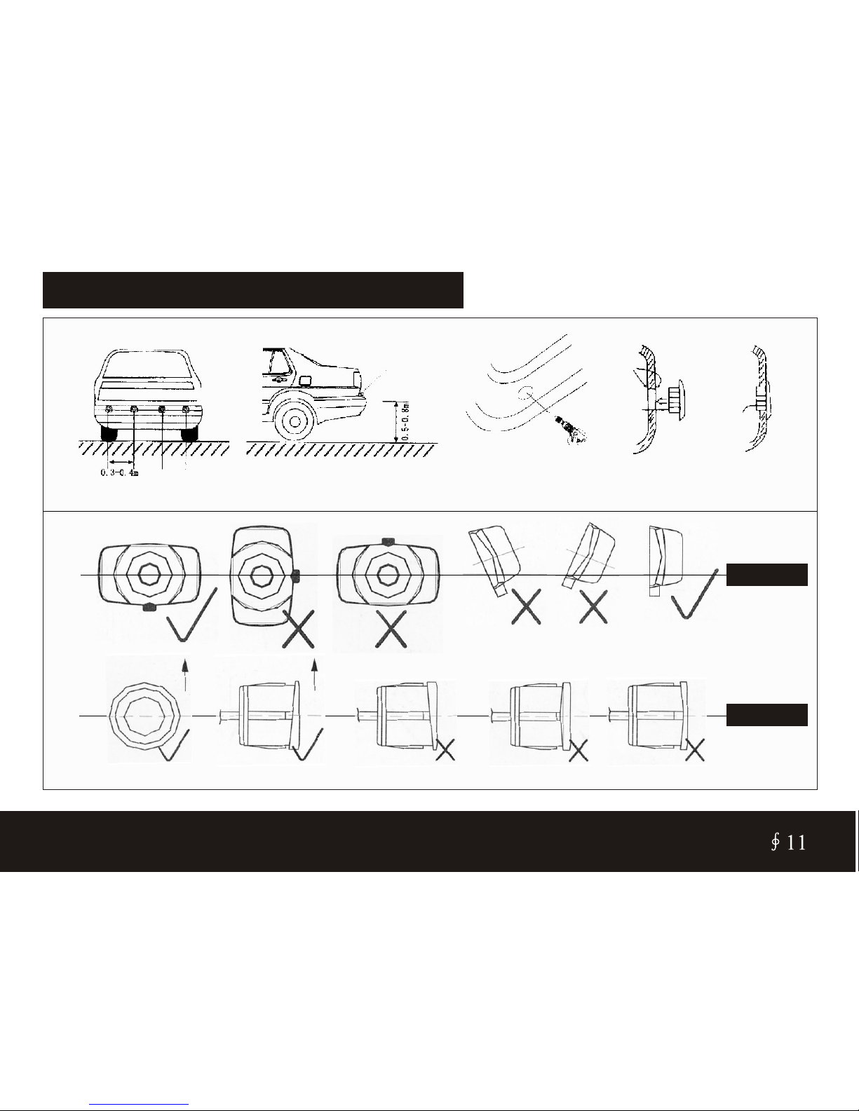
SENSORS INSTALLATION DIAGRAM
4 sonsors Bumper Driller
Sensor
Bumper
Side vision
Stick on
Insert in
CISBO RADER SYSTEM USER’S MANUAL

NOTICE FOR USER
Smooth slope Smooth round object Cotton kind barrier Rainstorm
1.Follwing situation will weaken the detectou effect
2.simple service
Trouble Trouble from Resolvent
Parking sensor doesn’t work
Power light onthe light state,
it still doesn’t work
display the samenumber
again and again
Display the wrongnumber
1.Power line connectedwrong
2.Jack connected wrong
Sensor jack connectedwrong
Sensor can’t work
Sensor detect carbody or ground
1. Jack connectedwrong
2.Sensor line maybe damaged
1. Connected thered line to+12V
2.Check each jackput the rightsocket
Re-connect sensor jack
Adjust the sensorposition and angle
1.Power off,then refreshall jack
2.Check the sensorline, be sureit doesn’t
be closed withvent-pipe or silencer
CISBO RADER SYSTEM USER’S MANUAL
FUNCTIONS FOR LED DISPLAY SERIES
CISBO RADER SYSTEM USER’S MANUAL
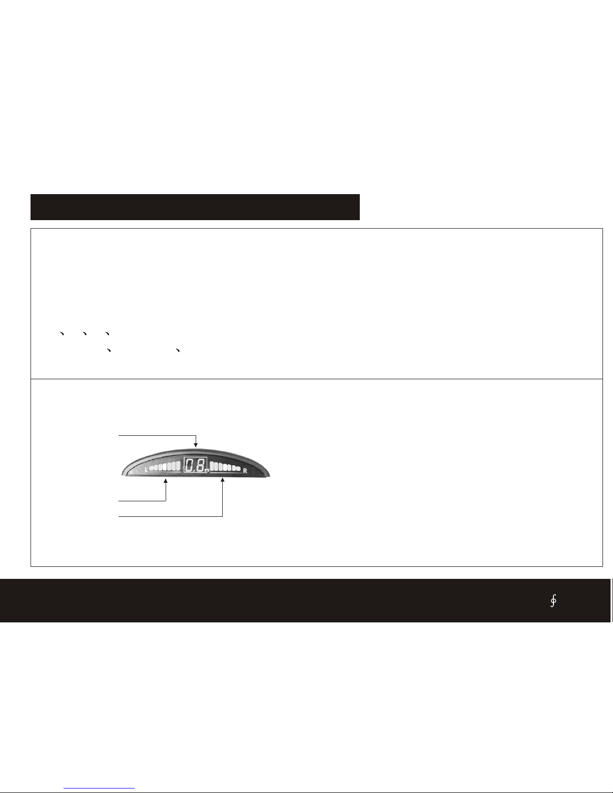
1. LED display :It is for model such as: SB303(F) ,SB305,SB306(F).SB323(F)
2.
3.
4.
5.
8. If no needthe LED display, there areBuzzer only canbe replaced
Digital LED showingobstacle distance
Alarm by three step Bi-Bi sound
LED display with two side indicate.
Crescent shape digitaldisplay screen
6. 2 4 6 8 sensors areavailable.
7. Insert in Stick on illuminate sensors areavailable.
2. Indicate left
1. Indicate right
3. Distance
1.Indicate left-- Whenthe back left sensordetect the obstacle, itwill
glitter.
2.Indicate right- Whenthe back right sensordetect the obstacle, itwill
glitter.
3. Distance-Display the latestthe distance for allsensors.
13

CISBO RADER SYSTEM USER’S MANUAL
FUNCTIONS FOR LCD DISPLAY SERIES
1. L CD display :It is for model such as: SB308(F) ,SB309(F)
2.
3.
Digital LCD showing obstacle distance
Alarm by three step Bi-Bi sound
4. Colourized LCD screen or blue colour background
5. The simulative vehicle is displayed in the colourized screen
6. 2 4 6 8 sensors are available.
7. Insert in Stick on illuminate sensors are available.
2.Indicate back-left
1. Indicate back-right
4.Indicate front-left
5.Indicate front-right
3.Simulate car
7.Simulate bar
6.Bracket
9.Distance
10.Background
8.Voice switch
1.Indicate back right-When the back rightsensor detect the obstacle,it
will glitter.
2.Indicate back left-When the back leftsensor detect the obstacle,it will
glitter.
3.Simulate car-When reversingthe car, itwill show on thescreen.
4.Indicate front left-When the front leftsensor detect the obstacle,it will
glitter.
5.Indicate front right- Whenthe front right sensordetect the obstacle, it
will glitter.
6.Bracket-You canturn over the screen.
7. Simulate bar-When the obstacleis closer, thebar will more andmore.
8.Voiceswitch- Turn on/off the voice.
9. Distance-Display the latestthe distance for allsensors.
10. Background- Blue background.
14
1. Mic
2. Volume control
3.ON/OFF
4.Stand by 5.Earphone jack
6.Record
7.Play
8.Mute
Mic volume adjustor
Aecho adjustor
10.Signal input jack
9.Power input jack
11.Speaker
12.Indicate right
13.Distance
14.Indicate left
CISBO RADER SYSTEM USER’S MANUAL
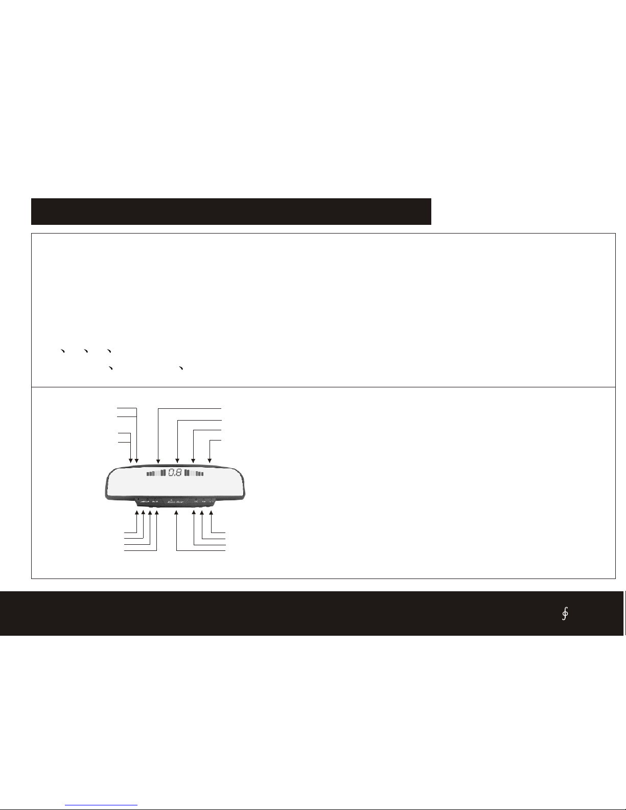
FUNCTIONS FOR REARVIEW DISPLAY SERIES
1. LED display :It is for model such as: SB808(F) ,SB818(F)
2.
3.
Digital LED showingobstacle distance
Alarm by three step Bi-Bi sound
4. Rear view mirror with Guarding against dizzy light and fog function
5. Hans freecar kit
6. With Record, play, mute function
7. 2 4 6 8 sensors areavailable.
8. Insert in Stick on illuminate sensors are available.
1.Mic - Used toreceive voice from user.
2.VolumeControl- Used to controlthe speaker volume level.
3.ON/OFF-ppower On and Off.When ON/OFF LED lit,the system is
work.
4Standby - For somemobile phone system, youcan press Standby button
to receive your call(forCDMA system only).
5.Earphone Output jack- Forprivate listening of thecall.
6.Record Button- Used torecord message.
7.Play Button- Used toplay back all recordedmessage.
8.Mute Button- Used toturn off themicrophone of MOBILE MIRROR.
9.Power Input Jack -Accepts input plugfrom car power cord.
10.Hand Free Input Jack- Accepts inputplug from hand freecord .
11.Speaker- the phonevoice will be directedthrough this Speaker.
12.Indicate right- Whenthe back right sensordetect the obstacle, itwill
light.
13.Distance- Display the latestthe distance for allsensors.
14.Indicate left- Whenthe back left sensordetect the obstacle, itwill
light.
15
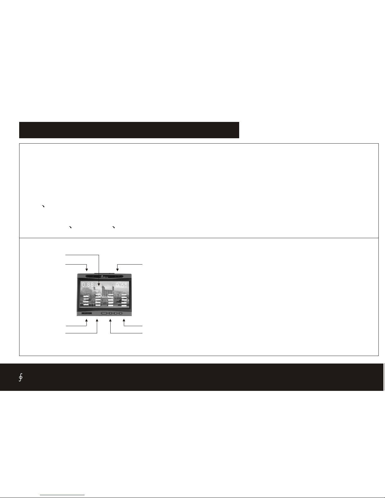
FUNCTIONS FOR VIDEO DISPLAY SERIES
1. TFTLCD display :It is for model: SB838(F) ,SB868(F)
2. TFT
3.
4.
LCD displays the practical image behind your car when reversing
Two series numbers displaythe distances
Alarm by three step Bi-Bi sound
5. The simulative vehicle isdisplayed in thecolourized screen
6. 2 4 sensors areavailable.
7. Withcamera.
8. Insert in Stick on illuminate sensors are available.
7.Right distance
3.Simulate Bar
1.Image
5.Simulate Bar
6.Simulate Bar
4.Simulate Bar
2. Left distance
1.Image- Display the rear image by Camera
2.left distance- display theobstacle distance for backleft 2 sensors
3.simulate Bar -Indicate theback-left sensor working state,When the
obstacle is closer,the bar will moreand more.
4.simulate Bar -Indicate theback-left-middle sensor working state,
When the obstacle iscloser, the barwill more and more.
5.simulate Bar -Indicate theback-right-middle sensor working state,
When the obstacle iscloser, the barwill more and more.
6.simulate Bar -Indicate theback-right sensor working state,When the
obstacle is closer,the bar will moreand more.
7.Right distance- display theobstacle distance for backright 2 sensors
CISBO RADER SYSTEM USER’S MANUAL
16

GUARANTEE FORM CISBO
GUARANTEE FORM
Model Number
Date of purchase:
Customer’s name
Telephone
Car registration Number
Stamp/signature of dealer:
Note:
1.Guarantee time:12months.
2.The guarantee will be effedtive with the stamp/sugnature of
the dealer.
3.Please keep the guarantee form well to ensure 12 months
guarantee.
CISBO RADER SYSTEM USER’S MANUAL
17

Table of contents
Popular Automobile Accessories manuals by other brands


Cruz
Cruz 941-556 Assembly instructions

Crux
Crux Sightline RVCAD-81B Guideline

Toyota
Toyota DVR owner's manual

Extreme marquees
Extreme marquees DESERT SHADE 90 instruction manual

Stromberg Carlson Products
Stromberg Carlson Products CC-255 installation instructions

Metra Electronics
Metra Electronics 99-7506 installation instructions


