manuals.online logo
Brands
  1. Home
  2. •
  3. Brands
  4. •
  5. Stromberg Carlson Products
  6. •
  7. Automobile Accessories
  8. •
  9. Stromberg Carlson Products CC-255 User manual

Stromberg Carlson Products CC-255 User manual

StrombergCarlson.com • 231.947.8600
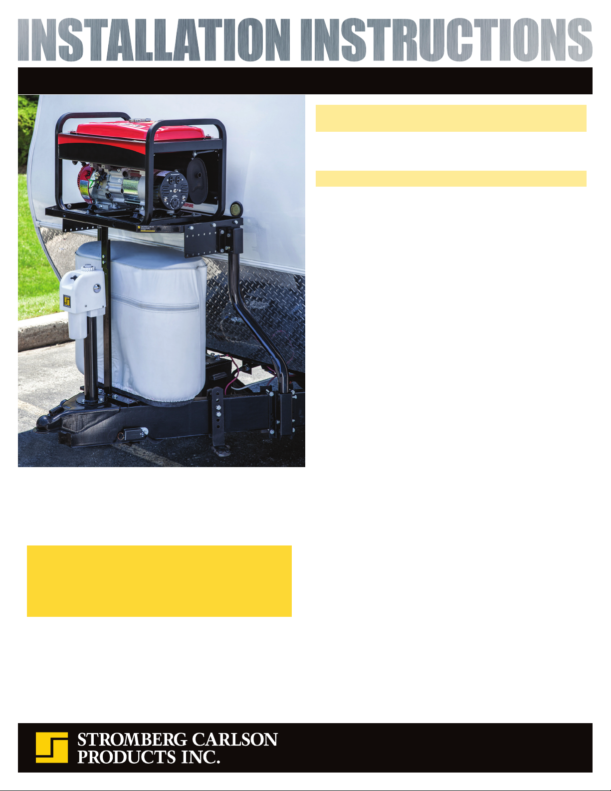
Please read all directions prior to installation. The Trailer
Tray may not work on all trailers. Confirm fit and clearance
prior to drilling any holes. Installation takes approximately
1 hour, and should be a 2-person project, due to the sturdy
construction and weight of the tray itself.
INS-CC255-C 06.17.2021
Trailer Tray
Model: CC-255 Patent Pending
Trailer Tongue Mounted Trailer Tray CC-255 Patent Pending
Check the frame pocket mounting locations for interferences
such as wiring, battery, battery tray, equalizer brackets, etc. Most
of these items can be relocated or reinstalled after the frame
pockets are installed, as the pockets do not take up much space.
If you have propane tanks installed at the intended tray location,
one of three things can be done to allow you to remove your
tanks for refill or to access valves without removing the tray.
1. Replace your tank cover with a soft vinyl cover, allowing you to
access valves or to remove tanks without tray removal.
2. Replace your tank cover with a flip top hard plastic cover to
access your valves. You will still need to remove the tray to
remove cover and refill LP tanks.
3. Leave the tank cover off for direct access to your tanks.
Installation Instructions
Mount lower pockets (Figure F) and lower pocket back plates
(Figure G) on your trailer frame (loosely, so adjustments can be
made later) using 5/16” x 4” hardware (Figure K).
 Make sure the pockets are about 2”- 3” from trailer body.
 Mount pockets on the outside of trailer frame and back
plates on inside of trailer frame, as shown on page 2.
 Bolts can be installed in either direction. Secure through the
holes that are most close-fitting to your trailer frame top and
bottom edge.
Attach the trailer tray plates (Figure I) to the sides of the trailer tray
(Figure A), using 3/8” x 3/4” hardware (Figure M).
Loosely attach the upper pockets (Figure E) to the trailer tray
plates, using 5/16” x 1” hardware (Figure L).
Insert either end of the vertical tubes (Figure B) into the frame
pockets. With a second person stabilizing the tray, rotate the
vertical tubes to allow the upper pockets to slide onto the tubes.
If necessary, adjust the upper pocket location on the trailer tray
plates so the tray is 1”- 2” away from your trailer’s front wall and
tighten attachment hardware.
Secure vertical tubes in the upper and lower pockets using
provided hardware (Figures N and O), as shown on page 2.
 Drill 3/8” holes through the vertical tubes for this hardware,
once you verify turn radius/clearance.
 For accuracy purposes, we suggest you mark hole locations
and remove the tubes from the assembly prior to drilling.
Drill through each tube halfway only, then from the other
side halfway. Reassemble and tighten hardware, checking
that the trailer tray is still 1”- 2” from the front trailer wall.
Sandwiching your frame, connect the lower mount (Figure H) to
the lower support mount (Figure D) using 5/16” x 8” hardware
(Figure J). Attach loosely, to allow for adjustment.
Attach upper support mount (Figure C) and lower support mount
(Figure D) using 5/16” x 1” hardware (Figure L).
Attach upper support mount to trailer tray (Figure A) using
5/16” x 1” hardware (Figure L), adjusting lower mount location to
allow for proper attachment. Tighten all hardware.
Please note, the tray has several tie-down eyelets on the edges and
numerous holes in the tray top to secure your cargo.
*DOUBLE CHECK ALL HARDWARE IS SECURE PRIOR TO TRAVEL*
Thank you for purchasing the first trailer tongue cargo carrying
system by Stromberg Carlson.
Trailer Tongue Mounted Trailer Tray CC-255 Patent Pending
Vertical C-Channel Tube (x2)
Lower Pocket (x2)
Upper Support Mount (x1)
Lower Pocket Back Plate (x4))
Lower Support Mount (x1)
Lower Mount (x1)
Upper Pocket (x2)
Trailer Tray Plate (x2)
5/16” x 8” (2) 5/16” x 4” (8) 5/16” x 1” (12) 3/8” x 3/4” (6) 3/8” x 2-1/2” (4) 3/8” x 1” Set Screw (4)
Replacement part number for all nut and bolt hardware shown below (Figures J, K, L, M, N, O) is #2155
Trailer Tray
Carton Contents
Model: CC-255
Patent Pending C
A
E
N
O
F
O
N
B
I
H G
D
FIGURE B (#7605-107P) FIGURE C (#7605-115) FIGURE D (#7605-120) FIGURE E (#7605-106P)
FIGURE F (#7605-104P) FIGURE G (#7605-117) FIGURE H (#7605-118) FIGURE I (#7605-102P)
Trailer Tray (x1)
DIMENSIONS ARE APPROXIMATE
14.243”
7.052”
20.159”
32.375”
24.785”
FIGURE A (#7605-101P)
FIGURE J FIGURE K FIGURE L FIGURE M FIGURE N FIGURE O

Other Stromberg Carlson Products Automobile Accessories manuals

Stromberg Carlson Products BC-104 User manual

Stromberg Carlson Products

Stromberg Carlson Products BC-104 User manual

Stromberg Carlson Products CC-255 User manual

Stromberg Carlson Products

Stromberg Carlson Products CC-255 User manual

Stromberg Carlson Products BC-202 User manual

Stromberg Carlson Products

Stromberg Carlson Products BC-202 User manual

Stromberg Carlson Products LA-401 User manual

Stromberg Carlson Products

Stromberg Carlson Products LA-401 User manual

Stromberg Carlson Products BC-204 User manual

Stromberg Carlson Products

Stromberg Carlson Products BC-204 User manual

Stromberg Carlson Products CC-275 User manual

Stromberg Carlson Products

Stromberg Carlson Products CC-275 User manual

Stromberg Carlson Products BC-204 User manual

Stromberg Carlson Products

Stromberg Carlson Products BC-204 User manual

Popular Automobile Accessories manuals by other brands

Magneti Marelli AC161 Installation instruction

Magneti Marelli

Magneti Marelli AC161 Installation instruction

FDI uEZ GUI Start here

FDI

FDI uEZ GUI Start here

JCROffroad JT Install instructions

JCROffroad

JCROffroad JT Install instructions

Rostra VOXXElectronics 250-1930 owner's guide

Rostra

Rostra VOXXElectronics 250-1930 owner's guide

TOP VEHICLE TECH GR3FORD5 installation manual

TOP VEHICLE TECH

TOP VEHICLE TECH GR3FORD5 installation manual

Safe Fleet PRIME DESIGN AR-2000-BLK manual

Safe Fleet

Safe Fleet PRIME DESIGN AR-2000-BLK manual

Skoda Fabia Combi 5J Fitting instructions

Skoda

Skoda Fabia Combi 5J Fitting instructions

Camcar 40077 Al Mounting instructions

Camcar

Camcar 40077 Al Mounting instructions

Camcar 40089 AL Mounting instructions

Camcar

Camcar 40089 AL Mounting instructions

Impac Tradesman 2000 installation manual

Impac

Impac Tradesman 2000 installation manual

DVB OFFROAD BRSB-01 installation manual

DVB

DVB OFFROAD BRSB-01 installation manual

Safari Snorkel SS385HF installation guide

Safari Snorkel

Safari Snorkel SS385HF installation guide

ULTIMATE SPEED 279746 Assembly and Safety Advice

ULTIMATE SPEED

ULTIMATE SPEED 279746 Assembly and Safety Advice

SSV Works DF-F65 manual

SSV Works

SSV Works DF-F65 manual

ULTIMATE SPEED CARBON Assembly and Safety Advice

ULTIMATE SPEED

ULTIMATE SPEED CARBON Assembly and Safety Advice

Witter F174 Fitting instructions

Witter

Witter F174 Fitting instructions

WeatherTech No-Drill installation instructions

WeatherTech

WeatherTech No-Drill installation instructions

TAUBENREUTHER 1-336050 Installation instruction

TAUBENREUTHER

TAUBENREUTHER 1-336050 Installation instruction

manuals.online logo
manuals.online logoBrands
  • About & Mission
  • Contact us
  • Privacy Policy
  • Terms and Conditions

Copyright 2025 Manuals.Online. All Rights Reserved.