Cisco kids Autronic SM2 User manual

Autronic SM2 Manual ver 1.6
1
TABLE OF CONTENTS
INTRODUCTION .........................................................................................................................4
BEFORE YOU BEGIN ....................................................................................................................4
SOFTWARE. ...............................................................................................................................5
PC HARDWARE REQUIREMENTS....................................................................................................5
SOFTWARE INSTALLATION WINDOWS SOFTWARE. ..........................................................................5
SOFTWARE INSTALLATION MS-DOS SOFTWARE............................................................................6
GENERAL KEYS ...........................................................................................................................7
EDIT KEYS...................................................................................................................................7
AUTOTUNE™KEYS (ECU’S WITH 1.90 OR HIGHER CHIP VERSIONS) ................................................7
DATA LOGGING KEYS...................................................................................................................7
SOFTWARE INTERFACE AND MENUS..............................................................................................8
MODE FLAGS..............................................................................................................................9
SOFTWARE TABLES. ..................................................................................................................10
BASIC SOFTWARE SETUP. ....................................................................................................11
BASE SETTINGS. .......................................................................................................................11
ENGINE SETUP..........................................................................................................................12
INJECTOR SELECTION.................................................................................................................13
BASE FUEL DELIVERY................................................................................................................13
BASE IGNITION TIMING...............................................................................................................14
RELAY/ANALOG O/P..................................................................................................................16
HARDWARE SETUP.................................................................................................................17
WIRING NOTES..........................................................................................................................17
MAIN WIRING DIAGRAM...............................................................................................................18
RELUCTOR INTERFACE (REQUIRED FOR INDUCTIVE SENSORS) .......................................................19
CRANK TRIGGER WIRING WITH HALL EFFECT SENSORS..................................................................20
CRANK TRIGGER WIRING WITH MAGNETIC SENSORS......................................................................21
NO1SPARK PLUG REFERENCE SENSOR WITH HALL EFFECT DISTRIBUTOR.......................................22
NO1SPARK PLUG REFERENCE SENSOR WITH RELUCTOR INTERFACE .............................................23
IGNITION SETUP 4-CYL,2X DOUBLE ENDED COILS (BOSCH 008 MODULES).....................................24
IGNITION SETUP 6-CYL,3X DOUBLE ENDED COILS (BOSCH 008 MODULES).....................................25
IGNITION SETUP 8-CYL,4X DOUBLE ENDED COILS (BOSCH 008 MODULES).....................................26
IGNITION SETUP 4-CYL,4X SINGLE COILS (R500 CDI).................................................................27
IGNITION SETUP 6-CYL,6X SINGLE COILS (R500 CDI).................................................................28
IGNITION SETUP 8-CYL,8X SINGLE COILS (R500 CDI).................................................................29
IGNITION SETUP 4-CYL,2X DOUBLE ENDED COILS (R500 CDI).....................................................30
IGNITION SETUP 6-CYL,3X DOUBLE ENDED COILS (R500 CDI).....................................................31
IGNITION SETUP 8-CYL,4X DOUBLE ENDED COILS (R500 CDI).....................................................32
DIRECT FIRE CDI......................................................................................................................33
C
I
S
C
O
K
I
D
S
P
A
R
T
S
P
R
O
J
E
C
T
W
W
W
.
C
I
S
C
O
K
I
D
S
.
C
O
M
.
A
U

Autronic SM2 Manual ver 1.6
2
THROTTLE POSITION SENSOR (TPS). ..........................................................................................34
WATER TEMPERATURE SENSOR..................................................................................................34
AIR TEMPERATURE SENSOR........................................................................................................34
TRIGGER SETUP FOR DISTRIBUTORS...........................................................................................35
CRANKSHAFT AND CAMSHAFT TRIGGER SETUP WITH HALL EFFECT SENSOR..................................36
CRANKSHAFT AND CAMSHAFT TRIGGER SETUP WITH MAGNETIC-RELUCTOR SENSOR.......................38
IGNITION SETUP OUTPUT SEQUENCE ..........................................................................................40
DATALOGGING SETUP,WIRING ....................................................................................................41
SENSORS .................................................................................................................................43
COOLANT TEMPERATURE SENSOR..............................................................................................43
AIR TEMPERATURE SENSOR.......................................................................................................43
THROTTLE POSITION SENSOR SETUP (TPS)................................................................................44
THROTTLE LIMIT LEARNING ........................................................................................................44
ADVANCED SOFTWARE SETUP ............................................................................................45
BOOST CONTROL VALVE (INTERNAL WASTEGATE)........................................................................45
BOOST CONTROL VALVE (EXTERNAL WASTEGATE).......................................................................46
CLOSED LOOP CONTROL ...........................................................................................................47
IDLE VALVE SETUP SM2............................................................................................................48
TURBOCHARGER ANTI-LAG SYSTEM ...........................................................................................50
TRACTION CONTROL SETUP .......................................................................................................53
MISSING TEETH CRANK TRIGGER SETUP.....................................................................................55
THROTTLE/MANIFOLD MAPPING. .................................................................................................56
AUTOTUNE™ ...........................................................................................................................57
SOFTWARE SETUP.....................................................................................................................57
HARDWARE SETUP.....................................................................................................................58
RUNNING AUTOTUNE™..............................................................................................................60
STARTING THE ENGINE FOR THE FIRST TIME. ...................................................................61
ITEMS REQUIRED. ......................................................................................................................61
SOFTWARE. ..............................................................................................................................61
STARTING THE ENGINE...............................................................................................................61
DIRECT FIRE IGNITION SEQUENCE TESTING...................................................................................62
SOFTWARE TABLES DESCRIPTION......................................................................................63
BASE FUEL DELIVERY CALIBRATION............................................................................................63
BASE IGNITION TIMING CALIBRATION...........................................................................................63
OVERRUN IGNITION TIMING CALIBRATION ....................................................................................63
CRANKING IGNITION TIMING........................................................................................................63
IDLING IGNITION TIMING CALIBRATION .........................................................................................63
COOLANT IGNITION TIMING MODIFIER CALIBRATION......................................................................63
ALTITUDE IGNITION TIMING MODIFIER CALIBRATION ......................................................................63
FUEL INJECTION DELIVERY TIMING..............................................................................................64
INDIVIDUAL CYLINDER FUEL DELIVERY TRIMMING.........................................................................64
MANIFOLD ABSOLUTE PRESSURE SENSOR FAILURE LIMP HOME CALIBRATION................................64
THROTTLE POSITION SENSOR FAILURE LIMP HOME CALIBRATION..................................................64
EXHAUST BACK PRESSURE SENSOR FAILURE LIMP HOME CALIBRATION ........................................64
C
I
S
C
O
K
I
D
S
P
A
R
T
S
P
R
O
J
E
C
T
W
W
W
.
C
I
S
C
O
K
I
D
S
.
C
O
M
.
A
U

Autronic SM2 Manual ver 1.6
3
TRANSIENT ENGINE OPERATION CALIBRATION.............................................................................64
CHARGE TEMPERATURE ESTIMATION CALIBRATION......................................................................65
WARM-UP ENRICHMENT ............................................................................................................65
POST START ENRICHMENT CALIBRATION.....................................................................................65
POST START ENRICHMENT TIMEOUT CALIBRATION.......................................................................65
WARM-UP ACCELERATION ENRICHMENT MULTIPLIER ...................................................................65
WARM-UP FAST IDLE RPM CALIBRATION.....................................................................................66
POST START FAST IDLE RPM CALIBRATION..................................................................................66
POST START FAST IDLE RPM TIMEOUT CALIBRATION....................................................................66
WASTEGATE CONTROL ..............................................................................................................66
ENGINE SPEED LIMIT .................................................................................................................67
OVERRUN FUEL DELIVERY CUT OFF ...........................................................................................67
BASE IDLE SPEED CONTROL CALIBRATION...................................................................................67
USER DEFINED DUTY RATIO OUTPUT CALIBRATION......................................................................67
USER DEFINED ON/OFF OUTPUT CALIBRATION............................................................................67
IDLE MIXTURE CONTROL RANGE CALIBRATION .............................................................................67
BAROMETRIC PRESSURE ESTIMATION OFFSET CALIBRATION ........................................................67
OPEN LOOP AIR-FUEL RATIO CALIBRATION..................................................................................68
MISCELLANEOUS CALIBRATION ...................................................................................................68
ECU DIAGNOSTIC....................................................................................................................70
ERROR INDICATOR LIGHT ...........................................................................................................70
ERROR WARNING /DIAGNOSTIC LIGHT FAULT CODES ..................................................................71
EXAMPLE OF ERROR INDICATION .................................................................................................72
MODE FLAGS...........................................................................................................................73
SM2 V1.07 MODE FLAGS..........................................................................................................73
SM2 V1.34-V1.35 MODE FLAGS ...............................................................................................76
SM2 V1.37 MODE FLAGS ..........................................................................................................81
SM2 V1.49 MODE FLAGS (ROTARY &SECOND REV.LIMIT CHIP)...................................................86
SM2 V 1.91 MODE FLAGS (AUTOTUNE)......................................................................................92
SM2 V 1.92 MODE FLAGS (FLAT SHIFT ).....................................................................................97
C
I
S
C
O
K
I
D
S
P
A
R
T
S
P
R
O
J
E
C
T
W
W
W
.
C
I
S
C
O
K
I
D
S
.
C
O
M
.
A
U

Autronic SM2 Manual ver 1.6
4
Introduction
Congratulations on your decision to install an Autronic engine management system to your
vehicle. Autronic systems have been successfully installed on many vehicles such as rally cars,
off road vehicles, street cars, powerboats, offshore powerboats, and in other forms of racing.
Autronic is designed to enable users to precisely control ignition timing and fuel-air mixture.
Precise ignition and mixture control also leads to excellent drivability and fuel economy -
something that is often lacking in high-performance carburettor engines.
Before You Begin
1) READ THIS ENTIRE MANUAL BEFORE STARTING.
The greater your knowledge of the operation of the Autronic ECU, the easier you will find it to
understand what you are doing, and why.
2) Read any additional material accompanying this manual that updates the document since it
was written.
3) You may need special parts or additional tools or test equipment in order to complete
installation. Make sure you have these items on hand before you begin to avoid frustration.
Contact your Autronic dealer if you have difficulty.
4) Do not take any shortcuts. Mistakes in the early stages of installation can cause you major
headaches later on, be it in a few days or a few months time. Mistakes or shortcuts will cost you
money and frustration in finding and fixing unnecessary problems. You have the opportunity to
make your Autronic´s ECU operation extremely dependable and easy to use by doing it right the
first time.
Avoid open sparks, flames, or operation of electrical devices near flammable
substances.
Always disconnect the Battery cables when doing electrical work on your vehicle.
All fuel system components and wiring should be mounted away from heat
sources, shielded if necessary, and well vented.
Make sure there are no leaks in the fuel system and that all connections are
secure.
Disconnect the Autronic ECU from the electrical system whenever doing any arc
welding on the vehicle by unplugging the wiring harness connector from the ECU.
C
I
S
C
O
K
I
D
S
P
A
R
T
S
P
R
O
J
E
C
T
W
W
W
.
C
I
S
C
O
K
I
D
S
.
C
O
M
.
A
U

Autronic SM2 Manual ver 1.6
5
Software.
PC hardware requirements.
The calibration and data logging software supplied with Autronic SMC ECU may be used with
computers operating under Windows 95/98/ME/XP or 2000.
Computer Required Hardware
The computer must have the following hardware
•VGA graphics adaptor (or compatible adaptors).
•Minimum of 2MB random accesses memory.
•One serial communication port, or USB port and serial to USB adaptor (Windows
software only).
•One 3.5" floppy disk drive.
The following functions are available using this program:-
1. Real-time display of the current operating status of the ECU and engine.
2. Display of error/fault condition history information recorded in the ECU and the
cancellation of stored error history.
3. Display of the relative timing of the engine position reference signals for ease of
setup.
4. Setup of ECU data logging.
5. Data logging using PC memory.
6. Display of logged ECU or PC memory data.
Calibration Adjustment:-
•Non-interactive calibration of the ECU. (Off-line calibration editing).
•Interactive calibration of the ECU (online calibration editing).
•Disk file storage and retrieval of calibrations.
•Free transfer of calibrations between file, screen and ECU.
•Calibration process does not effect normal ECU operation ie:- No hiccups during online
adjustment.
•Calibration may be password secured in ECU to prevent unauthorised access.
•User ID may be included with calibration in ECU when required.
C
I
S
C
O
K
I
D
S
P
A
R
T
S
P
R
O
J
E
C
T
W
W
W
.
C
I
S
C
O
K
I
D
S
.
C
O
M
.
A
U

Autronic SM2 Manual ver 1.6
6
Software installation Windows Software.
Step 1. Start Windows
Step 2. Place floppy disk in A: drive.
Step 3 Click on the “Start” button and then click on “Browse”.
Step 4 Select the A: drive and double click the file on the A drive.
Step 5. Click the OK button.
Step 6. Read the options displayed and click the “Next” buttons to complete the installation.
Step 7. Double click on the icon on the desktop to run the software.
Software Installation MS-DOS Software.
Step 1. Start Windows
Step 2. Place floppy disk in A: drive.
Step 3. Click “Start” and then “Run” Type A:\INSTALL.EXE and Click “Ok”.
Step 4 Select version to install and press Enter.
Step 5. Select “Complete Installation” and press Enter.
Step 6. Press Enter again to start the installation. After Installation is complete, select Exit and
press Enter.
Step 7. Double click on the icon on the desktop to run the software.
C
I
S
C
O
K
I
D
S
P
A
R
T
S
P
R
O
J
E
C
T
W
W
W
.
C
I
S
C
O
K
I
D
S
.
C
O
M
.
A
U

Autronic SM2 Manual ver 1.6
7
General keys
Esc ……………………….Opens or closes, menus.
Tab………………………..Next item.
Alt + menu letter…………Opens menu.
Q…………………………..Closes windows.
Space……………………..Find a site, places the curser at the current site.
Page Up…………………..Previous table.
Page Down……………….Next table.
Ctrl + F10…………………Base fuel table.
Shift + F10………………..Base ignition table.
G…………………………...Displays table in 3D graph.
Alt + X……………………..Exits the program.
F1………………………….Help
F2………………………….Saves the current file.
F3………………………….Go online to ECU.
F4………………………….Lock (store) changes into ECU.
Edit keys.
Enter………………………Type a new value into a table.
=……………………………Make small increases in table value.
-……………………………Make small decreases in table value.
Shift + +…………………...Make large increases in table value.
Shift + -……………………Make large decreases in table value.
Delete……………………..Delete a axis value (e.g:- RPM or Load axis value)
Insert………………………Insert a axis value (e.g:- RPM or Load axis value)
E…………………………...Edit axis value.
Shift + Right………………Copies a site value to the right of current site.
Shift + Left..………………Copies a site value to the left of current site.
Shift + UP...………………Copies a site value to the above site.
Shift + Down..……………Copies a site value to the site below.
Autotune™ keys (ECU’s with 1.90 or higher chip versions)
F5………………………….Run or stop Autotune.
C……………………………Course tune.
F……………………………Fine tune.
R…………………………...Remove attribute.
A……………………………Set user attribute.
Ctrl + K…………………….Copy row attribute.
Ctrl + M……………………Copy Column attribute.
Ctrl + K…………………….Show attribute.
Data Logging keys.
F8…………………………..Starts and stops PC logger.
F10…………………………Graph logged data.
Z or Arrow Up……………..Zoom in on graphed data.
C
I
S
C
O
K
I
D
S
P
A
R
T
S
P
R
O
J
E
C
T
W
W
W
.
C
I
S
C
O
K
I
D
S
.
C
O
M
.
A
U

Autronic SM2 Manual ver 1.6
8
Software Interface and Menus
The options available under menu “Edit-Window” will change depending on which table or
window is displayed. Always check this menu for possible options. Some of the hot keys on the
previous page will only be available when certain tables or windows are displayed.
Example:- The setup options for Autotune are only visible in the Edit-Window menu when the
Base Fuel Delivery table is displayed.
The drop down menus can be selected by pressing the ESC key or by pressing Alt + the
underscored letter of the menu item. e.g:- Alt + 1 will open the M1menu.
Real time display of engine parameters are displayed below open tables. The items displayed
can be selected from the “PC Limits/Log setup” under the “Logger” menu.
The User ID/Error bar will turn red and display any error or engine parameters outside the limits
set in the “PC Limits/Log setup” under the “Logger” menu. These limits can be set so you do not
have to monitor engine parameters while tuning for example, as the Software will do this for
you.
C
I
S
C
O
K
I
D
S
P
A
R
T
S
P
R
O
J
E
C
T
W
W
W
.
C
I
S
C
O
K
I
D
S
.
C
O
M
.
A
U

Autronic SM2 Manual ver 1.6
9
Mode Flags.
Autronic ECU use mode flags to select functions not selectable from the software menus.
In this example we will set mode flag 1. Setting mode flag 1 can be done in the software by
selecting from items in the menus and it is not necessary to do the settings via the mode flags
but for this example we will do it this way.
The example engine has the following,
Number of ignition coils 1
Ignition amplifier MSD (CDI ignition)
Cylinder Reference signal -ve (falling signal)
Cylinder pulse signal +ve (rising signal)
Using mode flag 1 information below we can find the value required is 49.
Function Value Flag Value
Ignition Coils 1 1
Ignition Amplifier MSD 32
Cylinder Reference signal Falling signal 16
Cylinder Pulse signal Rising signal 0
Mode Flag 1 = 49
1 1 COIL IGNITION SYSTEM 1
2 COIL IGNITION SYSTEM 2
3 COIL IGNITION SYSTEM 3
4 COIL IGNITION SYSTEM 4
1 NEGATIVE TRIGGERED IGNITION ADD 0
AMPLIFIER (MODULE) eg:- Bosch HEI
1 POSITIVE TRIGGERED IGNITION ADD 32
AMPLIFIER (MODULE) eg:- MSD
1 CYLINDER REFERENCE PULSE INPUT ADD 0
POSITIVE (RISING SIGNAL) TRIGGERED
1 CYLINDER REFERENCE PULSE INPUT ADD 16
NEGATIVE (FALLING SIGNAL) TRIGGERED.
1 CYLINDER PULSE INPUT ADD 0
POSITIVE (RISING SIGNAL) TRIGGERED.
1 CYLINDER PULSE INPUT ADD 64
NEGATIVE (FALLING SIGNAL) TRIGGERED.
1 CYLINDER PULSE INPUT ADD 128
POSITIVE & NEGATIVE (RISING &
FALLING SIGNAL) TRIGGERED.
C
I
S
C
O
K
I
D
S
P
A
R
T
S
P
R
O
J
E
C
T
W
W
W
.
C
I
S
C
O
K
I
D
S
.
C
O
M
.
A
U

Autronic SM2 Manual ver 1.6
10
Software Tables.
The base Fuel and Ignition tables and most other tables have user selectable X and Y axis
sites. See the “Edit” keys section for keys to insert, delete and edit an axis value.
Fuel and Ignition.
The fuel and ignition tables have RPM and Load axis. Any axis value inserted, deleted
or edited in either fuel or ignition table will be mirrored in the both tables.
The load axis when throttle mapping an engine relates to the throttle position. e.g:- Load axis
30 = 30% throttle position. When pressure mapping the Load sites relate to manifold pressure
in Kpa absolute.
Example:-
Load axis of 100 = 0 kpa gauge pressure.
Load axis of 50 = -50 kpa gauge pressure.
Load axis of 200 = 100 kpa gauge pressure.
To convert psi to Kpa absolute, Psi x 6.8 + 100 = KPA absolute.
Idle ignition table.
The idle ignition table can be very useful to maintain a stable idle rpm on engines without idle
control valves.
By setting up the table as below the engine idle rpm will drop only slightly when AC or auto
transmission is put into drive. In this example the idle speed of the engine is 850 RPM.
RPM
750 800 1500 2000 3000
30 10 10 25 35
When a load is placed on the engine and the RPM drops below 800 RPM the ignition timing
advances, this can help prevent the engine RPM dropping as the engine produces more
power with the extra advance. In some cases 0 deg is required at the 800 and 1500 rpm sites
on engines with AC and automatic transmissions.
Auxiliary output tables.
PWM table.
This table can be use to control any device requiring pulse width modulated signal. Values
anywhere from 0 to 100 can be selected, with 0 = Off and 100 = On.
The PWM frequency and Y axis can be defined in the “PWM & on/off setup” under menu
M4.
On/Off table.
This table can control any device requiring on or off operation. 0 = Off and 1 = On.
The on/off Y axis can be defined in the “PWM & on/off setup” under menu
M4.
C
I
S
C
O
K
I
D
S
P
A
R
T
S
P
R
O
J
E
C
T
W
W
W
.
C
I
S
C
O
K
I
D
S
.
C
O
M
.
A
U

Autronic SM2 Manual ver 1.6
11
Basic Software setup.
This will guide you setup the software for most applications. This is will setup the software to get
the engine running.
The Software has many options that can be set. For 95% of applications most of these will not
need changing from the defaults. The warmup/cold start setting and acceleration table values
should not need to be modified, if the main fuel and ignition tables have been completely tuned.
If the acceleration enrichment table is modified before the main fuel table is fully tuned this can
lead to confusing engine tune problems.
Information required before you start.
Engine size in cubic centimetres (CC) CC = CI * 16.378.
Number of cylinders.
Compression ratio.
Injector flow a 100% duty.
Injector ohms resistance.
Number of ignition coils.
Cylinder trigger pulse signal +ve or –ve (see below for more information on this).
Reference trigger pulse signal +ve or –ve (see below for more information on this).
Type of ignition trigger signal +ve or –ve (see below for more information on this).
Type of idle control valve (pulse width or proportional).
Starting the calibration program.
Connect the PC Data Cable to the PC and ECU. Turn on the ignition switch.
Select the windows “Start” button and then select “Run”, type ECUCAL and click the “OK”
button.
Base Settings.
Select from M1, Base settings.
1. Set the “Overall fuel cal mul” using the following formula.
OVERALL FUEL CAL MUL. = 8.112 * D / I
MULT (mSEC)
Where:-
D = CYLINDER DISPLACEMENT (in c.c.)
I = INJECTOR FLOW RATE (in c.c/minute) @ operating pressure.
Using Petrol (Gasoline) with a density of 0.765 g/c.c.
2. Set “Comp. Ratio” to compression ratio of the engine.
No other items in this menu need changing.
C
I
S
C
O
K
I
D
S
P
A
R
T
S
P
R
O
J
E
C
T
W
W
W
.
C
I
S
C
O
K
I
D
S
.
C
O
M
.
A
U

Autronic SM2 Manual ver 1.6
12
Engine Setup.
Select from M1, Engine Setup.
1. Select method of mapping.
Options are,
Manifold pressure.
Throttle position.
Thr/Manifold (See Advanced software setup).
Engines with one throttle butterfly for every intake port and not turbocharged, select Throttle
position. When throttle mapping the map sensor hose is not connected and is vented to
atmosphere.
Engines with one throttle butterfly for every intake port and turbocharged, select
Thr/Manifold position. (See Advanced software setup for information on this).
All other engines select Manifold pressure. Map sensor hose is connected to the intake
manifold after the throttle body.
2. Select engine cycles.
4 Stroke.
2 Stroke or rotary
3. Set Cylinders.
The number of cylinders. On some V engines with odd fire, this value is set the virtual
number of cylinders. Eaxmple:- Harley Davidson motocycle is a V16 engine with 14
cylinders missing. See “Odd Fire Engines Setup”.
4. Set number of ignition coils. e.g:- A six cylinder engine with three double ended coil you
set the coils to 3.
5. Set Ignition trigger, to –ve or +ve.
+ve = MSD CDI
+ve = Internal dwell board in ECU.
-ve = Autronic CDI
-ve = Ignition modules e.g:- Bosch 008
6. Set Cylinder reference.
Options, -ve or +ve edge.
This is the sensor triggering edge for the number one cylinder reference signal.
Bosch or Siemens hall effect sensors, optical sensors or if using a reluctor interface
produce +ve (rising signal) as metal trigger the sensor and –ve (falling signal) as
metal leaves the sensor.
If using a No1 spark plug pickup select +ve edge
Honeywell gear tooth sensors produce a –ve (falling signal) as metal enters the
sensor and a +ve (rising signal) as metal leaves the sensor.
C
I
S
C
O
K
I
D
S
P
A
R
T
S
P
R
O
J
E
C
T
W
W
W
.
C
I
S
C
O
K
I
D
S
.
C
O
M
.
A
U

Autronic SM2 Manual ver 1.6
13
7. Set Cylinder pulse, options are,
-ve
+ve edge
+ve AND –ve edge.
This is the sensor triggering edge for the cylinder pulse signal.
Bosch or Siemens hall effect sensors, optical sensors or if using a reluctor interface
produce +ve (rising signal) as metal trigger the sensor and –ve (falling signal) as
metal leaves the sensor.
Honeywell gear tooth sensors produce a –ve (falling signal) as metal enters the
sensor and a +ve (rising signal) as metal leaves the sensor.
For information on using +ve AND –ve edge ask a Autronic dealer about this feature.
No other items in this able need modifying.
Injector selection.
Select from M1, Engine Setup.
If the injector you are using is in the list then select this. Most injectors with around 16 ohms
resistance select “Bosch L late EG 901”
Injectors sent to Autronic for testing or those that have been tested previously can be
defined in the USER DEFINE Sel. Ask a Autronic dealer to see if these parameters are
available for your injectors.
Base Fuel Delivery.
Select from M2 Base Fuel Delivery, or press Ctrl + F10.
Setup the fuel tables using the information below. See Keyboard Keys for information on
inserting, deleting, editing Load and RPM sites.
Generally RPM sites every 500 RPM are all that is required in most cases.
i. Engine is to be setup using throttle position as the primary load input.
Engines using throttle position for mapping should have the load sites setup as per
the sample with a lot of small throttle position sites.
_______< Base Fuel Delivery (Vol. Eff) % (0 to 200) >_________
ENGINE SPEED RPM
LOAD 0 2000 PEAK TORQUE RPM PEAK POWER RPM
0.0 25.0 25.0 25.0 30.0
2.0 30.0 30.0 30.0 35.0
5.0 50.0 45.0 45.0 40.0
10.0 60.0 55.0 55.0 45.0
30.0 70.0 60.0 60.0 50.0
70.0 80.0 80.0 100.0 90.0
100.0 80.0 80.0 110.0 100.0
C
I
S
C
O
K
I
D
S
P
A
R
T
S
P
R
O
J
E
C
T
W
W
W
.
C
I
S
C
O
K
I
D
S
.
C
O
M
.
A
U

Autronic SM2 Manual ver 1.6
14
ii. Engine is to be setup using manifold absolute pressure as the primary load input.
Engines using manifold pressure for mapping should have the load sites setup as
per the sample. Engines not turbocharged or supercharged will not require load
sites greater then 100.
_______< Base Fuel Delivery (Vol. Eff) % (0 to 200) >_________
ENGINE SPEED RPM
LOAD 0 2000 PEAK TORQUE RPM PEAK POWER RPM
30.0 60.0 70.0 80.0 70.0
50.0 65.0 75.0 90.0 85.0
70.0 70.0 80.0 100 .0 100.0
90.0 70.0 80.0 110.0 100.0
100.0 70.0 80.0 110.0 100.0
200.0 75.0 80.0 110.0 100.0
400.0 80.0 80.0 110.0 100.0
!!!!!!!!!!!!!!!!!!!!!!!!!!!!!!!!!!!!!!!!!!! CAUTION !!!!!!!!!!!!!!!!!!!!!!!!!!!!!!!!!!!!!!!!!!!!!!!!!!!!!!
This preliminary selection will generally result in a safe RICH fuel calibration, but extreme
caution should be exercised until the fuel delivery has been fully matched to the engines exact
requirements.
Base Ignition Timing.
Select from M2 Base Ignition Timing, or press Shift + F10.
The following is a guide to setting the ignition table.
Engine paramenter Less timing More Timing
Bore diameter Small Large
Combustion chamber size Small Large
Connection rod length Long Short
Compression ratio High Low
Fuel octane Low High
Combustion chamber design Multi valve Two valve, wedge or open chamber
Turbocharged Yes No
A turbocharged big block Chev with 7.5:1 compression ratio, 1bar boost and 100
octane fuel would be happy with 34 degrees timing at the engines maximum torque rpm.
While Mitsubishi EVO5 with 9.3:1 compression ratio, 1bar boost and 96 octane
fuel would require only 8 degrees timing at the engines maximum torque rpm.
These examples are based on air fuel ratios of 10.8 to 11.2 at 1bar boost.
See following sample tables for a guide to ignition table requirements.
C
I
S
C
O
K
I
D
S
P
A
R
T
S
P
R
O
J
E
C
T
W
W
W
.
C
I
S
C
O
K
I
D
S
.
C
O
M
.
A
U

Autronic SM2 Manual ver 1.6
15
Turbocharged big block Chev 7.5:1 compression ratio, 100 octane fuel.
RPM
Load 0 1000 2000 3000 4000 5000 6000
30 30 35 38 40 45 45 45
50 28 32 36 40 45 45 45
70 24 30 35 40 40 40 40
90 20 28 32 38 38 38 38
100 20 28 32 37 38 38 38
150 18 26 31 36 34 36 36
200 16 20 30 34 33 34 34
220 14 18 28 33 32 33 33
Base Ignition Timing table.
Turbocharged Mitsubishi EVO5 9.3:1 compression ratio, 96 octane fuel.
RPM
Load 0 1000 2000 3000 4000 5000 6000
30 25 25 35 40 40 40 40
50 20 20 30 35 35 35 35
70 10 10 20 30 30 30 33
90 10 10 20 30 30 30 32
100 10 10 20 30 30 30 31
150 10 10 12 17 17 17 18
200 8 8 10 8 8 8 9
220 6 6 8 6 6 6 7
Base Ignition Timing table.
Naturally aspirated small bore multi valve engine 10.0:1 compression ratio, 96 octane fuel.
RPM
Load 0 1000 2000 3000 4000 5000 6000
30 30 36 40 45 45 45 45
50 24 26 34 38 40 40 40
70 18 22 28 32 36 36 36
80 12 20 24 30 34 34 34
100 10 18 22 28 30 32 32
Base Ignition Timing table.
C
I
S
C
O
K
I
D
S
P
A
R
T
S
P
R
O
J
E
C
T
W
W
W
.
C
I
S
C
O
K
I
D
S
.
C
O
M
.
A
U

Autronic SM2 Manual ver 1.6
16
Relay/Analog O/P
Select from M1, Relay/Analog O/P
1. Idle control.
PWM1 = For pulse width type valves (e.g:- Bosch two wire valve).
Analog O/P = Propitional type valves (e.g:- Ford EECIV type valve).
See Advanced Software Setup for a detailed information on idle valve setup.
C
I
S
C
O
K
I
D
S
P
A
R
T
S
P
R
O
J
E
C
T
W
W
W
.
C
I
S
C
O
K
I
D
S
.
C
O
M
.
A
U

Autronic SM2 Manual ver 1.6
17
Hardware setup
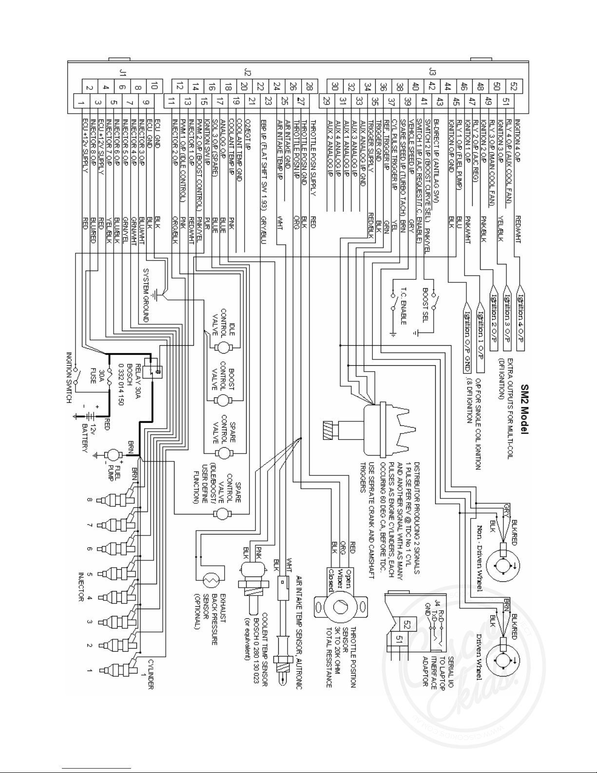
Wiring Notes.
The wiring diagrams should be followed 100%. Do not make changes that you believe will not
effect the operation of the SM2. This is one of the major causes of the engine not starting,
misfiring or SM2 diagnostic errors.
The “System Ground” (earth) shown on the wiring diagram is on the engine block or cylinder
head. Do not use the body of the car as a ground.
The injector output sequence has to be matched to your engine firing order.
Example:- Four cylinder engine with a 1,3,4,2 firing order.
Injector 1 O/P = Cylinder 1
Injector 2 O/P = Cylinder 3
Injector 3 O/P = Cylinder 4
Injector 4 O/P = Cylinder 2
The ignition output sequence if using more than one ignition coil must also be wired in the
correct sequence. See the “Ignition Output Sequence” in the hardware section of this manual.
If using a reluctor interface to convert inductive signals to hall effect type signals, then the
reluctor interface should be mounted close to the distributor or trigger sensors. The shielded
wires should directly connect to the distributor or trigger sensors, Do not use unshielded wire to
lengthen these wires.
C
I
S
C
O
K
I
D
S
P
A
R
T
S
P
R
O
J
E
C
T
W
W
W
.
C
I
S
C
O
K
I
D
S
.
C
O
M
.
A
U
Autronic SM2 Manual ver 1.6
18
Main wiring diagram
C
I
S
C
O
K
I
D
S
P
A
R
T
S
P
R
O
J
E
C
T
W
W
W
.
C
I
S
C
O
K
I
D
S
.
C
O
M
.
A
U
Autronic SM2 Manual ver 1.6
19
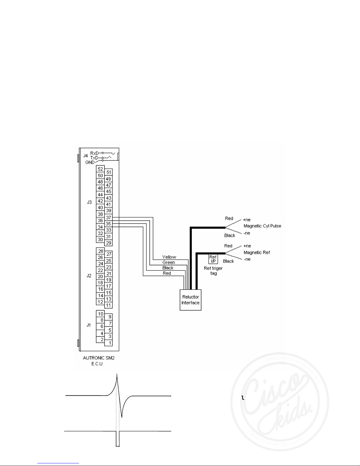
Reluctor interface (required for inductive sensors)
When using inductive sensors a reluctor interface is required. This is an option and is not
included with the ECU’s. This interface will make a square wave from the small spike generated
form the inductive sensor.
For proper function, the positive and negative wire from the sensor must be wired correctly to
the interface. If they are not marked use an oscilloscope or multi-meter to check the signal. The
+ne (red wire) connects to the wire/pin on the on the sensor that gives a positive voltage as
metal approaches the sensor.
One channel can be used if one engine sensor is inductive and the other hall-effect sensor is
wired direct to the ECU.
Input Trigger Signal
Output Trigger Signal
C
I
S
C
O
K
I
D
S
P
A
R
T
S
P
R
O
J
E
C
T
W
W
W
.
C
I
S
C
O
K
I
D
S
.
C
O
M
.
A
U
Autronic SM2 Manual ver 1.6
20
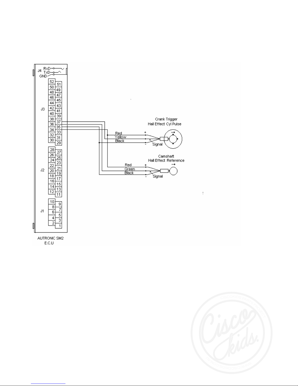
Crank Trigger wiring with hall effect sensors.
C
I
S
C
O
K
I
D
S
P
A
R
T
S
P
R
O
J
E
C
T
W
W
W
.
C
I
S
C
O
K
I
D
S
.
C
O
M
.
A
U
Table of contents
Popular Automobile Accessories manuals by other brands


Safe Fleet
Safe Fleet RVS systems RVS-M633 instruction manual

Metra Electronics
Metra Electronics AFDI-RSE-01 installation instructions

Cruz
Cruz 922-000 Assembly instructions

Driver Bubble
Driver Bubble Flex installation guide

TruXedo
TruXedo TonneauTraX owner's manual

RAWLINK
RAWLINK 20481 instruction manual