Cisco Cisco ONS 15600 SDH User manual
Other Cisco Network Hardware manuals

Cisco
Cisco NAC3350-PROF-K9 - NAC Profiler Server User manual

Cisco
Cisco 6500 - Catalyst Series 10 Gigabit EN Interface Module... User manual

Cisco
Cisco CE-507 - Content Engine 507 User manual
Cisco
Cisco Firepower 4100 Series User manual
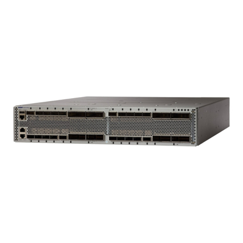
Cisco
Cisco NCS 1002 User manual

Cisco
Cisco SA-VAM - VPN Acceleration Module Operator's manual
Cisco
Cisco ATM Cable Interface Processor ACIP-SM(=) Operator's manual
Cisco
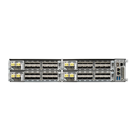
Cisco NCS 1004 User manual
Cisco
Cisco IDS-4230-FE - Intrusion Detection Sys Fast Ethernet... Operator's manual
Cisco
Cisco GS7000 Operating instructions
Cisco
Cisco ONS 15310-MA User manual
Cisco
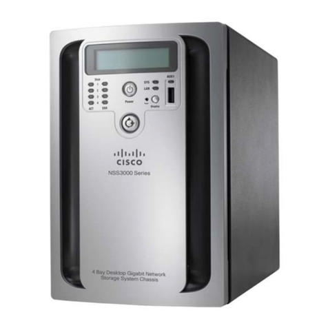
Cisco Network Storage System NSS3000 Series User manual
Cisco
Cisco Firepower 1010 Series Manual
Cisco
Cisco 2650XM User manual

Cisco
Cisco 8540 - Catalyst Campus Switch Router Modular Expansion... User manual
Cisco
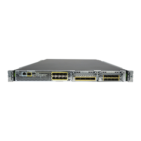
Cisco Firepower 4100 Series User manual
Cisco
Cisco MERAKI CW9166D1 User manual
Cisco
Cisco NCS 4201 Manual
Cisco
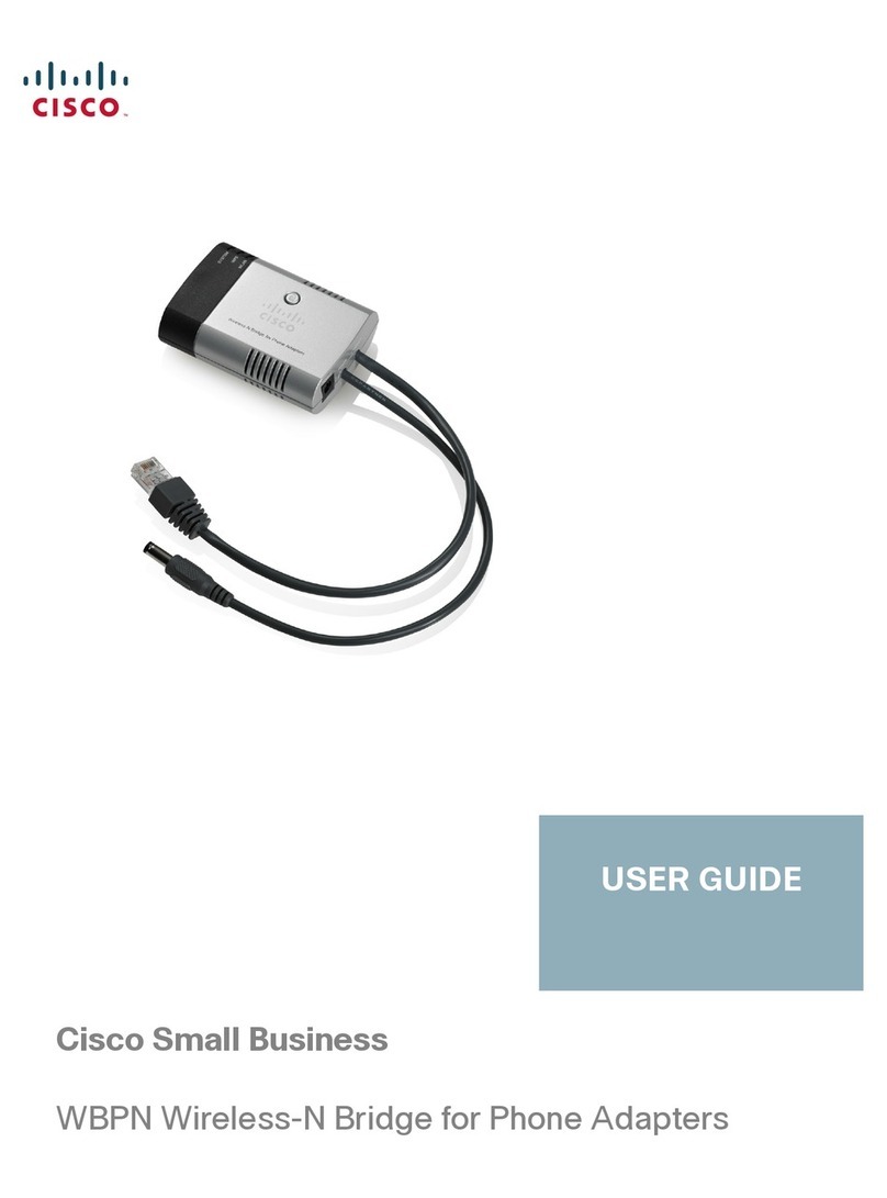
Cisco WBPN User manual

Cisco
Cisco IPS-4240-K9 - Intrusion Protection Sys 4240 User manual
Popular Network Hardware manuals by other brands

Matrix Switch Corporation
Matrix Switch Corporation MSC-HD161DEL product manual

B&B Electronics
B&B Electronics ZXT9-IO-222R2 product manual

Yudor
Yudor YDS-16 user manual

D-Link
D-Link ShareCenter DNS-320L datasheet

Samsung
Samsung ES1642dc Hardware user manual

Honeywell Home
Honeywell Home LTEM-PV Installation and setup guide
