manuals.online logo
Brands
  1. Home
  2. •
  3. Brands
  4. •
  5. Cissell
  6. •
  7. Washer
  8. •
  9. Cissell CSHW35-HW55-164 User manual

Cissell CSHW35-HW55-164 User manual

This manual suits for next models

7

Other Cissell Washer manuals

Cissell CHMW35-WE55-165 User manual

Cissell

Cissell CHMW35-WE55-165 User manual

Cissell CT055 User manual

Cissell

Cissell CT055 User manual

Cissell CHHW50-WE234 Guide

Cissell

Cissell CHHW50-WE234 Guide

Cissell CSHW50-HF145-176-234 Guide

Cissell

Cissell CSHW50-HF145-176-234 Guide

Cissell CHMW35-WE110-132-165 Guide

Cissell

Cissell CHMW35-WE110-132-165 Guide

Cissell IPSO HF234 User manual

Cissell

Cissell IPSO HF234 User manual

Cissell WE176 User manual

Cissell

Cissell WE176 User manual

Cissell CSHW35-HW131-164 Guide

Cissell

Cissell CSHW35-HW131-164 Guide

Cissell CSHW50-HF135-234 User manual

Cissell

Cissell CSHW50-HF135-234 User manual

Cissell 40-175 lb User manual

Cissell

Cissell 40-175 lb User manual

Cissell CHHW50-WE176-234 User manual

Cissell

Cissell CHHW50-WE176-234 User manual

Cissell CSHW75-HF245-304 User manual

Cissell

Cissell CSHW75-HF245-304 User manual

Popular Washer manuals by other brands

Zanussi ZWF 14080 W user manual

Zanussi

Zanussi ZWF 14080 W user manual

Zanussi FV 825 N Instruction booklet

Zanussi

Zanussi FV 825 N Instruction booklet

LG WM8000HVA Specifications

LG

LG WM8000HVA Specifications

Whirlpool 3RGSC9400 Use and care guide

Whirlpool

Whirlpool 3RGSC9400 Use and care guide

Zanussi TJ 1284 H instruction manual

Zanussi

Zanussi TJ 1284 H instruction manual

AEG KO-LAVAMAT 74740 User information

AEG

AEG KO-LAVAMAT 74740 User information

Beko WSRE7512PRA user manual

Beko

Beko WSRE7512PRA user manual

Whirlpool LA5OOOXP Use and care guide

Whirlpool

Whirlpool LA5OOOXP Use and care guide

Miele PW 6207 operating instructions

Miele

Miele PW 6207 operating instructions

GE GE Profile WWSE3160AAA Specifications

GE

GE GE Profile WWSE3160AAA Specifications

Bush WMNB712EB instruction manual

Bush

Bush WMNB712EB instruction manual

ALLIANCE UW60AV Information manual

ALLIANCE

ALLIANCE UW60AV Information manual

Bosch WAN280H3 User manual and installation instructions

Bosch

Bosch WAN280H3 User manual and installation instructions

Maytag MAT15MNAW installation instructions

Maytag

Maytag MAT15MNAW installation instructions

LG T2109VSAL owner's manual

LG

LG T2109VSAL owner's manual

Indesit IWC 61481 Instructions for use

Indesit

Indesit IWC 61481 Instructions for use

Electrolux EWF12843 user manual

Electrolux

Electrolux EWF12843 user manual

Indesit WIN 70 Instructions for use

Indesit

Indesit WIN 70 Instructions for use

manuals.online logo
manuals.online logoBrands
  • About & Mission
  • Contact us
  • Privacy Policy
  • Terms and Conditions

Copyright 2025 Manuals.Online. All Rights Reserved.

3
4
4
7
10
10
10
10
10
11
12
13
13
14
15
23
29
30
30
30
31
33
Content
Contents
1 General safety instructions ...........................................................................
2 Technical data and dimensions ....................................................................
Technical data .............................................................................................
Dimensions ..................................................................................................
3 Installation and connection ..........................................................................
Ground .........................................................................................................
Removing the transport rackets .................................................................
Water connection .........................................................................................
Water drain ..................................................................................................
Main power connection .................................................................................
Liquid soap connection ................................................................................
Connection of a central operating panel for coinmachines (option) ...............
Steam connection ........................................................................................
4 Operating instructions ..................................................................................
Machine with start utton .............................................................................
Machine with coin or token operation............................................................
5 Standard programs .......................................................................................
6 Technical remar s .........................................................................................
Internal connection of the electrical heating .................................................
Tilt switch ....................................................................................................
Error messages ...........................................................................................
7 Maintenance of the machine ........................................................................
Code: 249/00078/01
10/06/2002
3
p
p
1
General safety instructions
Ignoring any of the safety instructions can cause serious
personal injury and can also cause damage to the linen or the
machine
p
p
p
p
p
p
p
p
p
p
p
Read the installation and instruction manual carefully before connecting the
machine.
It is recommended that the machine be installed by qualified technicians.
The machine should be installed according to the installation instructions. (See
chapter 3)
The machine should be grounded according to the instructions in order to
eliminate the risk of electrocution.
Do not e pose the machine to high humidity or e treme high or low temperatures.
Cut off all main water inlets, steam and electrical supplies at the end of each
operating day.
Before starting repairs or maintenance, shut off all power and water supplies.
To prevent fire and e plosion:
Keep the area around the machine free from inflammable or combustible
products.
Do not put fabrics that are treated with inflammable products into the machine.
These fabrics should be hand-washed or air-dried first.
Always carefully read and follow the instructions on the packing of detergents.
Store these products out of the reach of children.
Always take into account the instructions on the labels of clothes.
Never allow children to play in the surroundings of a machine.
These instructions surely cannot prevent all risks of accidents. It is up to the user to act with the
utmost precaution.
Do not hesitate to contact the dealer in case of a problem.
Remark:
4
2
HW55
Technical data and dimensions
Technical data
HW55
Capacity (dry weight)
1/11 5 kg
1/10 5,5 kg
1/9 6,1 kg
Cylinder
Diameter 530 mm
Depth 250 mm
Volume 55 lit.
Cabinet
Height 1005 mm
Width 660 mm
Depth 708 mm
Front loading
Diameter door ope i g 300 mm
Door height 355 mm
To ce ter 505 mm
Speed
Wash 10 - 50 tr/mi
Distributio 85 tr/mi
Spi 500 - 1250 tr/mi
G-force
Low spi /High spi 74/462
Motor (3-phase)
4p. 1470 tr./mi 550W
rain valve
Depe d-O-Drai 6/4"
Water supply
Hot + warm water 3/4"
Heating
Electrical 230/400 V 3 kW
Electrical 400V 6 kW
Steam X
Warm water (without additio al heati g) X
Warm water (with additio al heati g) X
Packing dimensions
(H x W x D) mm 1140x732x832
Weight
Net 197 kg
Gross 252 kg
5
2
HW64/72/75/94
HW 64 HW72 HW 75 HW94
Capacity (dry weight)
1/11 5,9 kg 6,6 kg 6,9 kg 8,6 kg
1/10 6,5 kg 7,3 kg 7,6 kg 9,5 kg
1/9 7,2 kg 8,1 kg 8,4 kg 10,5 kg
Cylinder
Diameter 530 mm 530 mm 530 mm 530 mm
Depth 295 mm 345 mm 345 mm 440 mm
Volume 65 Lit. 73 Lit. 76 Lit. 95 lit.
Cabinet
Height 1005 mm 1005 mm 1005 mm 1005 mm
Width 660 mm 660 mm 660 mm 660 mm
Depth 670 mm 670 mm 670 mm 770 mm
Front loading
Diameter door ope i g 300 mm 300 mm 300 mm 300 mm
Door height 355 mm 660 mm 355 mm 355 mm
To ce ter 505 mm 505 mm 505 mm 505 mm
Speed
Wash 10 - 50 tr/mi
Distributio 85 tr/mi
Low spi 250 - 500 tr/mi
High spi 500 - 1000 tr/mi
G-force
Low spi /High spi 74/296
Motor (3-phase)
4p. 1470 tr./mi 750W
rain valve
Depe d-O-Drai 6/4"
Water supply
Hard, soft, warm water a d cool-dow 3/4"
Steam connection
Steam co ectio 3/8"
Heating
Electrical 230/400 V 4,2/6/9 kW
Electrical 400V 12 kW
Steam X
Warm water (without additio al heati g) X
Warm water (with additio al heati g) X
Packing dimensions
(H x W x D) mm 1140x732x832 1240x732x950
Weight
Net 197 kg 210 kg 210 kg 212 kg
Gross 252 kg 265 kg 265 kg 268 kg
6
2
HW131/164
HW 131 HW 164
Capacity (dry weight)
1/11 12 kg 15 kg
1/10 13,2 kg 16,5 kg
1/9 14,5 kg 18,3 kg
Cylinder
Diameter 650 mm 650 mm
Depth 400 mm 400 mm
Volume 132 Lit. 165 Lit.
Cabinet
Height 1170 mm 1170 mm
Width 780 mm 780 mm
Depth 760 mm 860 mm
Front loading
Diameter door ope i g 300 mm 300 mm
Door height 455 mm 455 mm
To ce ter 605 mm 605 mm
Speed
Wash 50 tr/mi
Distributio 100 tr/mi
Low spi 250--500 tr/mi
High spi 500--1000 tr/mi
G-force
Low spi /High spi 88/363
Motor (3-phase)
4p. 1470 tr./mi 1500W
rain valve
Depe d-O-Drai 6/4"
Water supply
Hard, soft, warm water a d cool-dow 3/4"
Steam connection
Steam co ectio 3/8"
Heating
Electrical 230/400 V 12/15/18 kW
Electrical 400V 21/24 kW
Steam X
Warm water (without additio al heati g) X
Warm water (with additio al heati g) X
Packing dimensions
(H x W x D) 1310x850x1000mm 1310x850x1100mm
Weight
Net 287 kg 347 kg
Gross 349 kg 417 kg
7
2
HW
2
A. Hard water connection 3/4"
B. Warm water connection 3/4"
C. Input electrical supply
D. Electrical connection clamps
E. Ventilation soap dispenser
F. Water drain
G. Bolt pattern for fi ation of the machine
Dimensions
8
p
p
p
p
p
p
p
p
p
2
HW64/72/7 /94
A. Hard water connection 3/4"
B. Warm water connection 3/4"
C. Soft water connection 3/4"
D. Output connection steam valve
E. Input electrical supply
F. Electrical connection clamps
G. Water drain
H. Steam connection
I. Ventilation soap dispenser
9
2
p
p
p
p
p
p
p
p
p
HW131/164
A. Hard water connection 3/4"
B. Warm water connection 3/4"
C. Soft water connection 3/4"
D. Output connection steam valve
E. Input electrical supply
F. Electrical connection clamps
G. Water drain
H. Steam connection
I. Ventilation soap dispenser
10
3
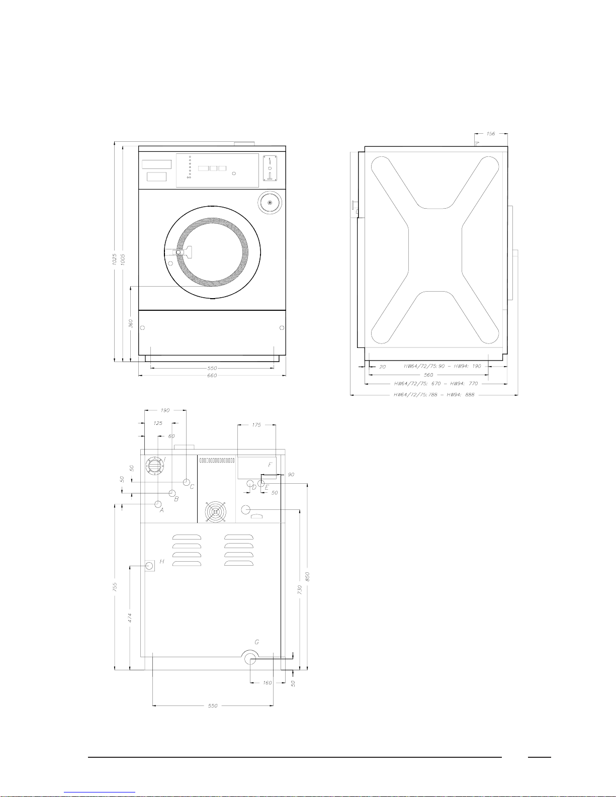
The machine must be placed on a flat, solid surface (metal base, concrete or solid
ground). It is recommended that the machine be anchored (bolts M10) on the
provided places (A) in the base, especially in case of a plint (see Dimensions 2).
The machine must be placed entirely level. For easy maintenance it is recommen-
ded to keep a minimal distance of 600 mm between the wall and the back of the
machine.
If several machines are placed ne t to each another, there should be a minimal
distance of 30 mm between each machine.
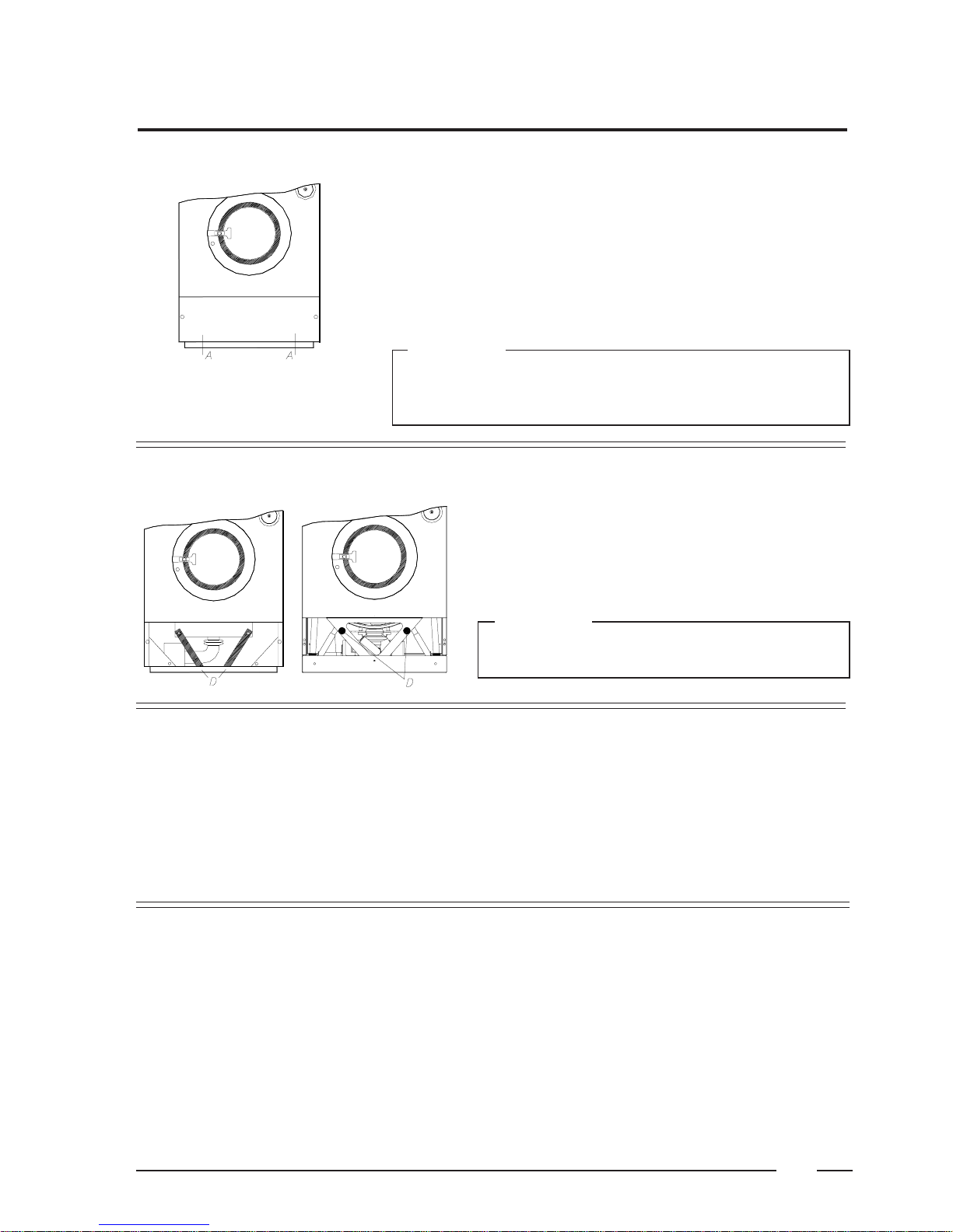
To prevent damage during transportation, the machine has been
equipped with two red transport brackets (D) to eliminate every
possible movement of the tub.
After the machine has been placed level, take off the service panel
and remove these transport brackets.
Important
The machine must never be activated before removing
these transport brackets.
Removing the transport brackets
The machine is delivered with hoses with 3/4" connections. These hoses fit the
water inlet valves of the machine and the main water inlet taps. To ensure the
optimal functioning of the water inlet valves, the water pressure on the inlet
should be between 0,5 and 10 kg/cm² (7 and 145 psi). If the pressure is too low,
the cycle time will increase considerably.
In case of boiler fed machines, a minimum of hot water of 90°C should
be available: HW55: 46l. HW64: 55 l. HW75: 65 l. HW94: 80l.
HW131: 100l. HW164: 120l.
Water connection
Water drain The machine is equipped with a drain valve with 6/4" outer diameter (50 mm). This
drain valve should be connected to the drain by means of the drain elbow which
is delivered with the machine.
The diameter of the main drain should be adapted to the water flow and the
number of machines. It should be sufficient to handle at least 80L/min. per
machine.
It is necessary to connect the main drain at least on one side to an open air-
brake to allow ventilation.
p
p
Installation and connection
round
Important
The bolt pattern for the fi ation of the HW 55 machine is foreseen in the back
panel of the cabinet. Put this panel on the floor and indicate the holes (see page
7).