CityGrow Systems CG400 Series User manual

CG400 SERIES
ZIGBEE WIRELESS MODULE
USER MANUAL
CG400SW
One-Gang Switch Module
CG400FL
0-10V Dimming Module
CG400DM
One-Gang Dimmer Module
CG400S2-CCP
One-Gang Curtain Control Switch
Module
VERSION 1.5
11 MARCH,2020
Disclaimers and Copyright
Nothing contained in this publication is to be construed as granting any right, by implication or otherwise, for the manufacture,
sale, or use in connection with any method, apparatus, or product covered by letters patent, or as insuring anyone against liability
for infringement of letters patent.
Efforts have been made to ensure the accuracy and reliability of the data contained in this publication; however, CityGrow Energy
Systems Limited makes no representation, warranty, or guarantee in connection with this publication and hereby expressly
disclaims any liability or responsibility for loss or damage resulting from its use or from the use of any product or methodology
described herein; for any violation of any federal, state, or municipal regulation with which this publication may conflict; or for
the infringement of any patent from the use of this publication. Nothing contained in this publication should be viewed as an
endorsement by CityGrow Energy Systems Limited of any particular manufacturer’s products.

i
CAUTION
RISK OF ELECTRIC SHOCK DO NOT OPEN
CAUTION: TO REDUCE THE RISK OF ELECTRIC SHOCK,
DO NOT REMOVE COVER (OR BACK) NO USER-SERVICEABLE
PARTS INSIDE REFER SERVICING TO QUALIFIED SERVICE PERSONNEL
The lightning flash with arrowhead symbol within an equilateral triangle is intended to alert the user to
the presence of uninsulated “dangerous voltage” within the product’s enclosure that may be of sufficient
magnitude to constitute a risk of electric shock to persons.
The exclamation point within an equilateral triangle is intended to alert the user to the presence of
important operating and maintenance (servicing) instructions in the literature accompanying the product.
IMPORTANT SAFETY INSTRUCTIONS
READ BEFORE OPERATING EQUIPMENT
This product was designed and manufactured to meet strict quality and safety standards.
There are, however, some installation and operation precautions which you should be particularly aware of.
1. Read these instructions.
2. Keep these instructions.
3. Heed all warnings.
4. Follow all instructions.
5. Do not use this apparatus near water.
6. Clean only with dry cloth.
7. Do not block any ventilation openings. Install in accordance with the manufacturer’s instructions.
8. Do not install near any heat sources such as radiators, heat registers, stoves, or other apparatus that produce heat.
9. Do not defeat the safety purpose of the polarized or grounding-type plug. If the provided plug does not fit into your outlet,
consult an electrician for replacement of the outlet.
10. Protect the power cord from being walked on orpinched particularly at plugs, convenience receptacles, and the point where
they exit from the apparatus.
11. Only use attachments/accessories specified by the manufacturer.
12. Use only with the cart, stand, tripod, bracket, or table specified by the manufacturer, or sold with the apparatus. When a
cart is used, use caution when moving the cart/apparatus combination to avoid injury from tip-over.
13. Unplug this apparatus during lightning storms.
14. Refer all servicing to qualified service personnel. Servicing is required when the apparatus has been damaged in any way,
such as power-supply cord or plug is damaged, liquid has been spilled or objects have fallen into the apparatus, the
apparatus has been exposed to rain or moisture, does not operate normally, or has been dropped.

ii
Table of content
1. Introduction................................................................................................ 1
2. Understanding the product ........................................................................... 2
2.1. CG400SW .......................................................................................... 2
2.2. CG400DM .......................................................................................... 4
2.3. CG400FL............................................................................................ 6
2.4. CG400S2-CCP .................................................................................... 8
3. Dimensions ............................................................................................... 10
3.1. CG400SW ........................................................................................ 10
3.2. CG400DM ........................................................................................ 10
3.3. CG400FL.......................................................................................... 11
3.4. CG400FL.......................................................................................... 11
4. Wiring ...................................................................................................... 12
4.1. CG400SW / CG400DM....................................................................... 13
4.2. CG400FL.......................................................................................... 14
4.3. CG400S2-CCP .................................................................................. 15
5. Installation................................................................................................ 16
6. Programming the travelling time of the motorized curtain ............................. 19
7. Application notes....................................................................................... 20
8. Adding the product to your Home Wireless ZigBee Network .......................... 21
9. Specification.............................................................................................. 22

1
1. Introduction
Thank you for choosing CityGrow’s product. CG400 Series is highly-functional, user-friendly
and installation-friendly. These products are specially designed for Home Automation and
lighting control purpose. The durability of the CG400 Series is very high, it can operate for more than
100,000 times of on / off control. Zero-crossing control technique has been applied to the CG400 Series
which enabled the modules’capability in handling high capacitive loads, especially LED lighting fixtures.
A powerful unique feature - default ON / OFF / Last Status after power-up options of the CG400 Series
products, makes the modules are applicable to most different situations and fulfill various operation
requirements.
Description
1. ZigBee / IEEE 802.15.4 2.4GHz wireless remote control.
2. Zero-crossing control technique for high capacitive loads.
3. Default ON / OFF / Last Status after power-up options.
4. LED indicator for operation indication.
5. Equipped with control button and reset button for test and commissioning.
6. Compact size and easy to install in suspended ceiling.
7. Direct AC 220V input.
8. CG400SW –On/Off control.
9. CG400FL –1-10V dimming control.
10. CG400DM –leading edge dimming control.
11. CG400S2-CCP –Open/Close control for electric or motorized curtain and window
blind.
12. All the modules can be remotely controlled by CityGrow’s ZigBee devices / panels.
13. With CG102BS-R Base Station, all devices support iOS/Android App control.
Certifications
EN 50371 (EN 62479), EN 60669-2-1, EN 60669-1+A1, EN 301 489-1, EN 301 489-3,
EN 300 440-1, EN 300 440-2, E134517, VDE 40027342

2
2. Understanding the product
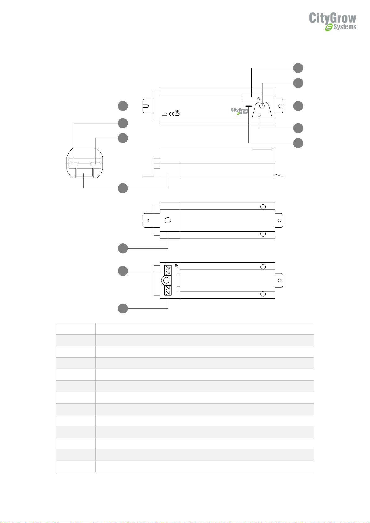
2.1. CG400SW
RESET
Model: CG400SW
ONE GANG SWITCH MODULE
AC120-240V, 50Hz/60Hz
MAX. LOAD: 6.3A (RESISTIVE)
EN 60669-2-1
IEEE802.15.4, 2.4GHz
MADE IN CHINA
RoHS SW
2
1
3
4
5
7
6
8
9
10
11
12
LABEL
Description
1
Mounting hole
2
AC input wire clip
3
Output wire clip
4
AC input / output wire cover
5
AC input / output wire cover
6
Output wire terminal (Open the AC input / output wire cover)
7
AC input wire terminal (Open the AC input / output wire cover)
8
Programming port cover
9
ON / OFF control test button
10
Mounting hole
11
Reset button
12
Operation LED indicator

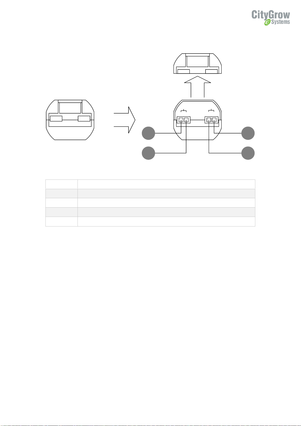
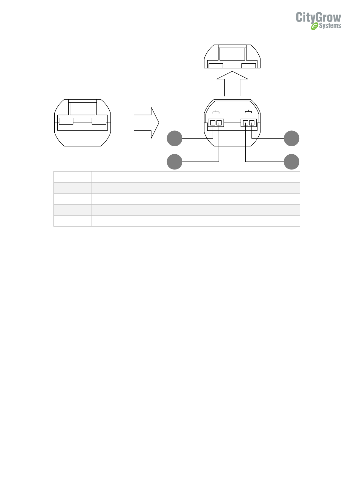
3
L N
OUTPUT
N L
INPUT
1
2
3
4
Open the AC input / output wire cover
LABEL
Description
1
Output Live terminal
2
Output Neutral terminal
3
Input Live terminal
4
Input Neutral terminal
4
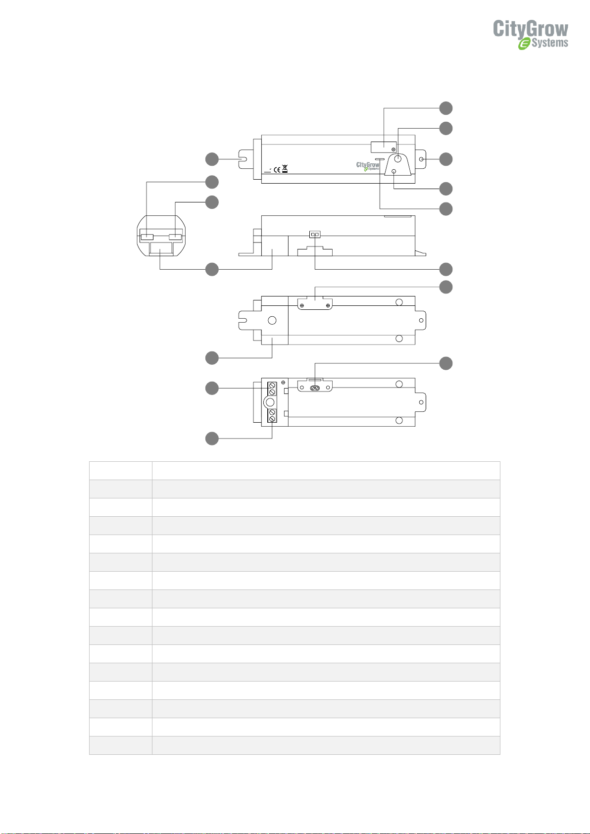
2.2. CG400DM
RESET
Model: CG400DM
DIMMER MODULE
AC120-240V, 50Hz/60Hz
MAX. LOAD: 400VA
EN 60669-2-1
IEEE802.15.4, 2.4GHz
MADE IN CHINA
RoHS DM
2
1
3
4
5
7
6
8
9
10
11
12
LABEL
Description
1
Mounting hole
2
AC input wire clip
3
Output wire clip
4
AC input / output wire cover
5
AC input / output wire cover
6
Output wire terminal (Open the AC input / output wire cover)
7
AC input wire terminal (Open the AC input / output wire cover)
8
Programming port cover
9
ON / OFF control test button
10
Mounting hole
11
Reset button
12
Operation LED indicator
5
L N
OUTPUT
N L
INPUT
1
2
3
4
Open the AC input / output wire cover
LABEL
Description
1
Output Live terminal
2
Output Neutral terminal
3
Input Live terminal
4
Input Neutral terminal
6
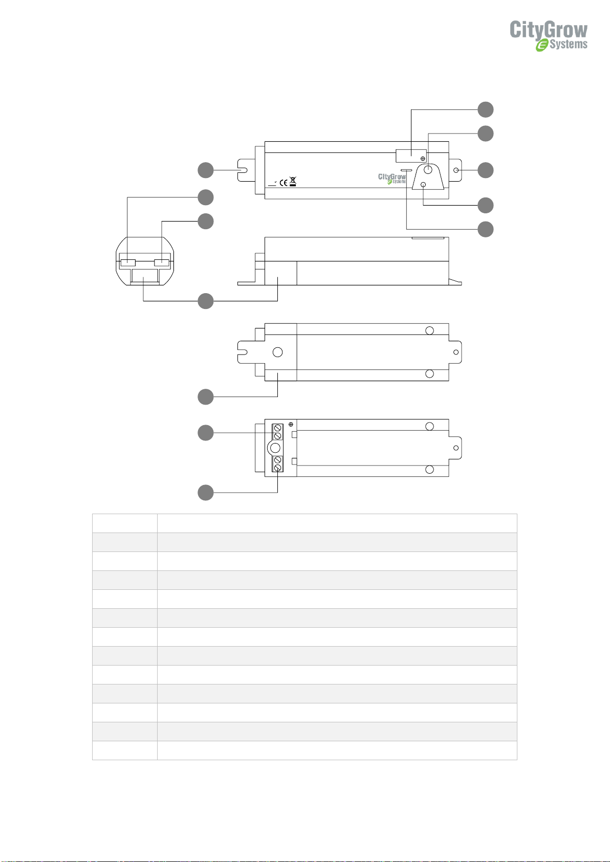
2.3. CG400FL
RESET
Model: CG400FL
ONE GANG SWITCH MODULE
AC120-240V, 50Hz/60Hz
MAX. LOAD: 6.3A (RESISTIVE)
EN 60669-2-1
IEEE802.15.4, 2.4GHz
MADE IN CHINA
RoHS FL
- 0-10VDC +
25mA OUTPUT
2
1
3
4
5
7
6
8
9
10
11
12
13
15
14
LABEL
Description
1
Mounting hole
2
AC input wire clip
3
Output wire clip
4
AC input / output wire cover
5
AC input / output wire cover
6
Output wire terminal (Open the AC input / output wire cover)
7
AC input wire terminal (Open the AC input / output wire cover)
8
Programming port cover
9
ON / OFF control test button
10
Mounting hole
11
Reset button
12
Operation LED indicator
13
1-10V Dimming signal output terminal
14
1-10V Dimming signal output terminal screw cover
15
1-10V Dimming signal output terminal screw

7
L N
OUTPUT
N L
INPUT
1
2
3
4
Open the AC input / output wire cover
LABEL
Description
1
Output Live terminal
2
Output Neutral terminal
3
Input Live terminal
4
Input Neutral terminal
8
2.4. CG400S2-CCP
RESET
Model: CG400S2-CCP
3 WIRES CURTAIN CONTROL UNIT
AC120-240V, 50Hz/60Hz
MAX. LOAD: 2AX 2
EN 60669-2-1
IEEE802.15.4, 2.4GHz
MADE IN CHINA
RoHS CCP
2
1
3
4
5
7
6
8
9
10
11
12
LABEL
Description
1
Mounting hole
2
AC input wire clip
3
Output wire clip
4
AC input / output wire cover
5
AC input / output wire cover
6
Output wire terminal (Open the AC input / output wire cover)
7
AC input wire terminal (Open the AC input / output wire cover)
8
Programming port cover
9
ON / OFF control test button
10
Mounting hole
11
Reset button
12
Operation LED indicator
9
L1 L2
OUTPUT
N L
INPUT
1
2
3
4
LABEL
Description
1
Output curtain open control terminal
2
Output curtain close control terminal
3
Input Live terminal
4
Input Neutral terminal
10
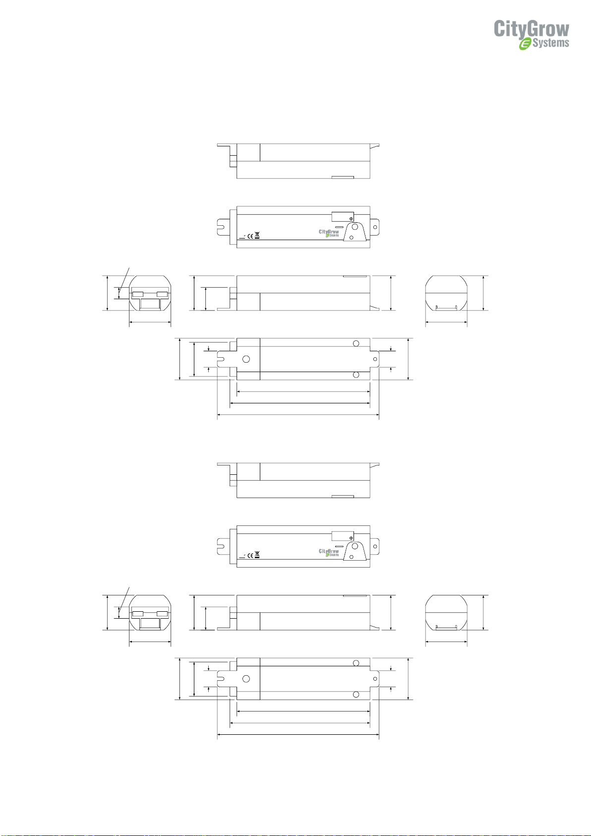
3. Dimensions
3.1. CG400SW
36mm
140mm
121mm
115mm
14mm
14mm
30mm
36mm
30mm
30mm
20mm
30mm
36mm36mm
10mm
30mm
RESET
Model: CG400SW
ONE GANG S WITCH MODULE
AC120-240V, 50Hz/60Hz
MAX. LOAD: 6.3A (RESISTIVE)
EN 60669-2-1
IEEE802.15.4, 2.4GHz
MAD E IN C HIN A
RoHS SW
3.2. CG400DM
36mm
140mm
121mm
115mm
14mm
14mm
30mm
36mm
30mm
30mm
20mm
30mm
36mm36mm
10mm
30mm
RESET
Model: CG400DM
DIMMER MODULE
AC120-240V, 50Hz/60Hz
MAX. LOAD: 400VA
EN 60669-2-1
IEEE802.15.4, 2.4GHz
MAD E IN C HIN A
RoHS DM
11
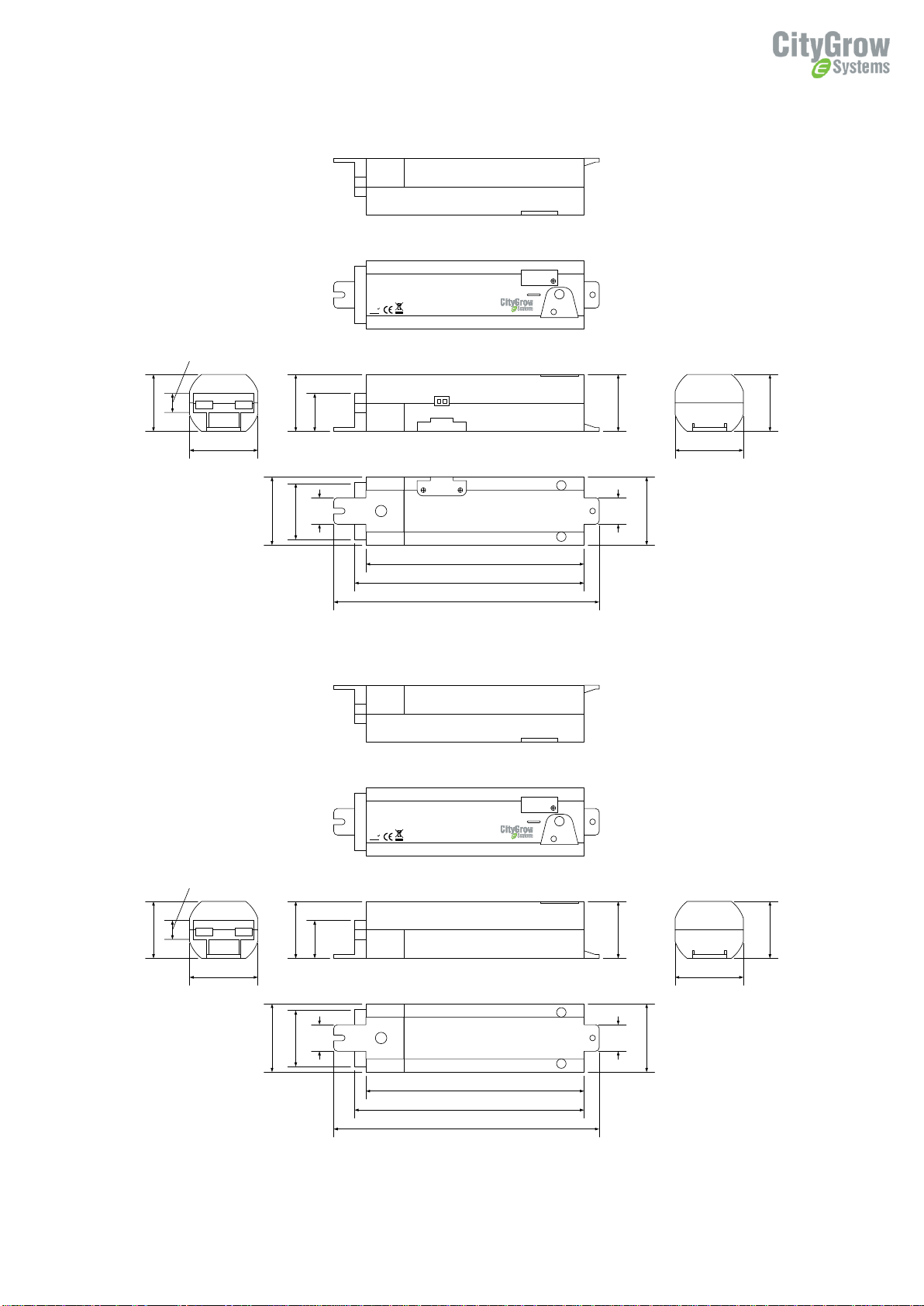
3.3. CG400FL
36mm
140mm
121mm
115mm
14mm
14mm
30mm
36mm
30mm
30mm
20mm
30mm
36mm36mm
10mm
30mm
- 0-10VDC +
25mA OUTPUT
RESET
Model: CG400FL
ONE GANG SWITCH MODULE
AC120-240V, 50Hz/60Hz
MAX. LOAD: 6.3A (RESISTIVE)
EN 60669-2-1
IEEE802.15.4, 2.4GHz
MADE IN CHIN A
RoHS FL
3.4. CG400FL
36mm
140mm
121mm
115mm
14mm
14mm
30mm
36mm
30mm
30mm
20mm
30mm
36mm36mm
10mm
30mm
RESET
Model: CG400S2-CCP
3 WIRES CURTAIN CONTROL UNIT
AC120-240V, 50Hz/60Hz
MAX. LOAD: 2AX 2
EN 60669-2-1
IEEE802.15.4, 2.4GHz
MADE IN CHIN A
RoHS CCP

12
4. Wiring
Before getting started
WARNING! It must be installed by a qualified electrician in accordance with all
applicable regulations and building codes. Improper wiring can result in personal
injury or damage to control units or other equipment. Always turn off circuit breaker
or remove main fuse from power line before doing any work. To avoid overheating
and possible damage to equipment.
WARNING! Do not operate when any lamps removed or burned out; replace any
burned out lamps immediately; use only transformers that incorporate thermal
protection or fused primary windings. ! This product is designed for residential and
commercial use, for indoor use only.
WARNING! Install in accordance to all national and local electrical codes.
IMPORTANT! CityGrow® is not liable for any damage incurred with the misuse of the
product.
IMPORTANT! Pre-setup can only be done by a professional technician or
manufacturer agent.
13
4.1. CG400SW / CG400DM
Distribution Panel
Live
Neutral Neutral
Load
Load
L N
OUTPUT
NL
INPUT

14
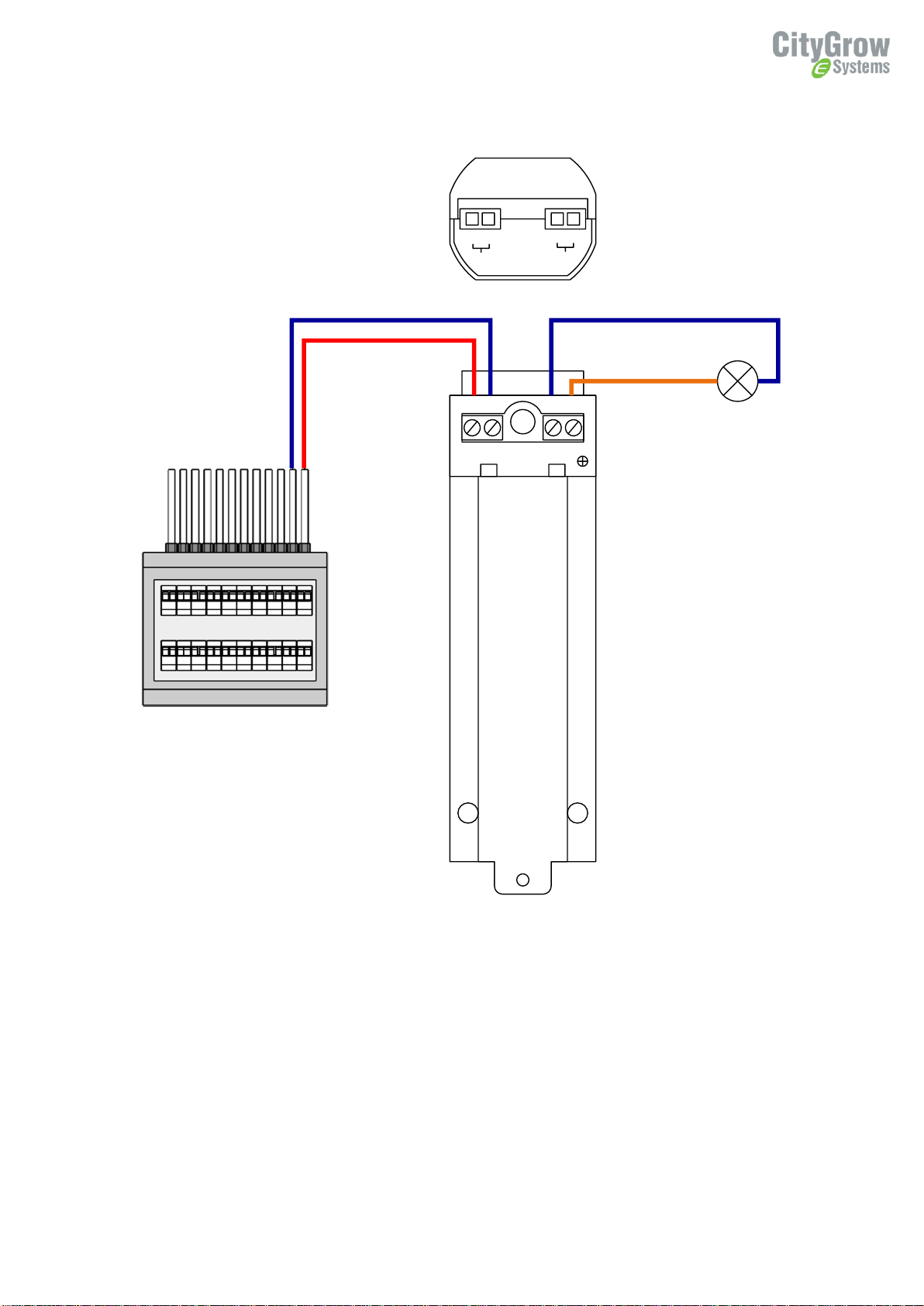
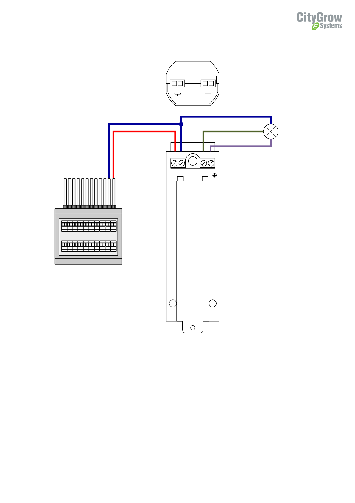
4.2. CG400FL
Distribution Panel
Live
Neutral Neutral
Load
Load
L N
OUTPUT
NL
INPUT
Driver
DC -
DC +
15
4.3. CG400S2-CCP
Distribution Panel
Live
Neutral Neutral
L1
Load
L1 L2
OUTPUT
NL
INPUT
L2
16
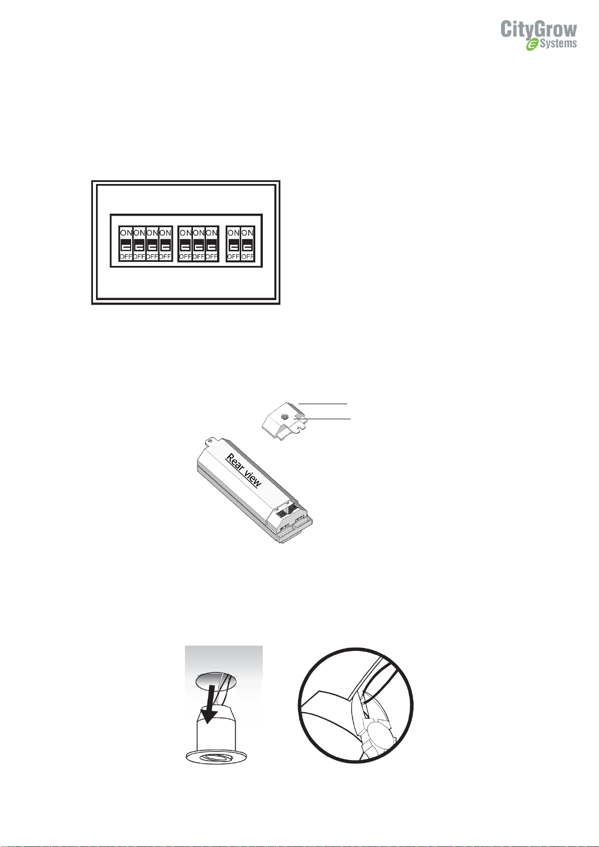
5. Installation
Please follow the instructions to install the product.
STEP 1: IMPORTANT! Turn off main power at the main switch board.
STEP 2: Loosen the wire cover screw and remove the wire cover.
STEP 3: Remove the light fixture from the ceiling and cut the original wiring going to the
light, approximately 10 to 15 cm from the light fixture. (Load and Neutral).
Wire cover screw
Wire cover

17
STEP 4: Connect the main power cable to the Live and Neutral terminals. Connect the load
cable to the Load terminals at the back cabinet of the product.
L N
OUTPUT
N L
INPUT
Live from MCB
Neutral from MCBNeutral to Load
Output to Load
*** For CG400FL, connect 1-10V DC dimming voltage output to the corresponding
input of the lamp/ lamp driver. See following diagram
- 0-10VDC +
25mA OUTPUT
This manual suits for next models
4
Table of contents
Popular Control Unit manuals by other brands


CRE Technology
CRE Technology i4GEN Technical documentation

UNICORECOMM
UNICORECOMM UM220-IV M0 Installation and Operation User Manual

LRX
LRX LRX2102 quick start guide

NuTone
NuTone 329H instructions

Honeywell
Honeywell JADE W7220 Installation instructions and operators manual

Telit Wireless Solutions
Telit Wireless Solutions SE867-AGPS user guide


