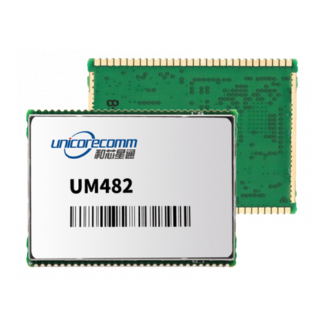
UNICORECOMM UM482 User manual

I
UM482
GPS/BDS/GLONASS/Galileo
All-constellation Multi-frequency
High Precision RTK and Heading
Module

Revision History
Version
Revision History
Date
Ver. 1.0
First release
Aug. 2017
R3.1
Revise the description of RST_N
configuration and the action execution
time
Add the related description to clarify the VCC
restrictions
2019-08-26
R3.2
Chapter 2.1: delete the legacy
parameter and add pin mechanical spec
Chapter 2.2: add the working current
info of No.17 pin
2019-10-14
Disclaimer
Information in this document is subject to change without notice and does not
represent a commitment on the part of Unicore Communications, Inc. No part of this
manual may be reproduced or transmitted in any form or by any means, electronic or
mechanical, including photocopying and recording, for any purpose without the express
written permission of a duly authorized representative of Unicore Communications, Inc.
The information contained within this manual is believed to be true and correct at the
time of publication. © Copyright 2009-2019 Unicore Communications, Inc. All rights
RSV.

III
Foreword
This <User Manual> offers you information in the features of the hardware, the
installation, specification and use of Unicore UM482 product.
For the generic version of this manual, please refer to different part of the manual according to your
purchased product configuration, concerning CORS, RTK and Heading.
Readers it applies to
This <User Manual> is applied to the technicists who know GNSS Receiver to some
extent but not to the general readers.

I
Contents
1OVERVIEW ............................................... 1
1.1 KEY FEATURES ................................................................................................................................... 1
1.2 TECHNICAL SPECIFICATIONS.................................................................................................................. 2
1.3 INTERFACES....................................................................................................................................... 3
2HARDWARE ............................................... 4
2.1 DIMENSIONS..................................................................................................................................... 4
2.2 PIN DEFINITION AND INS COORDINATE SYSTEM (TOP VIEW)................................................................... 5
2.3 PIN FUNCTION................................................................................................................................... 6
2.4 ELECTRICAL SPECIFICATIONS ................................................................................................................. 9
2.5 OPERATION CONDITION .................................................................................................................... 10
2.6 PHYSICAL SPECIFICATIONS.................................................................................................................. 11
3HARDWARE DESIGN ....................................... 11
3.1 DESIGN IN CONSIDERATIONS .............................................................................................................. 11
3.2 UM482 REFERENCE DESIGN ............................................................................................................. 12
3.3 PINS.............................................................................................................................................. 13
3.4 PCB PACKAGING ............................................................................................................................. 15
3.5 RESET SIGNAL.................................................................................................................................. 15
4INSTALLATION AND CONFIGURATION ......................... 16
4.1 ESD HANDLING PRECAUTIONS ............................................................................................................ 16
4.2 HARDWARE INSTALLATION ................................................................................................................. 16
4.3 POWER ON..................................................................................................................................... 19
4.4 CONFIGURATION AND OUTPUT ........................................................................................................... 19
4.5 OPERATION STEPS............................................................................................................................ 20
5CONFIGURATION COMMANDS................................. 21
5.1 REFERENCE STATION CONFIGURATION .................................................................................................. 23
5.2 MOVING BASE CONFIGURATIONS........................................................................................................ 24
5.3 RTK ROVER CONFIGURATION ............................................................................................................. 24
5.4 HEADING CONFIGURATION................................................................................................................. 25
5.5 HEADING2 CONFIGURATION............................................................................................................... 25
5.6 INERTIAL NAVIGATION....................................................................................................................... 26
6ANTENNA DETECTION ..................................... 27
7FIRMWARE UPGRADE ...................................... 27
8SOLDERING RECOMMENDATION............................... 29
9PACKAGING ............................................. 30

1
1Overview
UM482 is the smallest all-constellation multi-frequency high precision RTK and heading
module, developed by Unicore Communications, Inc. The module is targeting Roberts,
UAVs and intelligent drive applications.
The UM482 can provide reliable centimeter-level accuracy and high accuracy heading
output at high update rate.
By employing a single UC4C0(432 channel tracking) baseband chip and a single RF chip,
using single-sided SMD packaging, UM482 can achieve very small size (30x40mm). It
can simultaneously track GPS L1/L2 + BDS B1/B2 (B3)+ GLONASS L1/L2+Galileo
E1/E5b+QZSS.
The UM482 adopts Unicore’s new-generation “UGypsophila” RTK processing technology
and takes advantage of the high-performance data sharing capability and super-
simplified operating system within the Nebulas-II GNSS SoC chip. It performs sufficient
optimization on the multi-dimensional RTK matrix pipeline computation, resulting in
much higher RTK processing capability. With on-board MEMS chip and U-Fusion
integrated navigation algorithm, UM482 can maintain excellent application experience
even in the most challenging environments such as urban canyons, tunnels and
obstructions.
Figure 1-1 UM482 Module
1.1 Key Features
30×40mm, smallest footprint multi-frequency RTK and heading module, SMD
package
Support GPS L1/L2+BDS B1/B2 (B3) +GLONASS L1/ L2+GALILEO E1/E5b
Precise RTK positioning and heading
Instant RTK Initialization time < 5s
Dual antenna input with support of antenna signal detection

UM482 User Manual
20Hz data output rate
Adaptive recognition of RTCM input data format
On board MEMS integrated navigation
Support odometer input and external high-performance IMU interface*
1.2 Technical Specifications
Table 1-1 Performance Specifications
Channels
432 channels, based on
Nebulas-II SoC chip
Time to First Fix
(TTFF)
<25s
Frequency
GPS L1/L2
BDS B1/B2 (B3)
GLONASS L1/L2
Galileo E1/E5b
Initialization time
<5s(typical)
Single point
positioning(RMS)
Horizontal:1.5m
Vertical:3.0m
Initialization
reliability
>99.9%
DGPS(RMS)
Horizontal:0.4m
Differential data
RTCM 2.3/3.0/3.2
Vertical:0.8m
Data formats
NMEA-0183,
Unicore Binary*
RTK(RMS)
Horizontal:1cm+1ppm
Update Rate
20Hz
Vertical:1.5cm+1ppm
Time accuracy
(RMS)
20ns
Heading Accuracy
(RMS)
0.2 degree/1m baseline
Data
accuracy(RMS)
0.03m/s
INS
< 5% * driving distance (without
satellites within 30s)
Power
Consumption
2.4W(Typical)
Size
30×40×4 mm
Weight
8g

3
Table 1-2 Functional Ports
3x UART, 1xI2C, 1x SPI (LV-TTL)
1x1PPS(LV-TTL)
1x Event input
Note: * represents optional configuration
1.3 Interfaces
RF In
RF
Chip
SAW
Filter
Nebulas-II
MEMS Chip
UART
SPI
GPS
BDS
GLO
GAL
QZSS
SBAS
Interface Event
TCXO
RF In SAW
Filter
I2C
ANT1_PWR
ANT2_PWR
PPS
Figure 1-2 Block Diagram
RF Part
The receiver gets filtered and enhanced GNSS signal from the antenna via a coaxial
cable. The RF part convert the RF input signals into the IF signal, and convert IF
analog signal into digital signals required for Nebulas II chip (UC4C0).
Nebulas-II SoC( UC4C0)
Nebulas-II (UC4C0) is Unicore’s new generation high precision GNSS SoC with 55nm
low power design, supports up to 12 digital intermediate frequency or 8 analog

UM482 User Manual
intermediate frequency signals, which can track 12 navigation signals with 432
channels.
MEMS
By deploying anti-interference function block and on-board MEMS device, UM482
maintains excellent application experience in the challenging environments such as
urban canyons.
1PPS
UM482 outputs 1 Pulse-per-second time strobe with corresponding time and
positioning tag. The pulse width/polarity is configurable.
Event
UM482 provides 1 Event Mark Input with adjustable pulse width and polarity.
Reset(RST_N)/Factory Default(FRESET_N)
The reset signal RST_N is active low, no less than 20ms effective time.
When the FRESETN_N is effective, the user parameter in NVM will be cleared and
the module is restored to factory default settings. The FRESET_N is active low.
Please pull FRESET_N pin to low level for more than 5s to ensure successful reset.
2Hardware
2.1 Dimensions
Table 2-1 Dimensions
Symbol
Value(mm)
Tolerance (mm)
A
40.00
-0.2 +0.5
B
30.00
±0.2
C
4.00
±0.2
D
1.58
±0.1
E
1.27
±0.1
K
0.91
±0.1
M
1.35
±0.1
N
0.66
±0.1

5
Figure 2-1 UM482 Mechanical Diagram
2.2 Pin Definition and INS Coordinate System (Top View)
The UM482 has 2x30 pins depicted as below. The X, Y axis indicates the INS
coordinate of the module.

UM482 User Manual
Figure 2-2 UM482 Pin Diagram
2.3 Pin Function
Table 2-2 Pin Descriptions
No.
Pin
I/O
Description
1
GND
-
Ground
2
ANT1_IN
I
GNSS antenna signal input (primary
antenna)
X
Y

7
No.
Pin
I/O
Description
3
GND
-
Ground
4
GND
-
Ground
5
ANT1_IN
I
GNSS antenna power supply (heading
antenna)
6
GND
-
Ground
7
ANT_NLOD
O
Primary GNSS antenna open circuit
indicator
1: normal
0: antenna is open circuit
8
ANT_FFLG
O
Primary GNSS antenna short circuit
indicator
1: normal
0: antenna is short circuit
9
GND
-
Ground
10
RSV
-
RSV
11
RSV
-
RSV
12
RSV
-
RSV
13
RSV
-
RSV
14
GND
-
Ground
15
SPEED
I
odometer- pulse (reserved)
16
FWR
I
odometer- direction (reserved)
17
V_BACKUP
I
When the main power supply of the
module VCC is cut off, V_BCKP
supplies power to RTC and SRAM.
Level requirements: 2.0~ 3.6 V, and
the working current is about 10uA.
Can be suspended without using
the hot start function
18
GND
-
Ground
19
PVT STAT
O
PVT positioning indicator, active-high.
The module outputs high level when
positioning and outputs low level
when no positioning is proceeded.
20
GPIO2
I/O
General IO
21
RSV
-
RSV
22
FRESET_N
I
Reset to factory default (clear all user
settings), LVTTL active-low, press

UM482 User Manual
No.
Pin
I/O
Description
longer than 5 seconds
23
ERR_STAT
O
Abnormal indicator, active-high.
When the self-diagnosis of the
module system fails, it outputs high
level, alternatively outputs low level
when the module completes the self-
diagnosis.
24
RTK_STAT
O
RTK positioning indicator, active-high.
When the RTK solution is fixed, it
outputs high level, alternatively
outputs low level when it’s in other
positioning states or no positioning is
proceeded.
25
GND
-
Ground
26
SPI_MISO
I
SPI data master input slave output
27
SPI_MOSI
O
SPI data master output slave input
28
SPI_CLK
O
SPI clock
29
SPI_SS0
O
SPI chip select 0
30
SPI_SS1
O
SPI chip select 1
31
3.3V_VCC
Power
Power Supply (+3.3V)
32
3.3V_VCC
Power
Power Supply (+3.3V)
33
GND
-
Ground
34
GND
-
Ground
35
TXD1
I/O
COM 1 transmit
36
RXD1
I
COM 1 receive
37
TXD2
O
COM 2 transmit
38
RXD2
I
COM 2 receive
39
TXD3
O
COM 3 transmit
40
RXD3
I
COM 3 receive
41
I2C_SDA
I/O
I2C data
42
I2C_SCL
I/O
I2C clock
43
GND
-
Ground
44
PPS
O
Pulse per second
45
EVENT
I
Event Mark
46
RST_N
I
Fast reset, will not clear user
configurations. active Low
47
GND
-
Ground

9
No.
Pin
I/O
Description
48
RSV
-
RSV
49
RSV
-
RSV
50
RSV
-
RSV
51
RSV
-
RSV
52
GND
-
Ground
53
ANT2_FFLG
O
Secondary GNSS antenna short circuit
indicator
1: normal
0: antenna is short circuit
54
ANT2_NLOD
O
Secondary GNSS antenna open circuit
indicator
1: normal
0: antenna is open circuit
55
GND
-
Ground
56
ANT2_PWR
I
Secondary GNSS antenna power
supply
57
GND
-
Ground
58
GND
-
Ground
59
ANT2_IN
I
Secondary GNSS antenna signal
(Heading antenna)
60
GND
-
Ground
2.4 Electrical Specifications
Table 2-3 Absolute Maximum Ratings
Item
Pin
Min
Max
Unit
Power Supply (VCC)
Vcc
-0.3
3.6
V
Voltage Input
Vin
-0.3
VCC+0.2
V
Primary GNSS Antenna Power
Supply
ANT1_PWR
-0.3
6
V
Primary GNSS Antenna Signal
Input
ANT1_IN
-0.3
ANT1_PWR
V
Secondary GNSS Antenna Power
Supply
ANT2_PWR
-0.3
6
V
Secondary GNSS Antenna Signal
Input
ANT2_IN
-0.3
ANT2_PWR
V

UM482 User Manual
Item
Pin
Min
Max
Unit
VCC Ripple (Rated Max.)
Vrpp
0
50
mV
Voltage Input (pins other than
RXD1, RXD2, RXD3)
Vin
-0.3
3.6
V
Maximum ESD stress
VESD(HBM)
±2000
V
2.5 Operation Condition
Table 2-4 Operation Condition
Item
Pin
Min.
Typical
Value
Max.
Unit
Condition
Power Supply (VCC)
Vcc
3.2
3.3
3.6
V
Inrush current
(impulse current
during power up)
Iccp
8.8
A
Vcc = 3.3 V
LOW Level Input
Voltage
Vin_low_1
-0.3
VCC*0.3
V
High Level Input
Voltage
Vin_high_1
VCC*0.7
VCC+0.3
V
LOW Level Output
Voltage
Vout_low
0
0.45
V
Iout= 4 mA
High Level Output
Voltage
Vout_high
VCC-0.45
VCC
V
Iout =4 mA
Antenna Gain
Gant
20
30
36
dB
Noise Figure
Nftot
2.5
3
3.5
dB
Primary GNSS Antenna
Power Supply
ANT1_PWR
3.3
5
5.5
V
< 100mA
Secondary GNSS
Antenna Power Supply
ANT1_PWR
3.3
5
5.5
V
< 100mA
Operating
Temperature
Topr
-40
85
°C
Power Consumption
P
2.0
W
NOTE: Because of the capacitance inside the product, inrush current will occur when the
power is turned on. Evaluate in real environment to check the effect of inrush current on
supply voltage drop.

11
2.6 Physical Specifications
Table 2-5 Physical Specifications
Size
30×40×4 mm
Temperature
Working : -40℃~+85℃
Storage: -55℃~+95℃
Humidity
95% No condensation
Vibration
GJB150.16-2009,MIL-STD-810
Shock
GJB150.18-2009,MIL-STD-810
3Hardware Design
3.1 Design in Considerations
Supply reliable power to the VCC pin. Connect all the GND pins to ground
The module VCC power-on has good monotone, the initial level is lower than
0.4V, and the undershoot and ringing should be guaranteed within 5% VCC
ANT1 and ANT2 MMCX interfaces supply +3.3~5.5 V feed. 50 ohm impedance
matching of ANT1 and ANT2 is strongly recommended
Ensure COM1 is connected to the host. COM1 is required for firmware
upgrade.
Properly connect the module’s reset pin FRESET_N to ensure reliable reset of
the module. It will restore to manufactory configuration.
When ANT_NLOD, ANT_FFLG and antenna detection indication signal are
connected, the IO of client MCU terminal is required as input without any
pull-up/down.
In order to obtain proper performance, special concerns should be paid during the
design:
Power supply: Stable and low ripple power is necessary for good
performance. Make sure the peak to peak voltage ripple does not exceed
50mVpp. It is recommended to use a power chip with current output capacity
greater than 2A to power the board.
−Use LDO to ensure the purity of power supply
−Try to place LDO close to the module in layout
−Widen the power circuit or use copper pour surface to transmit current

UM482 User Manual
−Avoid walking through the high–power or high inductance devices such
as magnetic coil
Interfaces: Ensure that the signals and baud rate of main equipment match
UM482 module’s
Antenna interface: Make sure the antenna impedance matching, and the
circuit is short and smooth, try to avoid acute angle
Try to avoid circuits below UM482
This module is a temperature sensitive device, dramatic changes in
temperature will result in reduced performance, keep it as far away from the
high-power high-temperature air and heating devices as possible
3.2 UM482 Reference Design
Figure 3-1 Minimum Reference Design

13
Figure 3-2 UM482 Reference Design
3.3 Pins
Table 3-1 Pin Sequence
Pin Name
Pin
I/O
Description
Integration Notes
Power
Supply
VCC
31,32
power
Voltage
Supply
Stable, clear low ripple power supply,
peak ripple power lower than 50mV
is preferred
ANT1_PWR
ANT2_PWR
5, 46
power
Antenna
Power Supply
Voltage supply for active antenna
GND
1,3,
4,6,
9,14,
power
Ground
Connect all the GND signals to
ground. Better use copper pour

UM482 User Manual
Pin Name
Pin
I/O
Description
Integration Notes
18,
25,
33,
34,
43,
47,
52,
55,
57,
58,60
surface.
Antenna
ANT1_IN,
ANT2_IN
2, 59
I
Satellite
signal input
50 Ω impedance matching
UART
TXD1
35
I
COM1
Transmit Data
COM1 output, leave unconnected if
no use
RXD1
36
O
COM1
Receive Data
COM1 input, leave unconnected if no
use
TXD2
37
I
COM2
Transmit Data
COM2 output, leave unconnected if
no use
RXD2
38
O
COM2
Receive Data
COM2 input, leave unconnected if no
use
TXD3
39
I
COM3
Transmit Data
COM3 output, leave unconnected if
no use
RXD3
40
O
COM3
Receive Data
COM3 input, leave unconnected if no
use
System
FRESET_N
22
I
Hardware
Reset (low
effective)
FRESET_N need be more than 5s to
be effective, so to reset the module
to factory default.
Don’t connect it if not use
PPS
44
O
PPS signal
EVENT
45
I
EVENT signal

15
3.4 PCB Packaging
Figure 3-3 UM482 Recommended PCB Packaging(unit: mil, in brackets: mm)
3.5 Reset Signal
If the user reset the module via RST_N pin after power on, some configuration should be
proceeded to make UM482 module work properly. The RST_N and power supply must
meet the following timing sequence requirement. The RST_N should last more than 5ms
to be effective.
VCC
RST_N
> 20ms
Figure 3-4 UM482 RST_N Timing Sequence

UM482 User Manual
4Installation and Configuration
4.1 ESD handling precautions
UM482 Module is ESD sensitive device and requires special precautions when handling.
Electrostatic discharge may cause damages to the device. All operations mentioned
in this chapter shall be carried out in an antistatic workbench, using both wearing
an antistatic wrist strap and a conductive foam pad
Hold the edge of the module, and do NOT directly touch the electronic components
The users can assemble UM482 flexibly according to the application scenarios. The
following figure shows a typical installation of the UM482 with Evaluation Kit (EVK).
4.2 Hardware Installation
Figure 4-1 Typical Installation of UM482
Please inspect the shipping cartons for any signs of damage or mishandling before
unpacking the UM482 package. Items as below are required to install the UM482 properly.
Other manuals for UM482
1
Table of contents
Other UNICORECOMM Control Unit manuals

UNICORECOMM
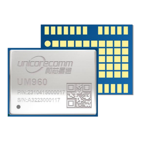
UNICORECOMM UM220-IV L User manual

UNICORECOMM
UNICORECOMM UM482 User manual

UNICORECOMM
UNICORECOMM UM220-IV M0 Programming manual

UNICORECOMM
UNICORECOMM UT4B0 User manual

UNICORECOMM
UNICORECOMM UM4B0 User manual

UNICORECOMM
UNICORECOMM UM220-IV M0 User manual

UNICORECOMM
UNICORECOMM UM4B0 User manual

UNICORECOMM
UNICORECOMM UM220-IV M0 User manual

UNICORECOMM
UNICORECOMM UM220-INS NF User manual

UNICORECOMM
UNICORECOMM UM980 User manual