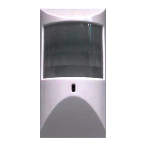
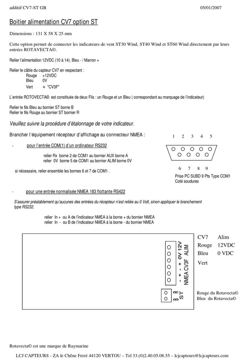
CityGrow CG500MS User manual

i
CG500MS
ZIGBEE PIR MOTION SENSOR
USER MANUAL
VERSION 1.1
17 JANUARY,2014
Disclaimers and Copyright
Nothing contained in this publication is to be construed as granting any right, by implication or otherwise, for the
manufacture, sale, or use in connection with any method, apparatus, or product covered by letters patent, or as
insuring anyone against liability for infringement of letters patent.
Efforts have been made to ensure the accuracy and reliability of the data contained in this publication; however,
Citygrow Energy Systems Limited. makes no representation, warranty, or guarantee in connection with this
publication and hereby expressly disclaims any liability or responsibility for loss or damage resulting from its use or
from the use of any product or methodology described herein; for any violation of any federal, state, or municipal
regulation with which this publication may conflict; or for the infringement of any patent from the use of this
publication. Nothing contained in this publication should be viewed as an endorsement by Citygrow Energy Systems
Limited. of any particular manufacturer’s products.
CG500MS
ZigBee PIR Motion Sensor

ii
CAUTION
RISK OF ELECTRIC SHOCK DO NOT OPEN
CAUTION: TO REDUCE THE RISK OF ELECTRIC SHOCK,
DO NOT REMOVE COVER (OR BACK) NO USER-SERVICEABLE
PARTS INSIDE REFER SERVICING TO QUALIFIED SERVICE PERSONNEL
The lightning flash with arrowhead symbol within an equilateral triangle is intended to alert the
user to the presence of uninsulated “dangerous voltage” within the product’s enclosure that may
be of sufficient magnitude to constitute a risk of electric shock to persons.
The exclamation point within an equilateral triangle is intended to alert the user to the presence
of important operating and maintenance (servicing) instructions in the literature accompanying
the product.
IMPORTANT SAFETY INSTRUCTIONS
READ BEFORE OPERATING EQUIPMENT
This product was designed and manufactured to meet strict quality and safety standards.
There are, however, some installation and operation precautions which you should be particularly aware of.
1. Read these instructions.
2. Keep these instructions.
3. Heed all warnings.
4. Follow all instructions.
5. Do not use this apparatus near water.
6. Clean only with dry cloth.
7. Do not block any ventilation openings. Install in accordance with the manufacturer’s instructions.
8. Do not install near any heat sources such as radiators, heat registers, stoves, or other apparatus that produce
heat.
9. Do not defeat the safety purpose of the polarized or grounding-type plug. If the provided plug does not fit into
your outlet, consult an electrician for replacement of the outlet.
10. Protect the power cord from being walked on or pinched particularly at plugs, convenience receptacles, and the
point where they exit from the apparatus.
11. Only use attachments/accessories specified by the manufacturer.
12. Use only with the cart, stand, tripod, bracket, or table specified by the manufacturer, or sold with the apparatus.
When a cart is used, use caution when moving the cart/apparatus combination to avoid injury from tip-over.
13. Unplug this apparatus during lightning storms.
14. Refer all servicing to qualified service personnel. Servicing is required when the apparatus has been damaged in
any way, such as power-supply cord or plug is damaged, liquid has been spilled or objects have fallen into the
apparatus, the apparatus has been exposed to rain or moisture, does not operate normally, or has been dropped.

1
Table of content
1. Introduction................................................................................................ 1
2. Understanding of the product ....................................................................... 2
3. Dimensions ................................................................................................. 3
4. Installation.................................................................................................. 4
5. Application notes......................................................................................... 7
5.1. Connect the PIR with external power supply ....................................... 7
5.2. Dry contact output and intelligent PIR sensing. ................................... 9
5.3. Tamper switch.................................................................................. 9
6. Clear Memory............................................................................................ 10
7. Specification.............................................................................................. 11

1
1. Introduction
Thank you for buying Citygrow’s product. CG500MS ZigBee PIR Motion Sensor is
designed for easy installation. The application can be home automation, energy
saving and security purpose.
Description
1. ZigBee wireless remote control.
2. Based on IEEE 802.15.4.
3. 2.4GHz radio frequency.
4. Motion detect to trigger a scene.
5. Scene setting can be a groups of light, curtain, AV, A/C, Fan…………etc.
6. Interface with iPhone, iPad and Android mobile devices.
7. Working with Citygrow’s HomeNET App.
8. LED indicator for power and status.
9. LED indicator can be disabled by jumper setting.
10. Power connector for external AC power supply.
11. Tamper switch protection.
12. Wall mount hanger for angle adjustment
13. Dry contact output terminal provided.
14. Easy to install.

2
2. Understanding of the product
Front cover
Main unit
Wall mount hanger
Main unit (bottom view)
Door
LED indicator
Program port
PIR Sensor Head
External power /
Dry contact
output connector
Tamper switch
LED jumper
1. External DC input +6V
2. GND
3. Dry contact output +
4. Dry contact output -
Screw
Battery compartment is for
storage of cable connectors
of CG101AD external power
supply
***Battery version is under
development**
Reset
Function

3
3. Dimensions
53mm
100mm
43mm
62mm
Main unit
Wall mount hanger
31mm
62mm
32mm

4
4. Installation
Step 1: Open the front cover by removing the fixing screw.
Step 2: Open the front cover.
Step 3: Connect the CG101UT5, CG101UTC cable from the program port to a PC
that installed with Citygrow’s HomeNET Planner Software.
Website to download: www.citygrowsys.com
Please note that you DO NOT need to insert the batteries or connect the product
with external power. During this setup process, the PC will power the product
through the cables.
Program port
CG101UT5 cable
CG101UTC cable
PC installed with HomeNET
Planner Software.
Window XP, Window 7

5
During the setup process with HomeNET Planner, two different processes are
needed. One is to assign the network ID to the PIR sensor, the second is to set the
scene / mood for home automation control. Please do not disconnect the cables
during the entire setup process.
Refer to the user manual of HomeNET Planner Software for setting up the product in
more details.
Step 5: After finishing all the setup steps with HomeNET Planner Software, please
unplug the cables and put the front cover back to the main unit and fix it with the
screw at the top of the product.
Step 6: Connect the CG101AD external power supply to the CG500MS. The LED
indicator will be ON for 2 seconds, if a motion is detected, the LED indicator will be
ON for 2 seconds again.
Step 7: Mount the PIR sensor at a location for your application. The following
diagram will show a typical example.
Warning!! This product is not designed for outdoor use. Install this product
indoor only. It is not suggested to locate this product close to big metal,
heat or strong radio sources.
Step 7.1: Select a location to mount the PIR sensor, the follow diagram will
show the PIR sensor range and angle.
0
5
15
10
35
30
25
20
2
4
6
8
feet
feet
12
O

6
Step 7.2: Mount the wall mount hanger on the wall
Step 7.3: Insert the PIR sensor into the wall mount hanger.
2.2M
typical installation

7
Step 8: Try a walk test and see the LED indicator is operating correctly or not. If a
motion is detected, the LED with be ON again for 2 seconds.
If everything is correct, remove the front cover again and remove the LED jumper.
(see section 2). Then, during normal operation, the LED indicator will not be ON
again.
5. Application notes
5.1. Connect the PIR with external power supply
You need to connect the PIR sensor with external power supply CG101AD, and so it
is no need to change the battery after a period of time.
5.1a. Connect the main power cable from the wall box to the Live and Neutral wires
of the CG101AD Mini Power Supply (purchase separately).
Make sure the Live is connected to the Brown wire (Live) and Neutral is connected to
Blue wire (neutral) of CG101AD.
CG101AD
Mini power
supply
Live (Brown)
Neutral (Blue)
DC6V output
“+” Red
“-“ Bl;ack
AC input
100 to 240V

8
5.1b. Plug the provided external DC power connector into the external DC socket and
route the cable according to the following diagram. Then connect the DC output of
the CG101AD to the external DC power connector, pay attention to the polarity of
the wires, black is GND, red is DC 6V.
Route the cable
DC6V
output from
CG101AD

9
5.1c. locate the wire connectors inside the recess area of the battery compartment
and address the cable before closing the door.
5.2. Dry contact output and intelligent PIR sensing.
When PIR detects moving object, it will send the wireless signal to Citygrow’s home
automation system to trigger a scene that may include lighting, curtain, AV
equipment, A/C …. Etc.
Secondly the dry contact output will also be triggered.
5.3. Tamper switch
When front cover is removed, the tamper switch will be activated. The dry contact
output will be triggered to become always at “high” level. The main unit will also
send the wireless signal to the home automation system. The action of the home
automation can be preset in HomeNET Planner Software. (Please refer to HomeNET
Planner User Manual).
Wire
connectors
Route the
wires

10
6. Clear Memory
In order to perform the Clear Memory function, please follow the below steps:
STEP 1
-
-Press and HOLD Function button
STEP 2
-CONTINUE holding onto the
Function Button.
-Press and release the Reset Button
once.
STEP 3
-Wait until the LED Indicator begins
BLINKING.
-Release the Function Button.
STEP 4
-Press and release the Function
Button again to stop blinking.
STEP 5
-Press and release the Reset Button.
-The memory inside of the product
has now been cleared.
Function
Reset
LED

11
7. Specification
Item
Specification
Power requirement
1. External DC6V input ( Powered by CG101AD AC input, DC output Mini
power supply)
ZigBee Wireless
communication
1. ZigBee wireless remote control.
2. Based on IEEE 802.15.4. standard
3. 2.4GHz radio frequency
RF communication
distance
100M ( open area)
PIR detection
1. Up to 5m radius at 25 deg C at 2.2m height
2. Up to 7m radius at 25 dec C at 5m height
** depending on the mounting, angle and temperature**
Operational
temperature
0 deg C to 40 deg C
Humidity
5% to 95% non-condensing
Storage
-20 deg C to 70 deg C
Dimension L X W x D
(mm)
100x53x43mm
Other manuals for CG500MS
1
Table of contents
Other CityGrow Accessories manuals
Popular Accessories manuals by other brands
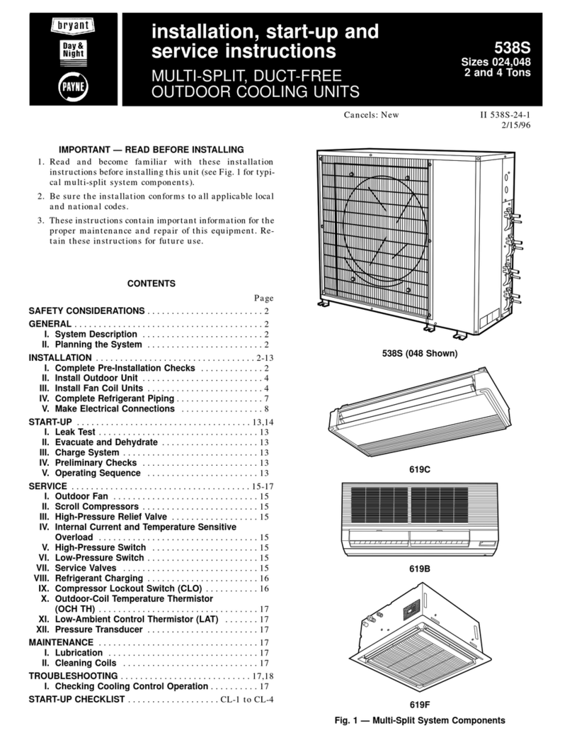
Bryant
Bryant 619B Installation, Start-Up and Service Instructions

Honeywell Home
Honeywell Home RDWL915W2000 Installation and operation guide

Swisher
Swisher PowerBlade PBY-5520 Assembly instructions
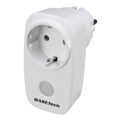
BASETech
BASETech 1710064 operating instructions

TP-Link
TP-Link tapo T310 user guide
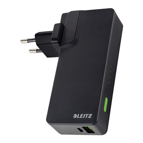
LEITZ
LEITZ 63070095 Instructions for use

Carmelli
Carmelli NG2515PB Assembly instructions
NEC
NEC MultiSync P551 Specifications
TigerTech
TigerTech Smart Doorbell user manual
Nevadent
Nevadent NMD 3.7 A1 operating instructions

Breville
Breville the BodyZone Plus Connect Instruction book
brennenstuhl
brennenstuhl Primera-Tec Automatic 19.500 A operating instructions
