CJ Spray 710 User manual
710 and 966 Turbine Spray Guns
Owner’s Guide & Parts List
CJ Spray, Inc.
6270 Claude Way East
Inver Grove Heights, MN 55076
1-888-CJSpray (888-257-7729)
SAVE THESE INSTRUCTIONS!
TM
Read andunderstand all instructionmanuals beforeoperating equipment.
For
ProfessionalUse Only. Observe
All
Warnings.
EQUIPMENT MISUSE
HaZARD
General Safety
Any misuse of the spray equipment or accessories,
such as improper usage, over pressurizing, modifying
parts, using incompatible chemicals and fluids, or
using wornor damaged parts,can
cause
themto rup-
ture and resultinserious injury, fire, explosion or
property damage.
Never point the spray gunat anyone or at any part
of the body.
System Pressure
This gun hasa
Marimum
Met
Fluid
Pressure of
100
psi (7 bar) anda
Maximum
lnletAir Pressure of
50
psi
(3.5 bar).
The
accessory remote pressure pots have a
Maximum
hletAir Pressure of
50
psi(3.5 bar). Never
exceed the maximum pressures of
the
gun, pressure
pot, or any other component or accessory usedinthe
system.
Never puthandorfingersoverthespraynozzle.PressureRelief
0
Nevertry tostop or deflectleakswithYourhandorThespray gun cups and accessory remote pressure
body.potsremainpressurized untilpressureismanually
Always turn
off
the air supplytothe gun before relieved. To reduce the risk of serious injury from
pressurizedfluidor accidental spray from the gun,
always relieve pressureinthe cupor pressurepot
removing the spraygun cup.
0
Check all spray equipment regularly and repair or before checking or servicing anypartof the spray
system; before installing, cleaning orchangingfluid
nozzles: before loosening or removing the accessory
replace wornor damagedpartsimmediately.
OnlyusegenuineGracoreplacementpartswhenremotepressure potcover;andwheneveryoustop
servicingthegun.spraying.
Never alter
or
modifyany part ofthis equipment:
doing
so
could causeit
to
malfunction.
Spray
Gun
Cup
Read and follow thefluidand solvent manufactur-
er’s literature regarding the use of protective
eyewear, gloves, clothing, respirator and other
equipment.
To
relieve pressure:
1. Turn
off
the air supplytothe gun.
2.
Unlatch the cup cover and loosen or remove the
cup from thecover.
FluidCompatibility
Be sureall fluids and solvents used are chemicallv
compatible with the “Welted Parts” showninthe
Technical Data on the backcover. Always read the
fluidand solvent manufacturer’s literature before
using thefluidor solventinthis gun.
Do
not usel,l,l-trichloroethane, methylene chloride,
other halogenated hydrocarbon solvents or fluids con-
taining such solventsinthe turbine spray system,
which contains aluminum and/or galvanized-coated
parts. Such usecould resultinaserious chemical
reaction, with thepossibilityof explosion, whichcould
cause death, serious injury, andlor substantial prop-
erty
damage.
Accessory
Remote
Pressure
Pot
To
relieve pressure:
1.
Turn
off
the air supplytothe pressure pot.
2.
2
1/2
Gallon Remote Pot:
Pull
the pressure relief
valve ring
(206c)
until pressure
is
completely
2
Quart Remote Pot: Turn
out
the pressure relief
relieved.
knob (113) about one turn. Waituntil pressure
is
completely relieved before removing the cover.
Close the knob before using the system again.
See Fig.
4
on page
7.
2
308-336

Tightenallfluid connectionssecurelybeforeeachuse.Handleandroutehosescarefully.Do notpullon
Never
use
adamaged hose. Before each use, check
the entire hose for cuts, leaks, abrasion, bulging
cover. or damaae or movement of the hose CouDlinw.
hosesto move equipment.
Do
not use fluidsor
sol-
vents which arenot compatible with theinner tube
and cover of the hose.
If
anyofthese conditionsexist, replace the hose
immediately.
.-
FIRE
OR
EXPLOSION
HAZARD
Sparking can be expected
inthe normal operation
of
.Sparkingand FlammableVapors
Hazard
IgnitionSources
Avoidallignition sources suchas static electricity
theturbinemotor.Sparkscouldignitefumesfromfromplasticdropcloths,openflamessuchaspilot
flammableliquid,dustparticlesandotherflammablelights,hotobjectssuch
as
cigarettes,arcsfromcon-
substancesinthesprayarea,andcauseseriousnectingordisconnectingpowercordsorturninglight
injury and property damage. Be suretofollow thepre . switchesonand
off.
Extinguishor remove all sources
cautionsbelow: ofignition.
When flammableliquid issprayed or used for
flushing or cleaning equipment, the turbine must
be placed at least
20
feet
(6.1
m) away fromareas
where hazardous concentrations of flammable
vapors arelikelyto occur.
Use
additionalair hose
if
necessary to ensure that
the turbine is operatedinaclean, dry, well venti-
latedarea.
Never place the turbine insideaspray booth!Use
this equipment outdoors or in extremely well venti-
latedareas.
To reduce the risk of static sparking, ground the tur-
Grounding
bine and all other spray equipment used or located in
the spray area. Check yourlocal electrical code for
detailed grounding instructions for your area and type
of equipment.
To
groundthe turbine: Plugthe power supply cord
intoa properly grounded outlet. Do not remove the
grounding prong from the power cord.Do notuse an
berated foraminimum of
15
amps.
adapter. Extension cords must have three wires and
IMPORTANT
United
States
Government
safety
standards
have
been
adopted
under
the
Occupational
Safety
and
Health
Act.
These
stan-
dards--particularly
the General Standards,
Part
1910
and
the
Construction
Standards,
Part
1926--should
be
consulted.
Table
of
Contents
Warnings..
....................................
2
Introduction
...................................
4
FluidSet Selection Charts
.......................
4
Shutdown
11
Setup..
6
SprayingTechniques
..........................
12
Maintenance..
................................
13
Service
......................................
16
.......................................
....................................
Troubleshooting..
.............................
18
Parts
Model710
................................
20
Models
709HS
&
71OHS
....................
22
Model71OP
...............................
24
Accessories
..................................
25
TechnicalData
........................
BackCover
Warranty
.............................
BackCover
308-336
3
Introduction
TheSeries
700
TurbineSprayGuncanspraymostanddirectsthepaintfrom thegun tothesurface,
coatings or finishes currently being used for automo-
tive
refinish, industrial, aerospace, marine, wood, minimizing overspray and increasing transferem-
plastic and architectural applications. ciency. This enables paintersto comply with new
clean air laws that are designedto reduce
VOC
(vola-
This spraygun typically utilizes
5
psi
(0.35
bar) tile organic compounds) emissions, eases paint
inbound air pressureto producehighquality paint application by requiring fewer paint passestoobtain
finishes. The gun producesacone of air that carries coverage, and savesonbothmaterial and clean-up
time.
Fluid
Set
Selection
Charts
Usingthe Charts
Unless otherwise ordered,theTurbine Spray Gun
size
of
thea/r cap, fluidnozzle, and fluid needle are
includesa
1.4
mmfluidset, part no.
M70581.
The
marked on theparts.
Use
the fluidset charts on page
5
to orderadifferent
size
fluid set ortofindthe part number of an indivi-
dual component of yourfluidset. The charts separate
fluid sets that are commonly usedincontractor
applications from those commonly usedinautomotive
applications.
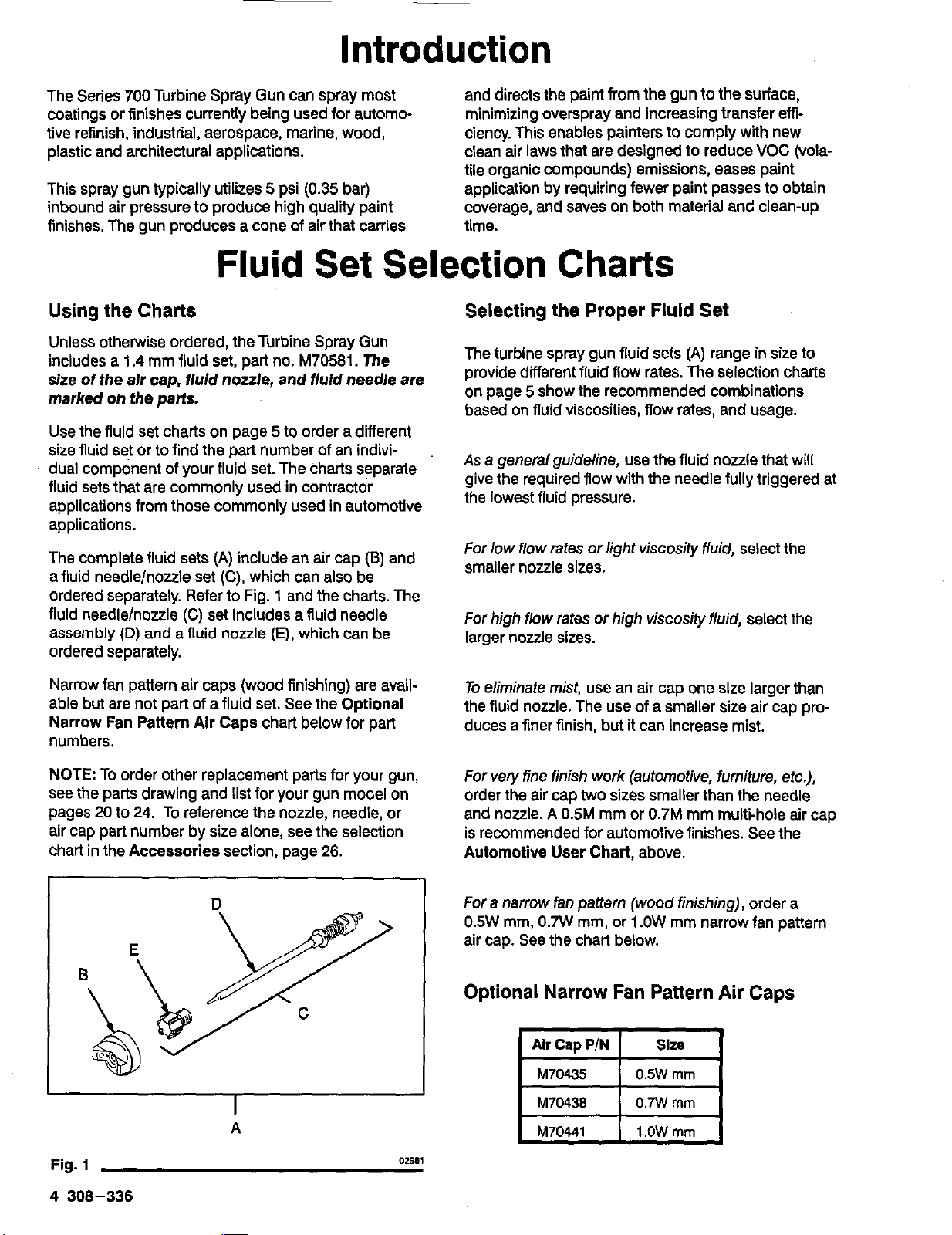
The completefluid sets
(A)
includean air cap
(a)
and
afluidneedlelnozzleset
(C),
which can also be
ordered separately. Referto Fig.
1
and the charts. The
fluidneedlelnoule
(C)
set includesafluid needle
assembly
(D)
and
a
fluid nozzle
(E),
which can be
ordered separately.
able but arenot partof afluid
set.
See the Optional
Narrow fan pattern air caps (wood finishing) are avail-
NarrowFan PatternAir Caps chart below for part
numbers.
see the parts drawing and list for your gun model on
NOTETo order other replacement parts for your gun,
pages
20
to
24.
To reference the nozzle, needle, or
air cappart number by
size
alone, seethe selection
chart in theAccessories section, page
26.
A
Fig.
1
02981
4
308-336
Selecting the Proper Fluid Set
The turbine spray gunfluidsets
(A)
rangeinsize to
provide differentfluidflow rates. The selection charts
on page
5
show the recommended combinations
based onfluidviscosities, flow rates, and usage.
As
ageneral guideline, use thefluidnozzle that will
the lowestfluidpressure.
give the required flow with the needle fully triggered at
For lowflow rates
or
lightviscosily fluid, select the
smaller nozzle sizes.
For
high
flow rates
or
highviscosity fluid, select the
larger nozzle sizes.
To
eliminate mist, use an air cap one size larger than
the fluidnozzle. The use ofasmaller size air cappro-
duces afiner finish,butitcan increase mist.
For very fine finish work (automotive, furniture, etc.),
order the air cap
two
sizes smaller than the needle
and nozzle.
A
0.5M
mm or
0.7M
mm multi-holeair cap
Automotive User
Chart,
above.
is recommended for automotive finishes. See the
Foranarrow
fan
pattern (wood finishing), ordera
0.5W
mm,
0.7W
mm, or
1
.OW
mm narrow fan pattern
air cap. Seethe chart below.
Optional Narrow Fan Pattern Air Caps
Alr
Cap
P/N
Slze
M70435
1
.OW
mm
M70441
0.7W
mm
M70438
0.5W
rnm
~
Fluid
Set
Selection
Charts
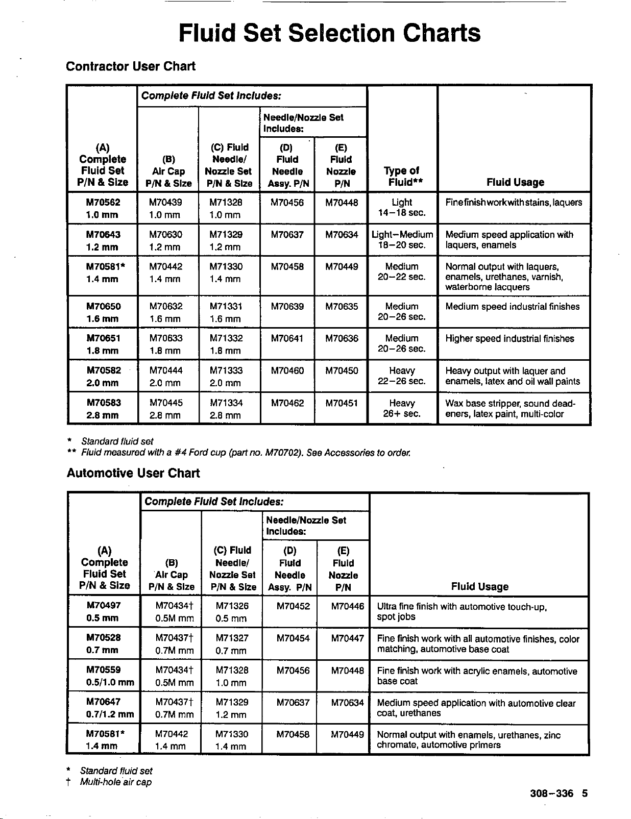
Contractor User Chart
I
Complete
Fluid
Set Includes:
NeedlelNozzleSet
(C)
Fluld
Needlel FluldFluld
(4
Complete
PIN
&
Size
Fluid Set
(6)
Alr
Cap
P/N
&
Slze
I
M71328M70456M704461.0 mm
M71329M70637M70634
M70439
1.0 mm
M70630
1.2 mm
M70442
1.4 rnm
Light
Finefinishworkwithstains,laquers
14-18 sec.
MediumNormaloutputwithlaquers,
waterborne lacauers
M70562
1.0
mm
M70643
1.2
mm
M70581'
1.4
mm
1.2 mm
I
M71330
I
M70456
I
M70449
1.4 mm
M70650
I
1.6mm
I
?ilz
I
I
M70632M70639M70635 1.6
mm
20-26 sec.
Medium Medium speed industrial finishes
I
M70651
I
M70633
I
M71332
I
M70641
I
M70636
1.8
mm
1.8 mm 1.8 mm 20-26 sec.
Medium Higher speed industrial finishes
I
M70444M71333
I
M70460
I
M70450
2.0
mm
22-26 sec. enamels, latex and oil wall paints
Heavy
I
Heavy output with laquer and
26+sec.eners.latexDaint.multi-color
Heavy
Wax
base stripper, sound dead-
I
M70583 2.8mm2.8
mm
2.8
mm
M70451 M70462
M71334 M70445
*
Standardfiuidset
**
Fluid
measured with
a
#4
Ford cup(part no.
M70702).
SeeAccessories to order:
Automotive User Chart
I
ComdeteFluidSetIncludes:
I
I
I
I
Includes:
I
~~
NeedleINoale
Set
(4
Complete
PIN
&
Size
Fluid Set
(C)
Fluld
PIN
Assv.
PIN
PIN
&
Slze NoaleNeedle
Noale
Set
Fluld
Fluld
Needlel
(E)
(Dl
(6)
'Alr
Cap
PIN
&
Slze
Fluid Usage
~ ~~~~
Ultrafine finish with automotive touch-up,
spot jobs
M70497 M70434t 0.5 mm
0.5
mm
0.5M mm M70446 M70452
M71326
~ M70437t
~ 0.7Mmm
M70434t
0.5M mm
M70437t
0.7M mm
M70442
1.4 mm
0.7
M71327
mm
I
M70454
M70447 Fine finish work with all automotive finishes, color
matching, automotive base coat
M70528
0.7
mm
M70559
0.511
.O
mm
M70647
0.711.2
mm
M70581*
1.4
mm
M70446 Fine finish work with acrylic enamels, automotive
base coat
M71328M704561.0 mm
1.2 mm
M71330M70458
M70634 Medium speed application with automotive clear
coat, urethanes
M70449 Normal output with enamels, urethanes, zinc
chromate, automotive primers
*
Standardfluidset
t
Multi-hole'aircao
308-336
5

Setup
Connect the Fluid
and
Air Supply
1.
Connect the gun air supply hose
(A)
between the
turbine air outlet
(D)
andthe gun air inlet. See
Fig. 2.
2.
If
using
aspray
gun
cup
(B),
connect the cupto
the gunfluidinlet.
3.
Musing
an
accessory remote pressurepot (C),
connect the fluid supply hose
(G)
between the
gun fluid inlet and the remote pressure pot.
Connect the air hose
(E)
between the pressure
potair inlet and the compressor air outlet
(F).
E
2-112
Gallon Remote Pressure Pot
Part
No.
M70604
(see
Accessories)
E
2
Quart Remote Pressure Pot
Part
No.
M70585
(see Accessories)
CX-8Turblne shown
Fig.
2
02859
6
308-336
Setup
Prepare the Fluid
1.
Always strain thefluid before spraying; this
includescolor, reducer and hardeners
if
used.
2.
When usingaturbine spray system, you need
to
usea slower drying reduceror thinnerto compen-
sate for the fasterdrying timecaused by the
warm air ofthe turbine.
Do
notover reduce.
PaintReduction
-
AutomotiveType Finishes
Reduce and catalyze all paintto manufacturer’s spec-
turbine systems, useareducer one-step slower than
ifications.To compensate for the faster drying time
of
what isused for conventional airspray.
PaintReduction
-
Industrial
or
DomesticCoatings
ifications.
If
noreductionsare given, first thoroughly
Reduce and catalyze all paintto manufacturer’s spec-
mix thefluid
to
be sprayed. Then gradually mixinthe
proper reducer,testing the fluid until youhave thecor-
rect spraying consistency.
To
test the consistency: Remove the stir stick from the
thinned paint.When the paint stream running
off
the
stir stick breaksintodroplets, the firstfew drops
should be about one second apart.
Fill
the Cup
or
Remote Pressure
Pot
Spray Gun Cup
WARNING
The spray gun cup is pressurized by the gun’s air
supply. To reduce the risk of serious injury from
pressurizedfluidor accidental spray from the gun,
always turn
off
the air supplytothe gun before
removing the spraygun cup.
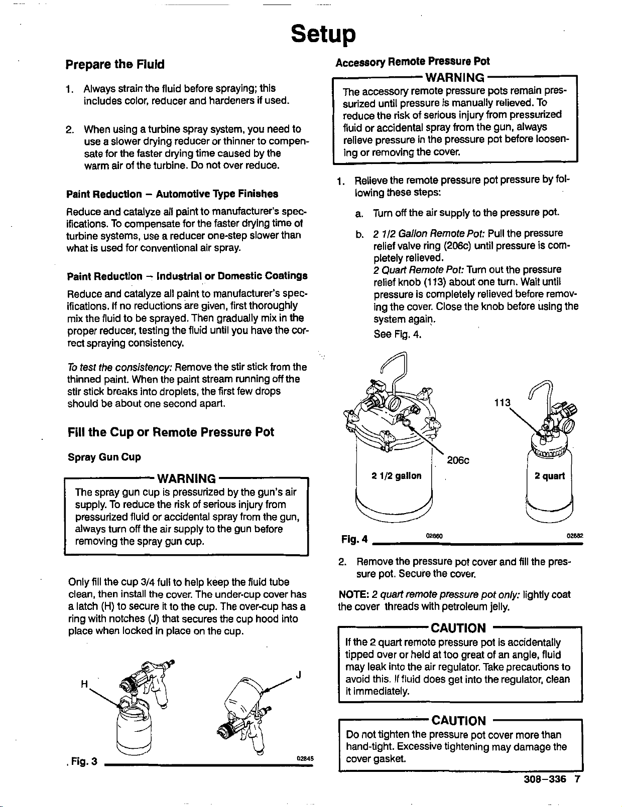
Only fill the cup
3/4
fullto help keep thefluid tube
alatch
(H)
to secure it to the cup. The over-cup hasa
clean, then install the cover. The under-cup cover has
ringwith notches
(J)
that secures the cup hoodinto
place when lockedinplace on the cup.
AccessoryRemotePressurePot
WARNING
The accessory remote pressure pots remain pres-
surized until pressureismanually relieved.TO
fluid or accidental spray from the gun, always
reduce the risk of serious injury from pressurized
relieve pressure in the pressure pot before loosen-
ingor removing thecover.
1.
Relieve the remote pressurepot pressurebyfol-
lowing these steps:
a. Turn
off
the air supply to the pressure pot.
b.
2
7/2Gallon Remote
Pot:
Pull the pressure
relief valvering (206c) until pressureiscom-
pletely relieved.
2
Quart Remote
Pot:
Turn out the pressure
relief knob
(113)
about one turn. Wait until
pressure
is
completely relieved before remov-
ingthe cover. Close the knob before using the
system again.
See Fig.4.
Fig. 4
2.
Remove the pressurepot cover andfill the pres-
sure pot.Secure the cover.
the cover threads with
petroleum jelly.
NOTE:
2
quart remotepressurepot
only:
lightlycoat
CAUTION
tipped over orheldat too great of
an angle,fluid
If the2 quart remote pressure pot
is
accidentally
may leakinto theair regulator. Take precautionsto
avoid this. Iffluiddoes getinto theregulator, clean
it immediately.
Do
not tighten the pressure pot cover more than
hand-tight. Excessive tightening may damage the
cover gasket.
308-336
7
Setup
Prepare the Surface
to
be Sprayed
To achieve proper adhesion, make sure the Surface
to
be sprayed
is
completely clean.
Operating the Turbine
WARNING
Sparking can be expectedinthe normal operation
of the turbine motor. Sparks could ignite fumes
from flammable liquid, dust particles and other
flammable substancesinthe spray area, and
cause seriousinjury and propertydamage. Be
sure
to
follow the precautions below:
0
When flammableliquid
is
sprayed or used for
flushingor cleaning equipment, the turbine
must be placed at least 20 feet
(6.1
m) away
from areas where hazardous concentrations of
flammable vapors are likely
to
occur.
0
Useadditionalair hose
if
necessary
to
ensure
that the turbine
is
operated inaclean, dry, well
ventilatedarea.
0
Never place the turbine insideaspray booth!
Use this equipment outdoors or in extremely
'
well ventilated areas.
0
Avoid all ignition sources suchas static eles-
tricity from plastic drop cloths, open flames
such aspilot lights, hot objects suchas ciga-
rettes, arcs from connecting or disconnecting
power cords orturning light switchesonand
off.
Extinguishor remove all sources of ignition.
1.
Turn the turbine onafew minutes before you start
spraying
to
allow for warm-up time. Turn the tur-
bine
off
when it
is
not inuse; it doesnot shut
off
automatically.
2. Be sure the turbine filter is clean before operating.
See
page
13
to
check and clean the filter.
Cold
Weather Operation
Turbine Spray ModelCX-8, CX-12, and CX-20 havea
diaphragm compressor. When these compressors are
new,the diaphragm will become
stiff
incoldweather.
If
cold enough, the stiff diaphragm will not allow the
compressor
to
start (theunit will hum).
If
thisoccurs,
follow these steps:
1.
Turnthe turbine and compressor
Off.
2. Unplug the turbine from the power source.
3.
Loosen the four main filter screws and remove the
filter; replace the main filter andprefilter
if
they
are dirty.
4.
Handspin the coolingfan on the compressor for
afew revolutions.
5.
Reassembletheturbine.
6.
Plug in the turbine and turn
it
on. The compressor
should start.
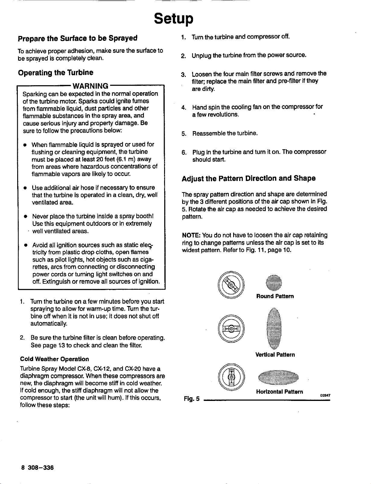
Adjust the Pattern Direction and Shape
The spray pattern direction and shape are determined
5.
Rotate the air cap as needed
to
achieve the desired
by the
3
different positions of the aircapshown inFig.
pattern.
NOTE
You do not have
to
loosen the air cap retaining
widest pattern. Refer
to
Fig.
11,
page
IO.
ring
to
change patterns unless the air cap
is
set
to
its
Round Pattern
Vertical
Pattern
Horlzontal
Pattarn
m817
Fig. 5
8 308-336

Setup
Adjust
the
Spray
Paitern
WARMING
FluidlnletPressure and
100
psi
(7
bar)
Maximum
Do
not exceed the gun's
50
psi
(3.5
bar)
Maximum
Air
inlet
Pressure. Higher pressurescan cause
partstorupture and resultinserious injury or
properlydamage.
L
To
establish the correctfluid
flow:
1.
Turnthefluidadjustment knob
(20)
counterclock-
wise until no restriction of the trigger movementis
felt. See Fig.
6.
u
Fig.
6
U
me45
2.
Ifa remote pressurepot
is
used, holdthe gun par-
alleltothe floor and adjustthe fluid pressureto
yield
a
12
to
18
inch
(305
to
457
mm) fluid stream.
See Fig.
7.
A
2
quart remote pressurepottypically should be
set at
2
to
4
psi
(0.14
to
0.28
bar).
A
2
1/2
gallonremote pressurepottypically
shouldbeset at
4to
8
psi (0.28to
0.56
bar).
Heavierfluidor a long fluidhose
will
require more
Dressure,
WARNING
To
reduce the risk of over-pressurizing the acces-
sory
remote pressure pots, which could cause
serious injury, never exceed
50
psi
(3.5
bar)
Maxi-
mum
Air
InletPressure.
Fig. 7
FluidVelocity
of
FluidNozzles
atthe Same FlowRate
m1u8
Orlflce
Size
In
Millimeters
Fig.
8
3.
if
further fluidadjustmentisneeded at the gun,
turn the fluid adjustment knob
(20)
clockwiseto
reduce the volume
of
fluid output and obtain the
desired results. See Fig.
9.
02849
20
U
Fig.
9
me45
CAUTION
continuously spraying
with thefluid adjustment
Restricting the trigger
and fluidneedle travel by
knob closed (turned clockwise), will cause
accelerated abrasive wear on thefluid needleand
wear onthe trigger.
Forthe best results, adjust the fluid flow at the
nozzlelair cap combination.
pressure source or useadifferent
size
needle/
308-336
Setup
Adjust
the Spray Pattern
(continued)
To
establish thecorfectair
flow:
4.
Test the spray pattem and atomization while hold-
ingthe gun about
6
to
8
inches(150 to
200
mm)
from the test piece.
5. The Air ControlValve
(M)
on the end of thetur-
bine hose controls both the atomizing air and the
pressureinthe spray gun cup (if used). See Fig.
10.
Adjust the aircontrolvalve
as
needed.
M
Fig.
10
NOTES
To
control over-spray mist, use onlyas much airas
02850
isnecessary for thefluid being sprayed.The
lighter the fluid, the
less
air required.
If
atomization
is
unacceptable after following the
further ora differentfluidset maybe required.
procedure above, thefluidmay need
to
be thinned
Refer
to
pages
4
and
5
to select the proper fluid
set
or
page
7
toprepare the fluid.
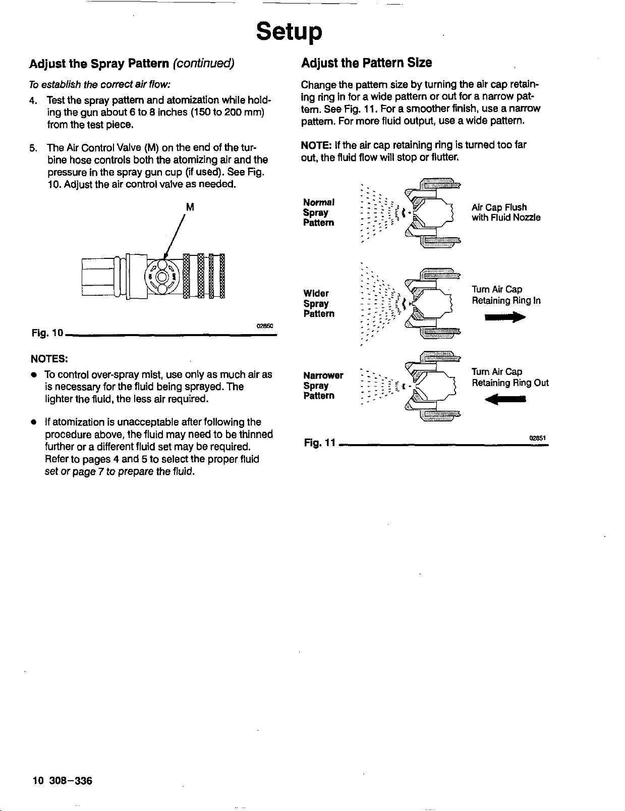
Adjust
the
Pattern
Size
Change the pattem sizebyturning theair cap retain-
tern. See Fig. 11. Fora smoother finish, use a narrow
ing ringinfor a wide patternor out for a narrow pat-
pattern. For morefluidoutput,use a wide pattern.
NOTE
If
the aircap retainingring
Is
turned
too
far
out, the fluid flowwillstop or flutter.
Normal
Pattern
Spray
Wider
Spray
Pattern
Narrower
spray
Pattern
Air Cap
flush
with
Fluid Nozzle
Turn
Air
Cap
Retaining RingIn
c
Turn Air Cap
RetainingRing
Out
-
Fig.
11
02851
10
308-336
Shutdown
WARNING
The spray gun cups and accessory remote pres-
sure pots remain pressurized until pressure is
manually relieved.To reduce the risk of serious
injury from pressurized fluid or accidental spray
from the gun, always relieve pressureinthe cup or
pressurepotbefore checkingor servicingany part
of the spray sysfem; before installing, cleaning or
changing fluidnozzles: before loosening or remov-
ingthe accessoly remote pressure potcover; and
whenever you stop spraying.
1.
When spraying
is
finished, turn
off
the air supply
tothe gun.
2.
If
usingaremote pressure pot, relieve
its
pressure
by following thesesteps:
a. Turn
off
the air supplytothe pressure pot.
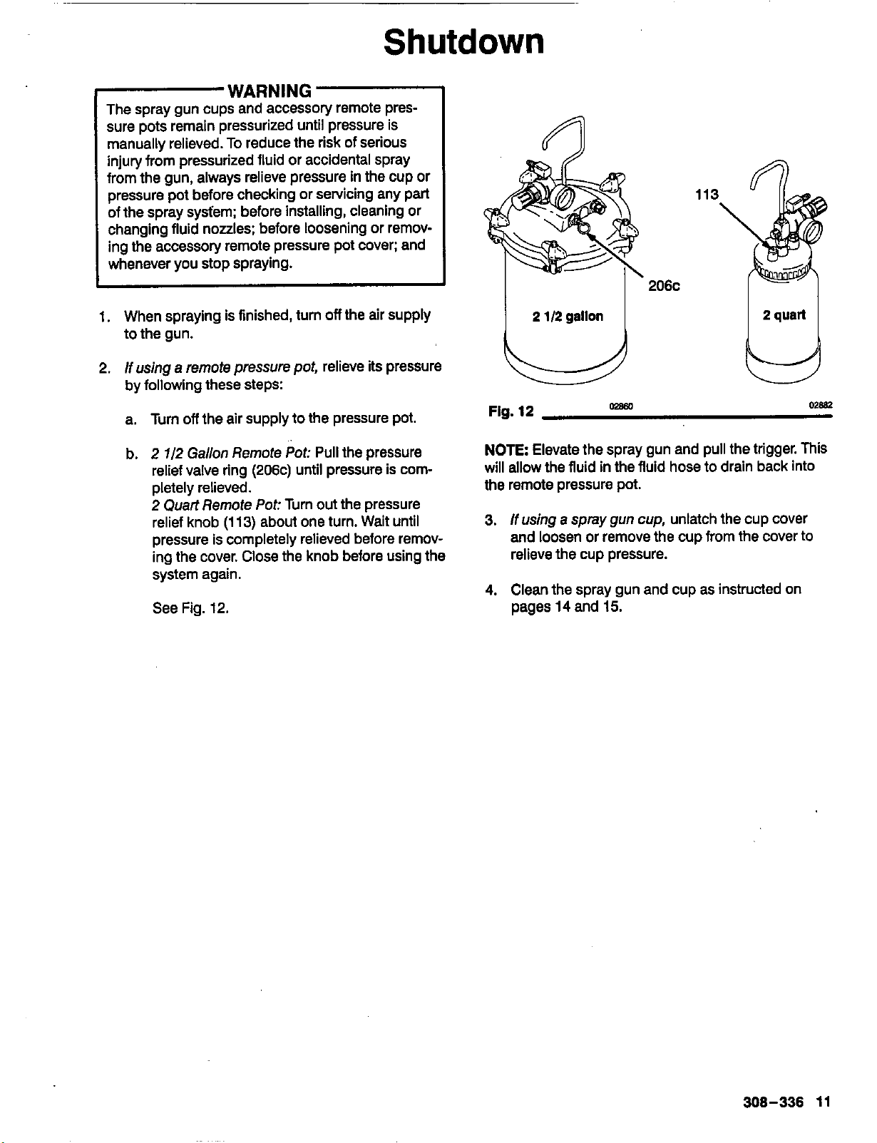
b.
2
1/2
Gallon Remote
Pot:
Pull
the pressure
relief valvering (206c) until pressure
is
com-
2
Quart
Remote
Pot:
Turn
out
the pressure
pletely relieved.
relief knob
(1
13)
about one turn. Wait until
pressure
is
completely relieved before remov-
ingthe cover. Close theknobbefore using the
system again.
See Fig. 12.
113
206c
ULJ
2
1/2
gallon
Fig.
12
NOTE
Elevate the spray gun and pull the trigger.
This
will allow thefluidinthefluidhose to drain back into
the remote pressure pot.
3.
If
using
a
spray gun cup, unlatch the cup cover
and loosenor remove the cup from the cover to
relievethe cuppressure.
02860
MBB2
4.
Clean the spray gun and cupas instructed on
pages14and
15.
308-336
11
Spraying
Techniques
General Spraying Techniques
1.
Select the proper fluid set for thefluidyou are
spraying.See pages
4
and
5.
2.
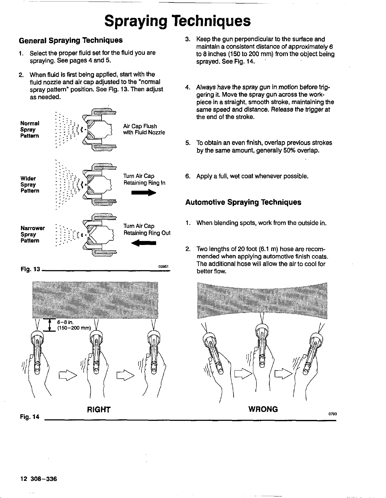
Whenfluid
is
first being applied, start with the
fluidnozzle and air cap adjustedtothe "normal
spray pattern" position.
See
Fig.
13.
Then adjust
as needed.
Normal
spray
Pattern
Wider
Pettern
Spray
Air
Cap
Flush
with
Fluid
Nozzle
Turn
Air
Cap
Retaining
Ring
In
-
Turn Air Cap
Retaining
Ring
Out
-
Fig.
13
02851
3.
Keep the gun perpendicular
to
the surface and
to
8
inches
(150
to
200
mm) from the object being
maintainaconsistent distance
of
approximately
6
sprayed. See Fig.
14.
4.
Always have the spray guninmotion beforetrig-
gering
it.
Move the spraygun across the work-
pieceinastraight, smooth stroke, maintaining the
the end of the stroke.
same speed and distance. Release the trigger at
5.
To obtainan even finish, overlap previous strokes
by the same amount, generally
50%
overlap.
6.
Apply afull, wet coat whenever possible.
Automotive Spraying Techniques
1.
When blending spots, work from the outside in.
2.
Two lengths
of
20
foot
(6.1
m) hose are recom-
mended whenapplying automotive finish coats,
The additional hose will allow the airto coolfor
better flow.
RIGHT
WRONG
0783
12
308-336
~~
Spraying
Techniques
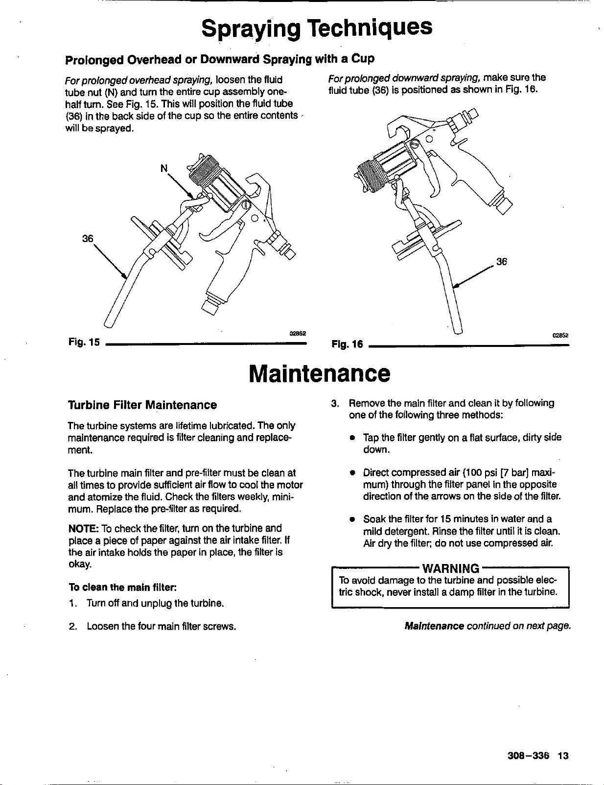
Prolonged Overhead or Downward Sprayingwith a
Cup
For
prolongedoverhead spraying, loosen thefluid
tube nut
(N)
and turn theentire cup assembly one-
half turn. See Fig.
15.
This willposition the fluid tube
(36) inthe back side of the cup
so
the entire contents
I
will besprayed.
36
Fig.
15
Forpro/ongeddownwafd spraying, make sure the
fluid tube(36)
is
positioned
as
shown inFig. 16.
W2
Flg.
16
Turbine Filter Maintenance
The turbine systems are lifetime lubricated. The only
maintenance requiredisfilter cleaning andreplace
ment.
The turbine main filter and pre-filter must be cleanat
all times
to
provide sufficient air flowtocoolthe motol
and atomize the fluid. Check the filters weekly, mini-
mum. Replace theprefilteras required.
NOTE
To
check the filter, turn on the turbine and
the air intake holds the paperinplace, the filter
is
placeapiece of paper against the air intake filter.
If
okay.
To
clean themainfilter:
1.
Turn
off
and unplugthe turbine.
2.
Loosen the four main filter screws.
3.
Remove the main filter and cleanit by following
one ofthe following three methods:
0
Tap the filter gently onaflat surface, dirty side
down.
0
Direct compressed air
(100
psi
[7
bar] maxi-
direction of the arrows on the side of the filter.
mum) through the filter panelinthe opposite
0
Soak thefilter for
15
minutesinwater anda
Air drythe filter; do not use compressed air.
milddetergent. Rinse the filter untilit
is
clean.
-
WARNING
To avoid damage
to
the turbine and possible elec-
tric shock, never installadamp filterinthe turbine.
Maintenancecontinued on
next
page.
308-336
13
Maintenance
WARNING
The spray gun cups and accessory remote pres-
sure pots remain pressurizeduntilpressureis
manually relieved. To reducethe risk of serious
injury from pressurized fluid or accidental spray
from the gun, always relieve pressureinthe cupor
pressure pot before checkingor servicingany part
of the spray system; before installing, cleaning or
changingfluidnozzles; before loosening or remov-
whenever you stop spraying.
ing the accessory remote pressure pot cover; and
NOTES
0
Check forany fluid leakage from the gun and fluid
hoses. Tighten fittingsor replace equipmentas
needed.
Flush the gun before changing colors and when-
ever youare done spraying.
CAUTION
fluid being sprayed and compatible with the spray
Clean all parts witha solvent Compatible with the
gun and cup or accessory remote pressurepot
wetted parts. See theTechnical
Data
on the back
cover.
Flushing the Spray Gun Using
a
Remote
Pressure Pot
1.
Turn
off
the air supplyto the gun.
2.
Relievethe pressure pot pressure by following
these steps:
a. Turn
off
the air supplyto the pressure pot.
b.
2
7/2
Gallon
RemotePot: Pull the pressure
relief valvering (206c) until pressure
is
com-
2
Quart
Remote
Pot:
Turn out the pressure
pletely relieved.
relief knob
(113)
about one turn.Wait until
pressure
is
completely relieved before remov-
ing the cover. Close the knob before using the
system again.
See Fig.
12,
page
11.
3.
Fill the pressure potwith compatible solvent.
4.
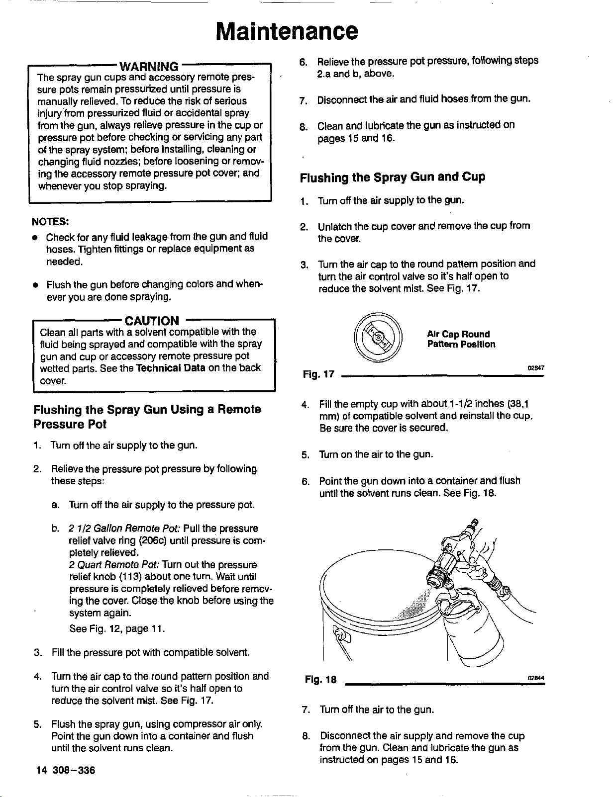
Turn the air cap tothe roundpattern position and
turn theair controlvalve
so
it's
haif opento
reduce
the
solvent mist. See Fig.
17.
5.
Flush the spray gun, using compressor air only.
Point thegun downintoacontainer and flush
until the solvent runs clean.
14
308-336
6.
Relievethe pressurepotpressure, following
steps
2.a and b, above.
7.
Disconnect the air and fluid hoses from the gun.
8.
Clean and lubricate
the
gun
as
instructed on
pages
15
and
16.
Flushingthe Spray Gun
and
Cup
1.
Turn
off
the air supplytothe gun.
2.
Unlatch the cup cover and remove the cup from
the cover.
3.
Turn the air captothe round pattern position and
turnthe aircontrolvalve
so
it's half opento
reduce the solvent mist.
See
Fig.
17.
@
Alr
Cap
Round
Pattern
Posltlon
Fig.
17
1
me41
4.
Fill the emptycupwith about
1-1/2
inches
(38.1
mm)
of
compatible solvent and reinstall the cup.
Be surethe cover
is
secured.
5.
Turn on the air to the gun.
6.
Point thegun downintoacontainer and flush
until the solvent runs clean. See Fig.
18.
Fig.
18
028u
7.
Turn
off
the air to thegun.
8.
Disconnect the air supply and remove the cup
from the gun. Clean and lubricate the gunas
instructedon pages
15
and
16.

Maintenance
Clean the SprayGun
4.
Soak the air cap, detent plate and fluid nozzlein
solvent. Clean the air car, andfluid nozzle daily,
.~
1.
Clean the gun and cup by hand witha compatible minimum, with solvent and the brush (R), pro-.
solvent or place themina gunwasher with the vided. See Fig.
21.
Some applications require
trigger held open; cycle thewasher as necessary more frequent cleaning. Keep all air cap holes
toclean the gun. clean.
CAUTION
toavoid permanently damaging them.
Clean aircap horn holes withanon-metallic item
R
Fig.
19
Me53
2.
Remove the air cap retaining ring
(29),
air cap
20.
(27).
spring
(25),
and detent plate (26). See Fig.
3.
Trigger the gun while you remove the fluid nozzle
Fig.
20.
(19)
with
the
nozzle wrench
(P),
provided. See
CAUTION
Trigger thegunwhenever you tightenor remove
the nozzle. This keeps the needle seatawayfrom
the nozzle seating surface and prevents the seat
from being scratched.
Fig.
20
OW
Fig.
21
5.
With the gun pointed down, clean the frontof the
02858
gun, using thebrush, and solvent.
6. Trigger the gun while you install the fluid nozzle
(19)
with the nozzle wrench
(P).
See Fig. 20.
7. Install the spring (25)into the frontof the gun.
8.
Install the detent plate (26)into the gun housing
with its open sockets
(S)
facing up; align the det-
ent plate tab
0
with the notchinthe gun hous-
ing. See Fig.
22.
9.
Install the air cap
(27),
aligning theair cap balls
(U)
with the detent plate sockets
(S).
See
Fig. 22.
Secure the air cap with the air cap retainingring
(29).
NOTE
If
installed correctly, the air cap will snapinto
4
definite positions, with no loose rotation between the
positions.
n
%===??=
Fig.
22
10.
Lubricate the gun after cleaning
it
as instructedon
M968
page
16.
308-336
15
Service
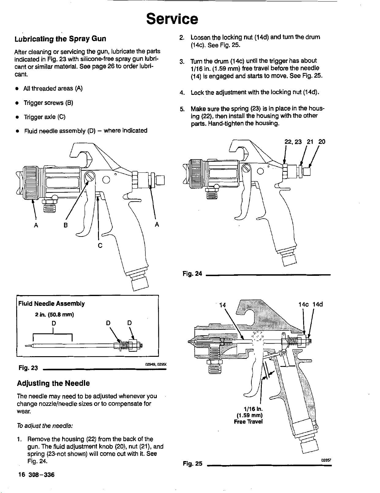
Lubricating the Spray
Gun
After cleaning or servicing the gun, lubricate the parts
indicated in Fig.
23
with silicone-free spray gun lubri-
cant or similar material. Seepage
26
to order lubri-
cant.
0
All
threadedareas(A)
0
Triggerscrews
(8)
0
Trigger
axle
(C)
0
Fluid needle assembly
(D)
-
where indicated
2.
Loosen thelocking nut(14d) andturnthe drum
(14c). See Fig.
25.
3.
Turn the drum(14c) until the trigger has about
1/16in.
(1.59
mm) free travel before the needle
(14) isengaged and startsto move. See Fig.
25.
4.
Lock the adjustment
with
the locking nut (14d).
5.
Make
sure
the spring
(23)
is
inplaceinthe hous-
ing
(22),
then install the housing with the other
parts. Hand-tighten the housing.
~
Fluid
Needle
Assembly
2
in.
(50.8
mm)
02949.
om
Fig.
23
Adjusting theNeedle
The needle may needto be adjustedwhenever you
change nozzle/needle sizes orto compensate for
wear.
To
adjust
the
needle:
1.
Remove the housing
(22)
from the back of the
gun. Thefluid adjustment knob
(20),
nut
(21),
and
spring (23-not shown) will come out with it. See
Fig.
24.
16308-336
Fig.
24
Fig.
25
02857

Service
Adjusting
the Needle
Packings
The needle packings require adjustment once a
month under normal usetoensure fluid does not leak
back throughtheneedle packings. The needle pack-
ings must alsobeadjusted whenever
the
needle
is
removed or adjusted.
To
adjust the needle packings:
1.
First flush thegunas instructed on page
14.
2.
Remove the air cap retainingring
(29),
air cap
26.
(27),
spring
(25),
and detent plate
(26).
See Fig.
3.
Trigger the gun while you remove the fluid nozzle
Fig.
26.
Clean the gun as instructed on page
15.
(19)
with the nozzle wrench
(P),
provided. See
ICAUTIOY
1
Trigger the gun whenever you tighten or remove
the nozzle. This keeps the needle seat away from
the nozzle seating surface and prevents the seat
from beina scratched.
K
98
5.
Trigger the gun while you install the fluid nozzle
(19)
with the nozzle wrench
(P).
See Fig.
26.
6.
Install the spring
(25)
into the front of the gun.
7.
Install the detent plate(26) into the gun housing
withitsopen sockets
(S)
facing
up;
align the det-
ent plate tab
0
with the notchinthe gun hous-
ing. See Fig.
28.
8.
Install the air cap
(27),
aligning the air cap balls
(U)
with the detent plate sockets
(S).
See Fig.
28.
Secure the aircapwith the air cap retaining ring
(29).
Fig.
26
4.
Trigger the gun while you turn the packing
nut
(9)
slightly clockwise with the packing wrench
(K),
provided.
See
Fig.
27.
This will compress the
packings.
The packings need very
little
pressure to
seal
tight; back the packing nut
off
1/16
turn. The
well. If the needle binds, the packings are
too
are over-tightened, they maybedamaged and
needle should then move freely. If the packings
need toberemoved and replaced.
02854
NOTE
If installed correctly, the air cap will snap into
4
definite positions, withnoloose rotation between the
positions.
Fig.
28
02868
308-336
17
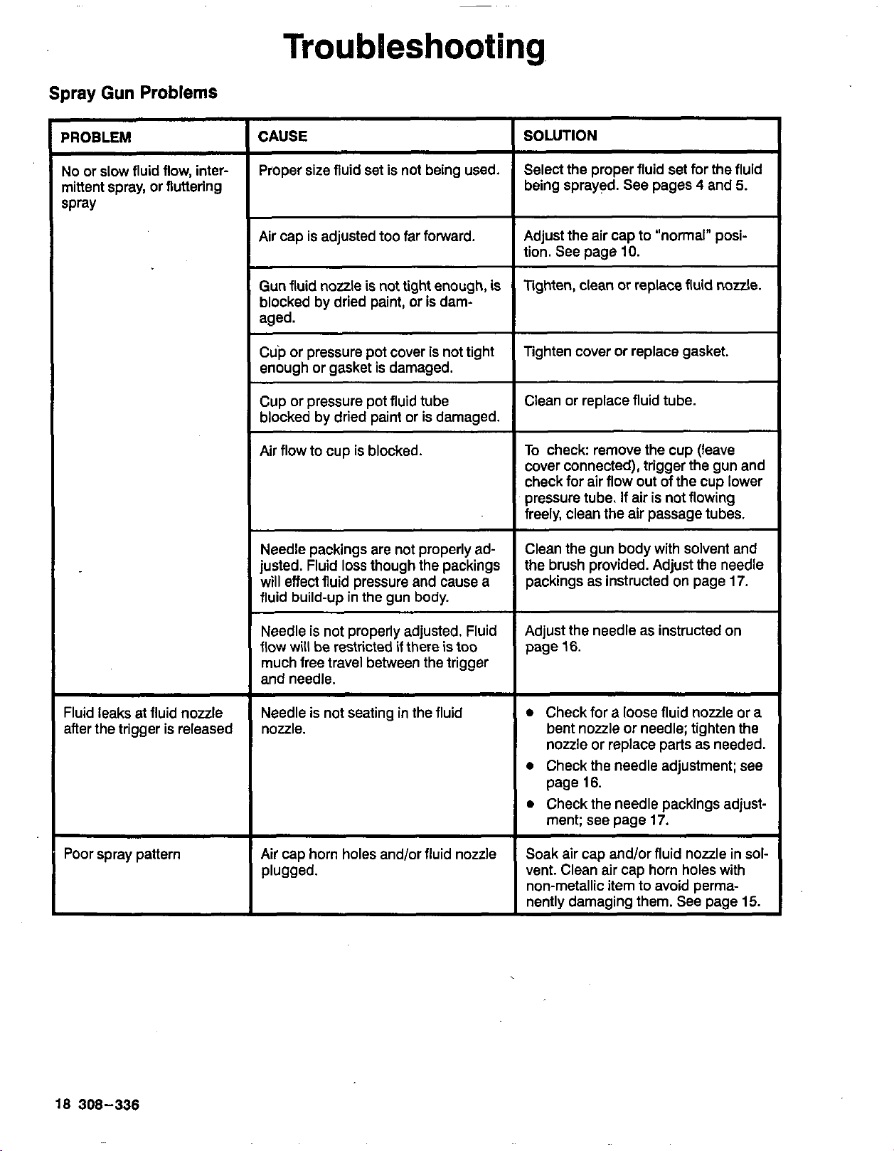
Troubleshooting.
Spray
Gun
Problems
PROBLEM
No or slow fluid flow, inter-
mittent spray, or fluttering
spray
Fluid leaks at fluid nozzle
after the trigger is released
Poorspray pattern
CAUSE
Proper size fluid setisnot beingused.
Air cap is adjusted too far forward.
Gun
fluid
nozzle
is
not tight enough,is
aged.
blocked by dried paint,
or
isdam-
Cup or pressure pot cover is not tight
enough or gasket is damaged.
Cup or pressure pot fluid tube
blocked by dried paint or is damaged.
Air flowto cupis blocked.
Needle packings are not properly ad-
justed. Fluid
loss
though the packings
will effect fluid pressure and cause a
fluid build-upinthe gun body.
flow willberestricted if thereis too
Needle is not properly adjusted. Fluid
much free travel between the trigger
andneedle.
Needle is not seatinginthe fluid
nozzle.
Air cap horn holes and/or fluid nozzle
plugged.
SOLUTION
Select the proper fluid set for the fluid
being sprayed. See pages
4
and
5.
tion. See page
10.
Adjust the aircap
to
"normal" posi-
Tighten, clean or replace fluid nozzle.
lightencover or replace gasket.
Clean or replace fluid tube.
To
check: remove thecup (leave
cover connected), trigger the gun and
check for air flow out of thecuplower
freely, clean the air
passage tubes.
pressure tube.
If
air
isnotflowing
Clean thegunbody with solvent and
the brush provided. Adjust the needle
packingsas instructed on page
17.
Adjust the needle as instructed on
page
16.
0
Check for
a
loose fluid nozzle or
a
bent nozzleor needle; tighten the
nozzle or replace parts as needed.
0
Check the needle adjustment; see
page
16.
0
Check the needle packings adjust-
ment; see page
17.
Soak air cap and/or fluid nozzlein
sol-
vent. Clean air cap horn holes with
non-metallic itemtoavoid perma-
nently damaging them.See page
15.
18
308-336
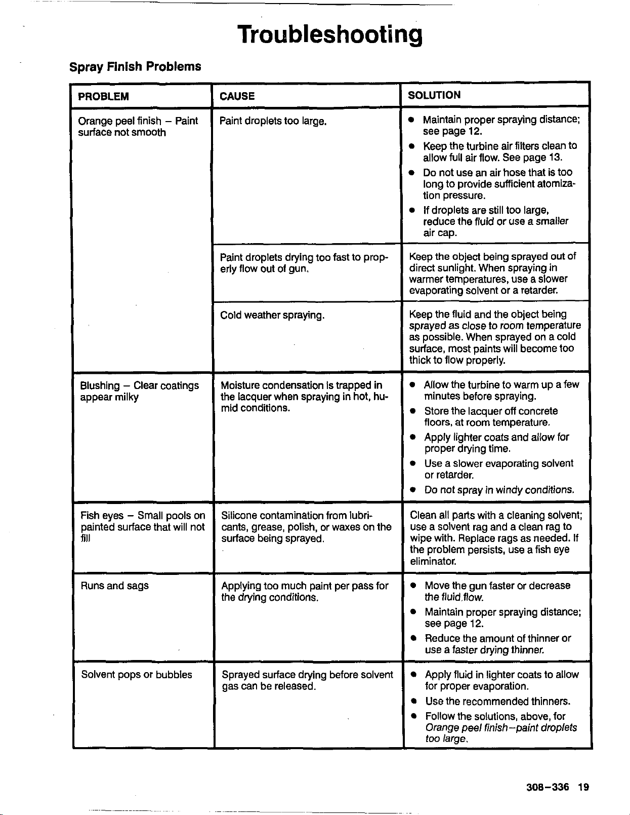
Troubleshooting
Spray
Finish
Problems
'ROBLEM
-
)range peel finish
-
Paint
iurfacenotsmooth
3lushing
-
Clear coatings
appear milky
Fish eyes
-
Small pools on
painted surface that will not
fill
Runsandsags
Solvent pops or bubbles
~ ~~
CAUSE
Paint droplets too large.
Paint droplets drying too fasttoprop-
erly flow out of gun.
Cold weather spraying.
~~~ ~~~
Moisture condensationistrapped
in
the lacquer when spraying
in
hot, hu-
mid conditions.
Silicone contamination from lubri-
cants, grease, polish, or waxeson the
surface being sprayed.
Applying too much paint per pass for
the
drying
conditions.
Sprayed surface drying before solven
gas can be released.
SOLUTION
Maintainpropersprayingdistance:
see page
12.
Keeptheturbine air filters clean to
allow
full
air flow. See page
13.
Do
not use an air hose that isto0
longtoprovide sufficient atomiza-
tion pressure.
reduce the fluidoruse a smaller
air cap.
If droplets are still too large,
Keep
the
object being sprayed out of
direct sunlight. When sprayingin
warmer temperatures, use a slower
evaporating solvent or a retarder.
Keepthe fluid and the object being
sprayed as close
to
room temperature
as possible. When sprayed on a cold
surface, most paints will become too
thicktoflow properly.
Allow the turbinetowarm upa few
minutes before spraying.
Store the lacquer
off
concrete
floors, at room temperature.
Apply lighter coats and ailow for
proper drying time.
Use a slower evaporating solvent
or retarder.
Do
not spray
in
windy conditions.
Clean all parts with a cleaning solvent:
wipe with. Replace rags as needed. If
use a solvent rag and a clean rag to
the problem persists, use a fisheye
eliminator.
Move the
gun
faster or decrease
Maintainpropersprayingdistance:
Reduce the amount of thinner or
the fluid.flow.
see page
12.
use a faster drying thinner.
Apply fluidinlighter coatstoallow
Use the recommended thinners.
Follow the solutions, above, for
for proper evaporation.
Orangepeelfinish-paint droplets
too large.
308-336
19

2
18
19
20
21
Parts for 966 Gun
17
This manual suits for next models
1
Table of contents


