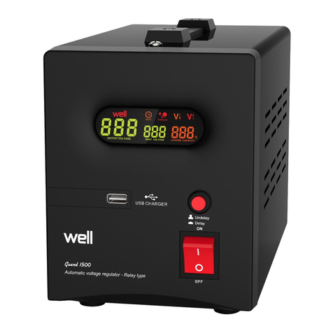
CKvision CK-HDT24-70W-4DT User manual

Please be careful before use
Read this instruction manual
Digital light source controller
CK-HDT24-70W-4DT

Digital light source controller
Features
CK-HDT24-70W-4DT
K-HDT24-70W-4DTIt is a four-way high-power multi-function light source controller, with two light
source driving modes: splash screen and long light, multiple function settings, easy to use.
1.Single channel with load output current up to 1A
2.Provide knob/serial communication mode to control brightness
3.The serial port can provide a total of 256 levels of brightness adjustment from 0 to 255
4.The external trigger adopts optocoupler isolation design to provide accurate
5.With power-down save, overload/short circuit protection function
01
Specification Description
02
1
Specification description
Constant pressure
256-level PWM control
Panel knob/RS232
120KHz PWM
AC100-240V 50/60Hz
4
24V
1A
72W
DC5V~24V(Current approximately 5.6mA)
<30μs(Load-related)
Temperature:0~40℃、humidity:20~85%RH(Non-condensing)
Temperature:-20~60℃、humidity:20~85%RH(Non-condensing)
Natural cooling
Item
Drive mode
Dimming method
PWM frequency
Input voltage
channel
Output voltage
Maximum output current
Maximum output power
External trigger voltage
Trigger delay
Use temperature and humidity
Store temperature and humidity
Cooling method

1.Power switch:
Three-head socket at the left end, connected to AC input, input voltage range AC100-240V
50/60Hz;Turn the switch on the right end to "0" to turn off the main power supply, and turn it to
"1" to turn on the
2.RS232 Interface:
Connect the serial communication cable to the host computer, through the CKvision builder
can adjust the brightness of the light source and soft trigger。
· Protocol:RS232
· Baud rate: 115200
· control method:Control how text is sent via CKvision builder
· I96,I97,I98,I99 Corresponding to 1 to 4 channels respectively;
· Values from 1 to 256 are brightness adjustment values
For example:
1. Adjust the brightness of the first channel to 200
Send "I96=200 SAVEI Enter" directly
2.Adjust the brightness of each channel to 100
send directly ”I96=100 I97=100 I98=100 I99=100 SAVEI Enter”。
3.Trigger input port :
The four trigger inputs, in order, are TG1、TG2、TG3、TG4。The trigger signal of each channel is
connected to the corresponding "+" terminal, and the negative is connected to the
corresponding "-" terminal。
Ntroduc�on to use:03
一、Introduc�on to the func�ons of each area of the panel
2
4.Trigger output
3.Trigger input port
1.Power switch
2.RS232 interface
6.Status indicator
5.Digital display
7.Knob with key function
PUSH/CONTROL
10.Four-way light
source interface
8.Locking (LOCK/
UNLOCK) toggle switch
9.Trigger input pulse
rising edge/falling edge
Valid selection switch

The controller receives the rising edge/falling edge signal of the pulse of the trigger port (can
be selected by the switch of serial number 9), the controller drives the light source of the
corresponding serial number, and outputs the pulse signal to the corresponding trigger output
(CAMERA) port, triggering the camera to take pictures。
4.Trigger output:
According to the received input signal of the corresponding channel, trigger output, the
amplitude of the output pulse is 12v, the output is connected to the positive end of "CAMERA
trigger input", and the negative output is connected to the negative end of "CAMERA trigger
input". Drive capability greater than 100mA。
5.Digital display:
Four-digit seven-segment digital display, showing the channel number and the
corresponding brightness value; the first one on the left Display the channel number, the right
three display the brightness value, the range:0⸺255.
6.Status indicator:
· H/L instruction :Effective switching of rising edge/falling edge;
· ERR instruction : System error message;
· LOCK instruction:Set lock indication;
7.Knob with key function PUSH/CONTROL
· Press the button once, the channel switches once。
· The knob adjusts the brightness value of the light source, turn clockwise, the brightness
increases; turn counterclockwise, the brightness decreases。
8.Locking (LOCK/UNLOCK) toggle switch
· When the switch is turned to LOCK, the brightness cannot be modified and adjusted at this
time, and the light source controller enters the trigger working mode;
· Switch to the UNLOCK state, at this time you can set the brightness of different channels
through the button knob。
· Save Settings: After setting the brightness of all channels, switch the display to 4
Channel When, after pressing the knob button for a long time for 5s, hit the “8 lock switch” from
UNLOCK to LOCK, and the save is complete.。
9.Trigger input pulse rising edge/falling edge Valid selection switch:
When the switch hits "HIGH", the rising edge trigger is valid; when the switch hits "LOW" mode,
the falling edge trigger is valid。
10.Four-way light source interface
The light source interface sequence, from top to bottom, is CH1, CH2, CH3, CH4
corresponding to the trigger input and output serial numbers。
3

This digital light source controller has two working modes:
long light and splash screen:Long light mode, that is, after the controller receives a valid
trigger signal (rising edge/falling edge)Continue to drive the light source, and stop driving the
light source until the reverse change of the trigger level is detected。
In the splash screen mode:the controller receives a valid trigger signal (rising edge/falling
edge), drives the light source of the corresponding serial number to light up for 1.2ms, and
outputs the trigger signal to the corresponding trigger output port。
Mode switch:
Switch from long light to splash screen mode: press the PUSH key without releasing it, and at
the same time turn the "8 lock switch" from UNLOCK to LOCK, the switch is completed。
From the flash screen switch back to the long -lit mode: press the Push key, and then type the
"8 lock switch" from UNLOCK to LOCK, switch to complete。
二、the mode introduction
三、Control method
4
1、Concern and CK light source control tools to control
1.1 The serial port is the communication interface of Builder software and light source
controller. Select the correct port, adjust the baud rate to 115200, other parameters
can be used by default parameters, or you can set it on your own by yourself.。
Port selection: The port should be the RS232 line of the light source controller to
connect the back -end slogan of the computer, which can be viewed in the device
manager。
Potter rate: Potter rate needs to be selected 115200, you can choose in the tool, no
need to set the baud rate in the computer。
The parameter setting is shown in the figure below:

5
1.2 CKThere are two states: pulse and continuous light source control tool:
The pulse status is mainly used for high -precision camera to take pictures. The
sensor sends a signal to the light source controller. The camera triggers the camera
through the light source controller, and the accuracy can reach microseconds.
The persistent state is the control state of the traditional light source controller,
open the light source when selecting, and turn off the light source。
1.3 CK How to use the light source control tool: (If you control the tool control, you do
not need to operate the machine too much, connect the serial line, and turn on the
power switch)
Select the corresponding serial port, then check the light source channel that
needs to be controlled, and modify the corresponding channel brightness (when the
brightness is 0, the light source is closed). When multiple light sources need to be
controlled at the same time, all the connected light sources are selected at the same
time, and the brightness of the light source is set。
1.4 Adjust the brightness of the light source: Pully pull down the corresponding channel
buoy to adjust the brightness; due to the temporary lack of instructions in the
hardware, it can only be adjusted by the pulse state (continuously runs through the
tool buttons to adjust the buoy to the appropriate brightness), and the brightness is
adjusted to until After the appropriate brightness, select the light source to continue
to open the light source。
Note: If you need to use a tool to control the light source, you must switch the
lock/unlock to the Unlock state (the lock state is always bright and cannot be
controlled).
The picture below is controlling light source channel 1, and the brightness is set to
106。
2、Under the pulse state by sending text tool control
I96, i97, i98, i99 corresponding to 1 to 4 channels respectively;
Value 1 to 256 is the adjustment value of brightness
For example:
2.1.Turn the brightness of the first channel to 200
Send directly "i96 = 200 savei"
Select “Enter” for the terminator”

3、Continuous state control by sending text tools
M11, M21, M31, M41 corresponding to 1 to 4 channels respectively;
Value 1 is to open the light source, and the value 0 is to turn off the light source;
For example:
3.1. Open the first channel to continue the state
Send "M11 = 1" directly
The ending character selects "Enter”
6
2.2.Adjust the brightness of each channel to 100
Send directly "i96 = 100 i97 = 100 i98 = 100 i99 = 100 savei"
The ending character selects "Enter”

shape size04
Unit: mm Tolerance: +/-0.2mm
7
3.2.Turn off the continuous opening of the first channel
Send "M11 = 0" directly
The ending character selects "Enter”
4、Directly control the light source through this machine
Control through the switch button knob on the right side of the LED display,
press and switch the light source channel, and rotate the brightness。
Front
Side
Back

Follow the official wechat account
This manual suits for next models
1
Table of contents
