bentrup TC 707 User manual

1
Programmregler
Programme Controller
TC 707
Bedienungsanleitung
Operating Instructions

2
32
1
0RUN
IDLE
HOLD
SEG
RAMP
Z1
PRG
Prozesstemperatur (ggf. Zone),
grün oder rot bei Abweichung
process temperature (and zone,
if any) green or red on deviation
USB (schreiben), Internet, Tasta-
tursperre, Bluetooth, WLAN (v.l.n.r.)
USB (write), www, key lock, Blue-
tooth link, Wifi (left to right)
TC707 Status aus (IDLE), Programm-
lauf (RUN) bzw. angehalten (HOLD)
TC707 state IDLE, active programm
RUN resp. help (HOLD)
Werteabruf (z.B. Mehrzonen,
EVENTs, Leistungsaufnahme)
Value request (e,g, zone tempera-
tures, events, power pickup
Starten/Stoppen des
aktuellen Ablaufs
Start/Stop of the current process
manueller Test, Konfiguration
manual comissioning, configuration
USB Port für Protokoll (CSV), Pro-
grammübernahme und Event-Log
USB Socket for firing log, pro-
gramme import and Eventlog
Werteauswahl, Drehbewegung
oder +/- Tasten (ggf. halten)
Value change, circle finger or use
+/- keys (hold resp.)
Programmwahl (mehrfach drücken
1-10 oder über Werteauswahl)
program select (multiple press for
no. 1 to 10 or value dial)
Zustand AN/AUS Schaltausgänge
ON/OFF statue control outputs
Segmentanzeige
(Wert, Abschnitt und Nr.)
segment display
(value, section, no.)
zusätzlicher Prozesswert, z.B.
Solltemperatur (konfigurierbar),
additional process value, e.g.
Setpoint (configurable)
gewähltes Programm (Nr. und vom
Benutzer zugewiesener Name)
selected program (number and
user assigned name)

1
TC707
bentrup TC707 sets a landmark in programme cont-
rollers for kilns providing fully intuitive man machine
interface.
Color of main display changes according to precise
following the programme profile; the user interface
of the TC707 is understood straight forward.
Continuous data logging of all relevant process data
(CSV-format open by EXCEL) dumped on an USB-
Stick provides documentation of the temperature
process as well as easy error tracking of process and
kiln components.
Use the bentrup smartphone app to monitor your
kiln from everywhere (via bentrup WebBox or Web-
browser extension). Configuration and technical di-
agnosis from remote allows fast and efficient custo-
mer support.
Data link is established via Bluetooth for reliable and
communication in rough industrial environments.
TC707 is fitted with a real time clock providing data
logging according to ISO900x as well as automatic
programme launch (e.g. kiln is heat up to working
temperature when norning shift starts and shut
down during night or weekend).
TC707 expansion stages
Base model of TC707 is for 1 zone processes and
fitted with 4 control outputs and one optional ana-
logue output (2 more control zones on request).
Further expansions are available via the bentrup
IO-Box (DIN rail mounting) holding up to 3 modules
each (isolated electrical inputs / outputs etc.)
New PS3 modul measures actual power of up to 3
phases. By comparing with initially recorded values
TC707 allows ageing of heating elements as well
as technical problems before quality issues emerge
by excessive heating cycles. If PS3 is not installed
TC707 estimates power by analyzing the heat up
speed (SmartCheck).
TC707
Die TC707 markiert ein neue Familie Programmreg-
ler, die durch eine anwendungspezifische Mensch
-Maschine Schnittstelle intuitiv zu bedienen ist.
Die korrekte Verlauf des Ofenprogramms ist auch
farblich sofort erkennbar, die Bedienfront des TC707
ist klar und übersichtlich gegliedert.
Besonders die Aufzeichnung aller relevanten Pro-
zessdaten im CSV-Format (direkt in EXCEL zu öff-
nen) auf einem USB-Stick ermöglichen lückenlose
Prozessdokumentation sowie Diagnose der Ofen-
technik in Sekunden.
Ebenso ist der TC707 über die bentrup App im
Smartphone weltweit erreichbar (über bentrup Web-
Box oder Browser-Erweiterung). Hierüber sind auch
Konfiguration und Tests des Anlagenbauers leicht
möglich.
Die Anbindung hierzu erfolgt kontaktlos über Blue-
tooth zur Vermeidung von elektrischen Problemen.
Die TC707 ist mit einer Echtzeituhr ausgestattet, für
ISO900x konforme Dokumentation und auch auto-
matische Programmstartfunktionen (z.B. automati-
sches Anfahren des Ofen zur Arbeitsbeginn).
TC707 Ausbaustufen
In der Grundversion regelt die TC707 einzonige Öfen
mit bis zu 4 Schaltfunktionen und 1 Analogausgang.
Über die bentrup IO-Box (DIN-Hutschienenmontage)
sind die Ein/Ausgänge praktisch beliebig erweiter-
bar. Typische Anwendung sind 3-zonige Öfen.
Neu ist das PS3 Modul für die IO-Box, mit dem die
tatsächliche Leistung von je 3 Ofenphasen real ge-
messen werden kann. Der TC707 vergleicht hier
die gelernten Originalwerte und meldet frühzeitig
Alterung, bevor Qualitätsverlust durch exzessive
Aufheizraten entsteht. Auch ohne PS3 steht diese
Funktion grundsätzlich zur Verfügung (Messung
durch Aufheizrate).

2
seg 1 seg 3 seg 4seg 2
400°C
560°C
810°C
0:10
0:10
200°C/h
SKIP
SKIP
50°C/h
Temperaturprofil
Ein Temperaturprofil (Programm) ist in
Abschnitte (Segmente) unterteilt. Jedes
Segment besteht aus Rampe (Aufheizen
oder Abkühlen) mit nachfolgender Hal-
tezeit.
Nebenstehendes Programmbeispiel be-
steht aus 4 Segmenten, Segment 1 mit
geregeltem Aufheizen (200°C pro Stun-
de) mit 10 Minuten Haltezeit, danach
ungeregeltes Aufheizen (SKIP) usw.
Segment 3 und 4 erfordert in diesem Bei-
spiel keine Haltezeit, somit ist diese auf
0 gesetzt.
Das Temperaturprofil ist bei der TC707 völlig flexibel
und kann auch aus mehreren Aufheiz- und Abkühl-
sequenzen bestehen. Es sind bis zu 99 Programme
mit je 99 Segmenten verfügbar.
Programmeingabe
Wählen Sie mit den Pfeiltasten wie abgebildet das
erste Segment aus. Links erscheint der aktuell ein-
gestellte Wert. Pro Segment sind Aufheiz- bzw. Ab-
kühlrate (Anzeige RAMP), Endtemperatur der Rampe
(TEMP) und Haltezeit (DWELL) einstellbar. Während
der Programmeingabe blinkt die Segmentnummer.
Stellen Sie über die Tasten + und - den links an-
gezeigten Wert ein, im Programmbeispiel den Wert
200°C/h. Halten Sie die Tasten + bzw. - länger ge-
drückt, zählt der Wert automatisch hoch bzw. runter.
Ebenso kann der jeweils angezeigte Wert am Dial
über eine kreisende Fingerbewegung verändert wer-
den (rechts dargestellt).
Drücken Sie die Pfeiltaste nach rechts, um die
Endtemperatur des ersten Segments (400°C) und
nochmals nach Pfeiltaste rechts um die Haltezeit auf
dieser Temperatur (10 Minuten) einzustellen.
SEG
RAMP
SEG
DWELL
Temperature Profile
A firing curve (programme) is divided in
multiple segments which each consists of
a ramp (heat up or cooling) followed by a
dwell on this temperature.
See left for a temperature profile consis-
ting of 4 segments. Segment 1 is a cont-
rolled heat up at 200°C/h followed by a
10 Minutes hold, thereafter uncontrolled
heating (SKIP) up to 810°C with again
10 minutes dwell etc.
In this example there is no dwell in seg-
ments 3 and 4 so it is set to 0.
Temperature profile on TC707 is fully flexible and
may consists of multiple heat up and cooling se-
quences. Up to 99 programmes with 99 segments
each are available.
Entering a programme
Use the arrow keys as depicted to select the first
segment. The current value is shown on the display
left. Enter heat-up or cooling rate (RAMP is shown),
ending temperature of the ramp (TEMP) and dwell
time (DWELL). While entering programme values the
segment number is flashing.
Use the keys + or - to change the value if needed, in
the example given 200°C/h. Hold the key + or - for
fast modification of the value.
Alternatively modify the programme value by circling
your fingertip over the capacitive dial (as depicted).
Press the arrow right key to modify the final tempe-
ratur of segment 1 to 400°C and again arrow right
to set the dwell time to 10 minutes.

3
Mit der Pfeiltaste rechts wechseln Sie zum 2. Seg-
ment und geben SKIP (höchster Wert für RAMPE) für
ungeregeltes Aufheizen, 810°C als Temperatur und
0:10 h als Haltezeit ein.
Die Eingabe der weiteren Segmente erfolgt dement-
sprechend. Zuletzt (im Beispiel Segment 5) zeigt ‚End‘
(niedrigste Werteeinstellung) das Programmende an.
Programmhalt
Um den Programmlauf z.B. im 4. Segment anzu-
halten, stellen Sie ‚hold‘ als Haltezeit ein (höchster
Wert, Taste + lange halten). Die Prozesstemperatur
wird hierbei angehalten und erst nach Betätigen der
Start/Stop-Taste wieder fortgesetzt.
Programmstartverzögerung
Für einen automatischen Programmstart geben Sie
Uhrzeit und Wochentag als Segment 0 ein und drü-
cken Sie start/stop. Der Brennvorgang wird dann au-
tomatisch zum eingestelltem Zeitpunkt begonnen.
Im nebenstehenden Beispiel wird das Programm
automatisch (kommeden) Montag um 08:00 Uhr ge-
startet. Über die Konfiguration kann auch die Funk-
tion ‚Zeitpunkt Programmende‘ eingestellt werden.
Events
Falls die Anwendung vom Programmlauf abhängige
Schaltaufträge erfordert (EVENTs), können diese pro
Segment jeweils für Rampe und Haltezeit getrennt
eingetellt werden. Durch (ggf. mehrmaliges) Drü-
cken der Taste ‚?‘ wird der Zustand (AN/AUS) ange-
zeigt und durch die Tasten + und - geändert.
Nebenstehend ist gezeigt, wie in der Rampe des 3.
Segments der Event Nr. 2 aktiviert ist (ON). Bis zu 4
Events können konfiguriert werden, die Zuordnung/
Funktion ist vom Ofen abhängig. Im vorstehenden
Programmbeispiel könnte hiermit z.B. ein Ventilator
aktiviert werden.
Pressing arrow right key again to enter segment
2, change value to SKIP (highest value in a RAMP)
standing for uncontrolled heat up. Continue by ente-
ring 810°C as temperature and 0:10h as dwell time.
Enter further segments accordingly. On final seg-
ment (no. 5 in the example) enter ‚End‘ (lowest
value) to mark programme end for the TC707.
Programme Hold
To hold for instance the programm run in seg-
ment no. 4 set the dwell time to ‚hold‘ (hig-
hest value, keep key + pressed). During a hold
the process is hold infinitely at the programmed
temperature until the Start/Stop key is pressed.
Delayed Programme Start
To automatically launch a programme enter time
and day of week as segment 0 press Start/Stop. The
firing is started at the time entered. In the examp-
le shown left the firing begins on (next) Monday at
08:00 ò clock. A feature ‚set time of programme
completion‘ can be adjusted in the configuration.
Events
If your application requires events up to 4 pro-
grammne events can be set in the configuration. For
every segment the status ON or OFF is preset. Press
the key ‚?‘ to show programmed state and change
by + or - as needed. Press key ‚?‘ again for the hig-
her event numbers.
Example on the left side shows event no. 2 activated
(ON) during DWELL of segment 3. Note events can
be programmed seperately for RAMP and DWELL.
The actual function depends on the kiln, in our pro-
gramme example a fan could be activated for fast
cooling down from 810°C.
SEG
RAMP
SEG
SEG
DWELL
SEG
DWELL
RAMP

4
Programme
Die Programme 1 bis 9 können per Schnellwahl
durch wiederholtes Drücken der Programmtaste auf-
gerufen werden. Alle Programmeingaben verändern
das aktuelle Programm (siehe Anzeige oben).
Alle (je nach Konfiguration bis zu 99) Programme
können nach einfachem Drücken der Programmtaste
über die + und - Taste ausgewählt werden.
Jedem Programm kann ein individueller Name zuge-
ordnet werden. Halten Sie hierzu die Programmtaste
für 3 Sekunden gedrückt, bis die Programmnummer
blinkt. Nachfolgend können Sie über die + und -
Tasten (oder Dial) Buchstaben/Zahlen auswählen.
Über die Pfeiltasten wählen Sie die Textposition aus.
Über den USB-Stick können Programme komfortabel
geladen werden, hierbei wird der Dateiname auto-
matisch als Programmname übernommen. Näheres
hierzu im Abschnitt USB-Funktionen auf Seite 13.
Tatsächliche Dauer eines Segments
Falls bei Segmentbeginn die Prozesstemperatur über
dem Anfangswert liegt, wird diese als Sollwert über-
nommen und die Zeit entsprechend verkürzt.
Falls der Prozess in einer geregelten Rampe dem
geforderten Anstieg nicht folgen kann, verweilt der
Regler i.d.R. auf der Temperatur (TC707 geht auf
HOLD). Sobald die Temperatur aufgeholt hat, wird
die Rampe fortgesetzt. Besonders in Mehrzonenan-
wendungen sind die Anforderungen komplex; das
exakte Verhalten kann detailliert in der Konfigura-
tion eingestellt werden (auch in SKIP-Segmenten).
Netzausfall
Nach einem Netzausfall wird der Prozess fortgesetzt
(in Rampen mit der aktuellen Temperatur). Erforder-
liche Kriterien für Programmabbruch und Warnun-
gen können in der Konfiguration eingestellt werden.
PRG
Programmes
Fast choose programmes 1 to 9 by simply pressing
the programme key again and again. Any changes of
programme values apply to the programme currently
selected.
To select higher programme numbers (up to no. 99
depending on Konfiguration) press programme key
and select number using + or - key (or the dial).
On TC707 you can assign a personal label to each
programme for simple identification. To enter label
manually hold programme key pressed for 3 seconds
until programme number flashes. Use keys + or - to
set letters/numbers or left/right arrow to step th-
rough the digits.
Loading programmes can be done also via USB-Stick
very easy. Doing so the filename is taken automati-
cally as programme label. For details see section
further USB features on page 13.
Actual Duration of a Segment
If at the segment start the process temperature is
above the initial value, this is taken over as the set-
point and the ramped time is shortened accordingly.
If the process in a controlled ramp can not follow
the required rise, the controller dwells on the tempe-
rature (TC707 enters HOLD). Once the temperature
has caught up, the ramp will continue. Especially in
multi-zone applications requirements are complex;
the exact rection can be set in detail in the configu-
ration (applies also in SKIP segments to avoid infinite
locking a process).
Power Failure
After a power failure, the process continues (in
ramps with the current temperature). Required crite-
ria for program termination and warnings can be set
in the configuration.

5
Programmstart
Betätigen Sie die Taste Start/Stop um den Pro-
grammlauf zu starten, die Statusanzeige wechselt
von IDLE auf RUN. Falls RUN blinkt, wurde in Seg-
ment 0 eine Programmstartverzögerung eingestellt.
In der Prozessanzeige wird die aktuelle Temperatur
grün angezeigt, in der zweiten Zeile die Solltempe-
ratur. Bei Abweichung von der Solltemperatur verän-
dert sich die Anzeige kontinuierlich von grün auf rot
(Abweichungsbereich einstellbar in Konfiguration).
Bei ungeregelten Rampen (SKIP) bleibt die Anzeige
grün innerhalb der Segmenttemperatur.
Ebenso kann in der Konfiguration der in der zweiten
Zeile dargestellte Wert ausgewählt werden. Alter-
nativ zur Solltemperatur kann die Stellgröße (0 bis
100% bzw. -100% bis +100%) dargestellt werden
oder eine Kombination beider Werte (wie rechts dar-
gestellt, 100% Heizen, 300°C Sollwert, Temperatur
kann nicht folgen und erscheint daher in rot).
In der Segmentanzeige ist der aktuelle Programmab-
schnitt ersichtlich (Segmentnummer nicht blinkend),
links wird die verbleibende Restzeit (auch in Ram-
pen) angezeigt. Links unten werden die aktivierten
Schaltausgänge angezeigt (hier do0, 1 und 3).
Weitere Ablaufsteuerung
HOLD: Neben einem vorprogrammiertem Pro-
grammhalt (Zeit als ‚hold‘) ist auch ein manuelles
Anhalten möglich. Halten Sie die Start/Stopp Taste
für 3 Sekunden, bis das HOLD Symbol erscheint.
Die Zeit wird angehalten (und damit in Rampen
auch die Temperatur). Die Prozesstemperatur wird
von der TC707 dauerhaft gehalten. Aufheben des
Programmhalts erfolgt durch nochmaliges Drücken
und Halten der Start/Stopp-Taste.
SKIP: Um sofort in den nächsten Programmabschnitt
(von RAMPE nach DWELL oder von DWELL zu RAM-
PE des nächsten Segments) zu springen halten Sie
die Taste Start/Stopp für 6 Sekunden gedrückt.
SEG
RAMP
3
1
0
3 seconds
RUNHOLD
6 seconds
RUN
Starting a Process
Press start/stop key to launch the process (state dis-
play changes from IDLE to RUN). If a delayed pro-
gramme start was set in segment 0 RUN is blinking
until the firing actually starts.
The main process display reads the current tempe-
ratur in green, the setpoint temperature is shown
below. If a deviation from the setpoint temperature
arises the temperature changes continuously to red
(deviation range set in configuration). During an un-
controlled ramp (SKIP) the display remains green as
long it stays within segment temperature.
The lower process value can be configured to read
process output (0 to 100% resp -100% to +100%
for heating/cooling loops) or a combination of both
as shown on the left: 100% heating, 300°C setpoint
(in the example shown current temperatur too low
and therefore shown in red).
The segment display shows the current programme
segment (not blinking), on the left the remaining
time (as well during a ramp) is displayed. The lo-
wer left icons point out the active swtiching outputs
(shown here do0, 1 and 3).
Additional Programme Control
HOLD: Keep key start/stop pressed for 3 seconds
enters the controller into HOLD (same like pre-pro-
grammed by entering ‚hold‘ as the time in a seg-
ment). The icon HOLD shows up next to RUN.
This holds the timer (and therefore also the tempe-
ratur in a ramp) for infinite. The process temperature
is held continously. To release HOLD press and hold
key start/stop again for 3 seconds.
SKIP: To immediately enter the next programme
segment keep key start/stop for 6 seconds. During a
RAMP the controller enters DWELL, during a DWELL
the RAMP of the following segment is entered.

6
Mehrzonenanwendungen
Die TC707 in Mehrzonenkonfiguration kann bis zu 3
Prozesszonen ausregeln, die Solltemperatur ist hier-
bei für alle Zonen gleich. Für z.B. einen 3 Zonenofen
sind somit 3 Prozessfenster (entsprechend Regelka-
näle) aktiv. Diese können bei Programmlauf über die
‚?‘ -Taste abgerufen werden und werden durch das
Icon gekennzeichnet.
Bei einem Problem in einem Regelkanal wird dieser
automatisch angezeigt.
Weitere Prozesswerte
Je nach Konfiguration und Hardware können durch
wiederholtes Drücken der ? - Taste z.B. Strom-
verbrauch, Betriebsstunden der Heizelemente,
tatsächliche Leistungsaufnahme, Zustand wei-
terer Steuerausgänge usw. abgerufen werden.
PIN-Schutz und Zugriffskontrolle
Die TC707 kann dediziert gegen unbefugte Benut-
zung und Datenentnahme geschützt werden. Durch
setzen einer PIN (Seite 12, Konfiguration Parameter
97) und der gewünschten Sperrebene (Param. 99)
ist der Zugriff dann nur durch Eingabe der PIN (nach
Schlüsseltaste) möglich. Nach 30 s oder durch Drü-
cken der Schlüsseltaste verriegelt die TC707 wieder.
Über Parameter 98 können USB-Sticks markiert wer-
den. Bei aktiviertem PIN-Schutz ist der USB-Daten-
austausch nur auf USB-Sticks möglich, die mit dieser
TC707 markiert wurden (Datenschutz).
Zugleich arbeitet ein solcher USB-Stick als Zugrifs-
schlüssel anstelle der PIN. USB-Sticks können dupli-
ziert werden. Bei Verlust kann über die PIN in der
Konfiguration ein neuer USB-Stick erzeugt werden,
dieses sperrt alle vorherigen Sticks. Falls sowohl PIN
als auch alle USB-Schlüssel verloren gegangen sind,
kann von bentrup ein PUK angefordert werden.
Übersicht auf nächster Seite. Bei Auslieferung ist kei-
ne PIN gesetzt und alle Funktionen offen verfügbar.
Z1
Multizone (Loop) Applications
TC707 in multiloop applications fully equalizes the
process temperatur in up to 3 zones (ie. the setpoint
is identical for all zones). On e.g. 3 zone kiln 3 con-
trol loops are active and the current temperature of
all zones can be called up by pressing ‚?‘ key (the
icon left of the temperature labels the value).
A process value comes up automatically if an error
happens in the corresponding loop.
Additional Process Values
Depending on configuration and hardware additio-
nal process values can be called up using the ‚?‘ key.
This could be e.g. power consumption, operating
hours, actual power pickup, status of control out-
puts etc.
PIN protection and access control
TC707 provides comprehesive protection against
unauthorized user and data access. This protection is
activated by setting a PIN (page 12 configuration pa-
rameter 97) along with the requested level of protec-
tion (parameter 99). Thus, access needs entering the
PIN after pressing key button. Automatically after
30s or pressing key butting locks the TC707 again.
Parameter 98 allows binding USB-Sticks. On active
PIN protection mode USB data exchange is limited to
binded USB sticks (for data protection).
As well such a binded USB Stick works as access
key like entering the PIN. You can duplicate such
USB sticks. If USB sticks got lost new sticks can be
created by configuration which voids existing sticks.
If PIN as well as USB stick got lost PUK can be re-
quested from bentrup.
See next page for details. At delivery no PIN is set
and thus all functions are open and available.

7
Ereignis- und Fehlermeldungen
Der TC707 meldet Auffälligkeiten (Ereignisse) und
Fehler in der obersten Displayzeile. Der Ereignis-
bzw. Fehlercode wird je nach konfigurierter Sprache
auch abgekürzt benannt.
Bestimmte Auffälligkeiten (z.B. wenn die Prozes-
stemperatur nicht der Vorgabe folgen kann) werden
je nach Vorgabe in der Konfiguration behandelt.
Nebenstehend wird als Bespiel ein Event A4 darge-
stellt, der auf ein technisches Problem der Elektrik
hinweis (LP GRAD = Loop Gradient issue).
Durch Drücken der ‚?‘ -
Taste wird der Fehler quit-
tiert (und es erscheint ggf.
ein zuvor aufgetretener
Fehler, letzte 5 Ereignis-
meldungen).
Die letzten ca.50 Meldun-
gen werden geloggt und
können online oder per
USB-Stick eingesehen wer-
den.
Beispiel eines Fehlerlogs
zur Festellung der Ursache:
ERR
Event and Error Messages
The TC707 reports abnormalities (events) and errors
in the top line of the display. The event or error code
is also abbreviated, depending on the configured
language.
Certain abnormalities (for example, if the process
temperature does not follow the setpoint) are hand-
led as defined by the configuration.
On the left, an event A4 is shown as an example,
which points to a technical problem of the electrical
system (LP GRAD = Loop Gradient issue).
By pressing the ‚?‘- key,
the error is acknowled-
ged and a previously oc-
curring error (last 5 event
messages) appears.
The last ca. 50 messages
are logged and can be
viewed online or dumped
via USB stick (see sepe-
rate section).
Example of an error log
to determine the cause:
Operators Level
(Parameter 99)
OpLevel
0
OpLevel
1
OpLevel
2
OpLevel
3
USB-Key
or PIN
PIN
process start/stop X X X
select programmes X X
edit programmes X
USB data operations
change config & create USB key

8
Ein überwachter Regelkanal hat wegen Fehler des
Prozesswertes abgeschaltet. Rücksetzen des Regel-
kanals über die ‚?‘-Taste. Überprüfen sie den Mess-
fühler bzw. die Zuleitung zum Messfühler, den An-
schluß oder den konfigurierten Messbereich.
Aufgrund eines schweren Fehlers wurde das aktuelle
Programm beendet, Regler ist direkt ins Abkühlseg-
ment gesprungen. Die Kriterien für einen Program-
mabbruch werden in der Konfiguration festgelegt.
Auslöser ist z.B. im Ereignisspeicher ersichtlich.
Gradientenfehler in einem überwachten Kanal (zu
geringes Aufheizen trotz maximaler Heizleistung
oder Problem durch Nutzerzugriff). Meldung weist
auf Problem der Netzversorgung oder Leistungsteil
hin. Überprüfen Sie Heizspiralen, Netzphasen,
Schütz auch nach längerem Betrieb. Stellen Sie si-
cher, dass das Thermoelement der Temperatur aus-
gesetzt ist und Zuleitung nicht kurzgeschlossen ist.
Temperatur folgt nicht dem vom Progamm vorgege-
benen Anstieg (Regler geht in HOLD). Hiedurch wird
dem System Zeit gegeben, die Temperatur aufzuho-
len. Sowohl die Kriterien als auch das Verhalten des
Reglers, falls die Temperatur nicht innerhalb einer
einstellbaren Zeit aufgeholt wird, werden in der Kon-
figuration festgelegt. Bei Mehrzonensystemen kann
physikalisch bedingt nur ein Temperaturausgleich
stattfinden, wenn alle Kanäle im Regelbereich sind.
Nach einem ERR A5 hat das System erfolgreich Tem-
peratur aufgeholt, daher wurde der Programmlauf
fortgesetzt. Diese Meldung wird für eine Minute an-
gezeigt und im Log eingetragen.
Nach einem ERR A5 hat das System den Tempera-
turrückstand nicht aufgeholt, gemäß Konfiguration
wurde das Programm abgebrochen (Log-Eintrag).
Nach einem ERR A5 hat das System den Tempera-
turrückstand nicht aufgeholt, gemäß Konfiguration
wurde der Programmlauf trotzdem fortgesetzt (Mel-
dung für 1 Minute, Eintrag im Log).
Ein Segment wird i.d.R. erst beendet, wenn die
Temperatur aller überwachten Zonen den Endwert
erreicht. Um ein Hängenbleiben zu vermeiden über-
prüft der Regler, ob die Temperaturen sich noch an-
nähern, andernfalls beendet der Regler das Segment
trotzdem (‘Emergency Exit’)
ERR
ERR
ERR
ERR
ERR
ERR
ERR
Monitored control loop deactivated due to tempera-
ture acquisition problem (e.g. over/underrun). Press
‚?‘ key to purge the error and re-activating loop after
cause of the problem was sort out (bad thermocou-
ple of connetion, contacts etc.).
Process terminated due to over temperature (maxi-
mum programmed temperature exceeded more than
20°C). Device has been cut off by the safety cont-
actor (if fitted). Mostly caused by a stuck contactor.
Process terminated due to heating problem (slow
increase in tempeature at 100% heating or tempe-
rature drop due to operator access). Message clearly
points to a problem of mains supply, contator or
power section. Caused by broken heating elements,
missing mains phase, broken contactor contact,
thermocouple short circuit. Make sure thermocouple
is feeding back temperature properly.
Temperature does not follow the increase given by
the program (controller enters HOLD). This gives the
system time to catch up with the requested tem-
perature. Both the criteria and the behavior of the
controller, if the temperature is not recovered within
an adjustable time, are set in the configuration. In
the case of multi-zone systems, temperature equa-
lization can only work if all channels are within the
control range for physical limitations.
After an ERR A5, the system has successfully caught
up with temperature, so the program has continued.
This message is displayed for one minute and ente-
red in the log.
After an ERR A5, the system did not catch up with
the temperature residue; according to the configura-
tion, the program was aborted (log entry).
After an ERR A5, the system did not catch up with
the temperature residue, but according to the confi-
guration, the program was continued anyway (mes-
sage for 1 minute, entry in the log).
Usually a segment is only finished when the tem-
perature of all monitored zones reaches the final
value. In order to avoid lock up, the controller checks
whether temperatures are still converging the final
temperature, otherwise the controller terminates the
segment anyway (‚Emergency Exit‘).
ERR

9
Reglerneustart trotz guter Versorgungsspannung.
Prüfen Sie korrekte Erdung und externe Störsignale.
Nach Wiederkehr der Netzspannung wurde der Pro-
grammlauf automatisch forgesetzt. Kriterien werden
in der Konfiguration eingestellt.
Trotz Wiederkehr der Netzspannung wurde das Pro-
gramm nicht fortgesetzt: 1=durch Konfiguration ver-
boten, 2=DO inaktiv, 3=Maximalzeit überschritten,
4=Temperaturabfall zu groß
Brennvorgang wegen zu hoher Umgebungstemper-
tatur aus Sicherheitsgründen beendet (Temperatur
konfigurierbar).
Heizleistung des Ofens für unzureichend befunden
(SmartCheck). Bewertung über das erlernte Auf-
heizverhalten bei neuem Ofen oder Echtstrom/span-
nungsmessung (PM3 Modul in IO-Box).
B6: Autotune (Selbstoptimierungszyklus) aktiv. B7:
Autotune abgebrochen, weil während des Vorgangs
ein Regelkanal in Fehlerzustand gegangen ist. Daher
sind die ermittelten Parameter verwerfen.
B8: Autotune wurde zu Ende geführt, die ermittelten
Parameter wurden nach Evaluierung jedoch als nicht
geeignet befunden. B9: .. Parameter als reliabel be-
wertet und in die Konfiguration übernommen.
Internes technisches Problem: Mess-Signalverstärker
defekt. Wenden sie sich an den Kundendienst.
Internes technisches Problem: Mess-Signalverstärker
ungenau. Wenden sie sich an den Kundendienst.
Die IO-Box hat ein Problem gemeldet, siehe weitere
Angaben für Details (X.Y -> IO-Box X Modul Y).
Fehler USB-Operation: 1: Falscher Schlüssel
ERR
ERR
ERR
ERR
ERR
ERR
ERR
ERR
ERR
ERR
ERR
Controller restarts despite good supply voltage.
Check correct grounding and external interference.
After return of the mains voltage, the programme
run was continued automatically. Criteria are set in
the configuration.
Despite the return of the mains voltage, the program
was not continued because 1 = prohibited by confi-
guration, 2 = check DO was inactive, 3 = maximum
time exceeded, 4 = temperature drop too high
Firing process terminated due to high ambient tem-
perature for safety reasons (temperature configurab-
le).
Heating of kiln considered too weak (SmartCheck).
Compared with heat up rate recorded when kiln was
new of by voltage & current true measurement (PM3
module of IO Box).
B6: Autotune (self-optimization cycle) active. B7:
Autotune aborted because a rule channel went into
error during the process. Therefore, determined pa-
rameters are discarded.
B8: Autotune was completed, but the parameters
were found to be ineligible after evaluation. B9:
... and the determined parameters were evaluated
meaningfully and adopted into the configuration.
Internal technical problem: Measuring signal ampli-
fier defective. Contact the customer support.
Internal technical problem: measurement signal
amplifier inaccurate. Contact the customer support.
The IO-Box has reported a problem, see further de-
tails for details (X.Y -> IO-Box X module Y).
Error on USB-Operation: 1: Key mismatch
ERR
ERR

10
USB Datenfunktionen
Halten Sie die ‚?‘-Taste vor dem Einstecken des
USB-Sticks gedrückt und Sie können über die Pfeil-
tasten eine der folgenden Funktionen auswählen
(Ausführung über erneutes Drücken der ‚?‘-Taste):
Datenlog auf USB schreiben
Es wird ein EXCEL- kompatibles CSV des Datenlogs
geschrieben (Verzeichnis TC707 SNxxx LOG). Die
Dateinamen werden jeweils aus Datum und Uhrzeit
gebildet, so dass auch mehrfaches Auslesen nicht
zum Überschreiben führt. Entfernen Sie den USB-
Stick erst, wenn das Schreiben-Icon ausgeht.
Programme auf USB schreiben
Die gespeicherten Programme werden in das Ver-
zeichnis TC707 SNxxx PROG abgelegt (für jedes
Programm eine Datei entsprechend Nummer_
Name). Die Datei im CSV-Format ist direkt editierbar.
Programme von USB lesen
Programme aus dem Verzeichnis in den TC707
schreiben. Geben Sie somit Programme im Textfor-
mat komfortabel am PC ein. Die Syntax ist in An-
hang C beschrieben. Prüfen Sie bei Übernahme von
Programmen von anderen Reglern die Vollständig-
keit der Angaben (z.B. bei zusätzlichen Events).
Ein Dateiname wird als Programmname übernom-
men (z.B. P01_MyName). Falls bereits ein geänder-
tes Programm im TC707 existiert, wird das Vorgehen
abgefragt (Auswahl über + / - Tasten Ersetzen JA /
NEIN bzw. KEIN / ALLE für alle weiteren Programme)
Konfiguration auf/von USB schreiben/lesen
Textfile mit aktueller Konfiguration auf den USB-
Stick schreiben bzw. zurückschreiben. VORSICHT:
Die Konfiguration greift tief in die Funktionität des
Reglers ein. Veränderungen können Nichtfunktion
oder auch Schäden an Brenngut und Ofen haben!
IDLE
IDLE
USB Data Exchange
Hold down the ‚?‘- key before inserting the USB
stick the menue shows up. Select one of the follo-
wing functions using the arrow keys (Execution by
pressing the ‚?‘- key again):
Write Data Log on USB
When inserting an USB stick, an EXCEL-compatib-
le CSV of the data log is written (directory named
TC707 SNxxx LOG). The file names are each for-
med from date and time, so that multiple readings
do not lead to overwriting. Only remove the USB
stick when the write icon turns off.
Write programs to USB
The stored programs are stored in the directory
TC707 SNxxx PROG (for each program a file
corresponding to number_name). The file in CSV
format can be edited directly.
Read programs from USB
Write programs from the directory to the TC707.
Enter programs in text format comfortably on you
PC. The syntax is described in Appendix C. When
accepting programs from other controllers, check
the completeness of the information (for example,
for additional events).
A file name is adopted as the program name (for
example, P01_MyName). If a modified program al-
ready exists in the TC707, the procedure is queried
(selection via + / - keys Replace YES / NO or NO / ALL
for all other programs)
Write / read configuration to / from USB
Write text file with the current configuration to the
USB stick or write it back. CAUTION: The configu-
ration goes deep into the functionality of the con-
troller. Changes can have non-functionality or even
damage to kiln and oven!
IDLE
IDLE
IDLE

11
Event-Log schreiben
Der TC707 speichert die letzten ca. 50 Ereignis- und
Fehlermeldungen. Diese können als EXCEL- kompa-
tibles CSV auf einen USB-Stick geschrieben werden.
Durch den Zeit/Datumstempel ist auch Wochen nach
dem Ereignis eine sichere Fehleranlyse gegeben.
Auch Änderungen an der Konfiguration sowie Be-
dienereingriffe werden aufgezeichnet.
Besondere Anzeigen Prozesswert
Thermoelement defekt, nicht angeschlossen, Mess-
leitung unterbrochen, Steckerkontakte verschmutzt
oder defekt (overrun = Messbereichs-Überlauf)
Thermoelement verpolt, ggf. falscher Thermo-
element-Typ bei Ofentemperatur weit unter 0°C
(underrun)
Kaltpunkt-Fühler (CJC) defekt (z.B. im Anschlußka-
bel) oder am Messeingang (invalid)
Firmware - Update
Die TC707 Firmware wird kontinuierlich erweitert
und korrigiert (auf www.bentrup.com verfügbar).
Das ZIP ist auf den USB-Stick zu entpacken. Schal-
ten Sie die TC707 mit gedrücker man/inst-Taste ein.
Nach dem Einstecken des Sticks erscheint deren Ver-
sionsummer, bei start/stop beginnt das Update.
Nach max. 10 Sekunden zeigt completed das erfolg-
reiche Update an, andernfalls erscheint Fehlercode.
Write event log
The TC707 stores the recent ca. 50 event and error
messages. These can be written as EXCEL-compatib-
le CSV on a USB stick.
Due to the time/date stamp, even weeks after the
event a reliable error analysis is given. Changes to
the configuration and operator intervention are also
recorded.
Special Messages
Thermocouple broken, not connected, thermocoup-
le circuit interrupted, connections dirty or damaged
(“overrun”)
Thermocouple polarized bad, eventually wrong type
if kiln temperature far below 0°C (“underrun”)
Cold-Junction-Compensation (CJC) of the lead bro-
ken (“invalid”)
Firmware update
The TC707 firmware is being continuously expanded
and corrected (available at www.bentrup.com).
The ZIP must be unzipped and stored on a USB stick.
Turn on the TC707 with the man/inst key pressed.
After inserting the new firmware, its version number
appears, press start/stop to launch the update.
After max. 10 seconds, ‚completed‘ indicates the
successful update, otherwise error code appears.
IDLE

12
Konfiguration
Die Konfiguration legt die grundlegenden Funktions-
modi der TC707 fest. Halten Sie die Taste man/inst
für 3 Sekunden gedrückt.
Werksseitig kann die Konfiguration ohne PIN verän-
dert werden. Wenn zuvor (Parameter 97) eine PIN
gesetzt wurde, geben Sie diese über die + und - Tas-
te und den Pfeiltasten ein. Nach der letzten Stelle
drücken Sie Pfeil rechts. Bei falscher PIN (‚bad PIN‘)
können lediglich Uhrzeit/Datum gesetzt werden.
Mit einem eingestecktem USB-Stick (zu Ihrem TC707
gebunden über Parameter 98, siehe unten) erhalten
Sie ebenso Zugang (ohne PIN).
Sprache der (abgekürzten) Klartext-Meldungen (z.B.
Ereignis- und Fehlermeldungen in der obersten Dis-
playzeile).
Einheit des Prozesswerts (°C und °F). Betrifft auch
alle Eingaben der Programmtabelle.
Typ des verwendeten Thermoelements. Änderung
nur mit Zusatzcode. Falsche Einstellung hat Beschä-
digung von Brenngut und Ofen zur Folge!
Maximaltemperatur. Änderung nur mit Zusatzcode.
Programmvorgaben sind auf diesen Wert begrenzt,
ebenso erfolgt beim Überschreiten Abbruch.
P-Wert (Proportinalbereich in Prozent vom Maxi-
maltemperatur) der PID-Regelparameter
I-Wert (Nachstellzeit = ‚Integral Time‘). Teil des
PID-Parametersatzes, Zeit in Sekunden um bei voller
Abweichung diese auszuregeln.
D-Wert (Vorlaufzeit = ‚Derivative Time‘). Teil des
PID-Parametersatzes, Zeit in Sekunden des Vorlaufs
des Prozesswerts bei Stopp des Leistungssignals.
Reaktion, falls Temperatur trotz max. Ansteuerung
Prozesswert nicht folgt (none - keine Berücksichti-
gung, Grd - nur Kontrolle, dass bei 100% Heizen
Prozess 3°C pro 15 Minuten ansteigt, sonst Err A4,
OPT - maximale Berücksichtung/Verzögerung)
09: D [PID]
08: I [PID]
07: P [PID]
06: MaxTemp
03: TC type
02: TempUnit
01: Lang
11: HeatChk
Configuration
The configuration determines the basic function
modes of the TC707. Press and hold the man/inst
button for 3 seconds.
By default, the configuration can be changed wi-
thout a PIN. If a PIN was previously set (parameter
97), enter it using the + and - keys and the arrow
keys. After the last digit, press arrow on the right. If
the PIN is incorrect (‚bad PIN‘), only time/date can
be set.
With an inserted USB stick (linked to your TC707
via parameter 98, see below) you will also receive
access (without PIN).
Language of the (abbreviated) plain text messages
(for example, event and error messages in the top
display line).
Unit of process value (° C and ° F). Also affects all
entries in the program table.
Type of thermocouple used. Change only with addi-
tional code. Incorrect setting will result in damage to
kiln and oven!
Maximum temperature. Change only with additional
code. Program defaults are limited to this value, as
well as abort.
P-value (proportional range in percent of the maxi-
mum temperature) of the PID control parameters
I value (Integral time). Part of the PID parameter set,
time in seconds to compensate the control loop for
full deviation.
D value (Derivative Time). Part of the PID parameter
set, time in seconds which the process value conti-
nues moving although the power signal is stopped.
Reaction, if temperature despite max. Control pro-
cess value does not follow (none - no consideration,
grd - only control that increases at 100% heating
process 3 ° C per 15 minutes, otherwise Err A4, OPT
- maximum consideration / delay)

13
51: Time
30: Log Rate
20: Out Mode
19: MaxTemp
14: RTC Mode
13: Infoline
12: ColorMd
Farb(änderung) der Prozesstemperatur. Direkte Far-
bauswahl (green oder red) bzw. bei Abweichung
vom Sollwert. Mit change springt die Farbe so-
fort und bei soft allmählich um. Die Bandbreite
(Bandwidth) wird als Folgewert eingestellt.
Auswahl der unter dem (großem) Prozesswert dar-
gestellten Zusatzinfo: Solltemperatur (Setpoint),
Steuersignal (Power), dto. im zeitlichen Wechsel
(SetP/Pwr) oder gleichzeitig (SP+Power) und
zusätzlich Ofenleistung (Power Kwh).
Uhrzeit/Datum in Segment 00 als Programmstart
oder -stop. Achtung: Angabe als Zeit für Program-
mende nimmt übliche physikalische Ofengrenzen an.
Anzahl Zonen des Ofens, Änderung nur mit Zusatz-
code. Direkter Einfluss auf die weiterhin verfügbare
Anzahl Ausgänge.
Signal des Regelausgangs: Schütz (Mech??), Halb-
leiter (SSR) oder Analoger Ausgang (AOut). Ggf. Ab-
frage zusätzlichen Parameters, z.B. Schalthäufigkeit
(Zykluszeit) bei mechanischem Schütz.
Zeittakt der Aufzeichnung des Log-Speichers (in Se-
kunden). Die relevanten Daten werden aus der Kon-
figuration ausgewählt.
Parameter 51 bis 55 Uhrzeit (Stunden:Minuten),
Sommerzeitumschaltung (EU, USA oder aus) und
Tag/Monat/Jahr.
Color (change) of the process temperature. Direct
color selection (green or red) or on deviation from
the setpoint. On change the color jumps immediately
and soft gradually. The bandwidth (range to change
from green to red) is next parameter.
Selection of the additional information displayed un-
der the (large) process value: Setpoint temperature
(Setpoint), control signal (Power), as before but
alternately (SetP/Pwr) or simultaneously (SP+Po-
wer) and additional kiln output (Power Kwh).
Time/Date entered in segment 00 as program start
or -stop. Attention: Time as program completion
time is only senseful if kiln performance is realistic.
Number of zones of the oven, changes only with
additional code. Direct impact on the still available
number of outputs.
Signal of the control output: contactor (Mech ??),
semiconductor (SSR) or analogue output (AOut).
Possibly additional parameter to be entered, e.g.
Switching rate (cycle time) on mechanical contactor.
Log rate of the data log in seconds. All relevant data
is selected from the configuration automatically.
Parameters 51 to 55 Time (Hours: Minutes), Daylight
Saving Time (EU, US or Off) and Day / Month / Year

14
98: Bind USB
97: Set PIN
99: OpLevel
Setzen Sie einer (neuen) PIN (0 Stellen bedeutet PIN
löschen, 1 bis 8 Stellen je nach Eingabe. Doppelte
Eingabe aus Sicherheitsgründen). ACHTUNG: Bei
Verlust und ohne geschlüsseltem USB Entriegeln nur
über PUK (von bentrup)
Nur bei gesetzter PIN: Erstellen eines neuen USB-
Stick-Schlüssels. Details auf Seite 11.
Nur bei gesetzter PIN: Erlaubte Benutzerfunktionen
ohne USB-Schlüssel: 0 - TC707 komplett gesperrt,
1 - Brennprozesse aufrufbar (mit Start/Stop), 2 - wie
zuvor jedoch Programmwerte veränderbar
Übernehmen der Änderungen
Erst durch Halten der Taste man/inst für 3 Sekunden
werden die Änderungen übernommen und die Kon-
figuration verlasssen.
Set a (new) PIN (0 digits means delete PIN, 1 to 8
digits depending on input). To be entered twice for
confirmation. ATTENTION: In case of loss and wi-
thout a USB key for unlocking controller a PUK from
bentrup is needed.
Only after PIN set: Create a new USB key. For details
see page 11.
Only after PIN set: Enabled operator levels without
USB key: 0 - TC707 completely disabled, 1 - firing
processes can be called (with start/stop), 2 - as befo-
re, however, program values can be changed
Apply the changes
Only by holding the man / inst key for 3 seconds, the
changes are saved and configuration is quit.

15
15
operating instructions compact series V2.4
TC 44TC 66TC 88
Betriebsparameter
Hiermit kann der Regler auf spezielle
Anwendungen adaptiert werden. Eine
detaillierte Beschreibung finden Sie
in der Technischen Anleitung auf
www.bentrup.de. Zum Aufrufen Pro-
grammtaste 3 Sekunden lang drücken.
Über die Pfeil- und / Tasten können
die Parameter ausgewählt bzw. ggf. ver-
ändert werden.
Elektrische Details
Achtung! Der Regler darf auf keinen Fall geöffnet werden.
Sicherung ist von außen zugänglich. Darstellung der Draufsicht
des Steckers (bzw. Buchse der Reglerrückseite bei Panelversion).
Einige Ofenhersteller nutzen eine andere Belegung als dargestellt.
Operating Parameters
This allows adapting the controller for
very specific applications. For a detailed
explanation refer to the Technical
Manual available on www.bentrup.com.
To enter operation parameters hold pro-
gramme key for 3 seconds. Use the
arrow or / keys to navigate through
or change the parameters.
Electrical Details
Caution! Under no circumstances open the controller. The fuse is
accessible from the outside. Sketches show the top view of plugs
(or socket on panel model). Note that some kiln manufacturer use
pin assignments different from the ones shown below.
6
5
4
1
2
3
7
HAN7D
3
1
74
11
8
1412
15
4
3
2
a
c
b
CPC14
HAN15D HAN7D HAN15D CPC14 PANEL
5 A1 8 1 mains supply (L)
2 B1 9 2 mains supply (N)
6 A3 14 4 control output heating (L)
7 C3 12 3 control output extra (L)
1 B3 13 - control output (N)
3 B5 1 7 thermocouple +
4S/R:C5 J/K:A5 S/R:2J/K:3 8 thermocouple -
14 32
5876
AMP DUAC 8 POLE
PANEL
par. no. operation parameter default set range unit
S-01 thermocouple (fixed) S, R, J, K
S-02 max. temperature (fixed) 20-1600 °C
S-03 proportional range (P) 2.0 0.0-99.9 %
S-04 integral time (I) 200 10-8000 s
S-05 derivative time (D) 10 0-999 s
S-06 control output cycle time 30 1-99 s
S-07 control supervisory Opt Opt, Grd, OFF
S-08 ramp units°C/h or h:min Grad Grad,time
S-09 communication ID 0 0-63
S-10 mode 2nd ctrl. output (fixed) 1 0-9
S-11 temperature units °C °C - °F
S-12 TC88e: max segm. per prog 20 3 - 99
Elektrische Details
Achtung! Der Regler darf auf keinen Fall geöffnet werden. Siche-
rung ist von außen zugänglich. Darstellung der Draufsicht des Ste-
ckers (bzw. Buchse der Reglerrückseite bei Panelversion). Einige
Ofenhersteller nutzen eine andere Belegung als dargestellt.
Electrical Details
Caution! Under no circumstances open the controller. The fuse is
accessible from the outside. Sketches show the top view of plugs
(resp. socket on panel model). Note that some kiln manufacturer
use pin assignments different from the ones shown below.

16
Operating Instructions TC 707 V0.1
(C) 2018 bentrup Industriesteuerungen Germany
www.bentrup.com
Table of contents
Other bentrup Controllers manuals
Popular Controllers manuals by other brands
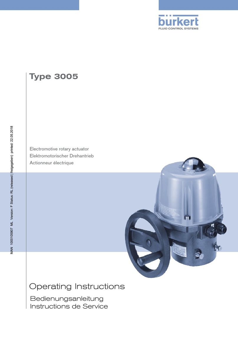
Burkert
Burkert 3005 operating instructions
Flycolor
Flycolor Raptor BLS 4in1-20A user manual
Vega
Vega VEGATOR 111 operating instructions
Siemens
Siemens ECOFAST 3RK1303 S AA Series operating instructions

Production Control Services
Production Control Services PCS 3000 Quick reference guide
Hobbywing Technology
Hobbywing Technology SeaKing-25A user manual
