CLA-VAL 18-4 User manual

Model 18-4
3”- 10”

Product Overview
Model 18-4 RPDA (1991-2003) Utilized the
3084 Toggle Lever Checks and CDHS-24 relief
valve.
Produced in 3”-10” sizes only. Bypass was a ¾”
RP-2 or a Wilkins 975XL.
Replacement hardware parts were discontinued
in 2005. Only Repair kits with rubber parts are
available.

Check Cover Removal
The check covers are secured by bolts and sealed by an o-ring.
3” through 6” sizes remove all but two cover bolts, leaving two bolts 180
degrees apart. Press down on the cover while removing the last two
bolts to prevent the cover from being forcibly ejected by the spring.
8” and 10 sizes, it is suggested that all-thread rod and nuts (jack screws)
be used when removing or replacing the covers. The 8” size uses two
5/8”-11 all-thread approximately 8” long. The 10” size uses two ¾” -10
approximately 8” long. Remove two cover bolts on opposite sides of the
cover, and install all-thread rod. Install and tighten nuts down to cover.
Remove remaining cover bolts. Simultaneously, back the jack screw nuts
off until the spring tension is completely released. Remove the cover.
Check Valve Removal
Remove the two pipe plugs on
each side of the valve body, to
expose the lever arm pin (item
13) and the hinge pin (item 11).
Using a brass rod (smaller in
diameter than the pins), gently
tap out the rear lever arm (item
13) pin first.
CAUTION: Support the lever arm
(item 10) while completely
removing the lever arm pin. Let
the lever arm rest gently in the
bottom of the check valve.

Check Valve Removal
Grasp the yoke (item 7) with
one hand, while removing the
front hinge pin (item 11). Lift out
the toggle- lever clapper
assembly, being careful that the
brass seat is not dented.
NOTE: On 8” and 10” sizes, a
lever arm spacer (item 26) is
installed between the two lever
arms to maintain proper
distance between them, and
prevent binding.
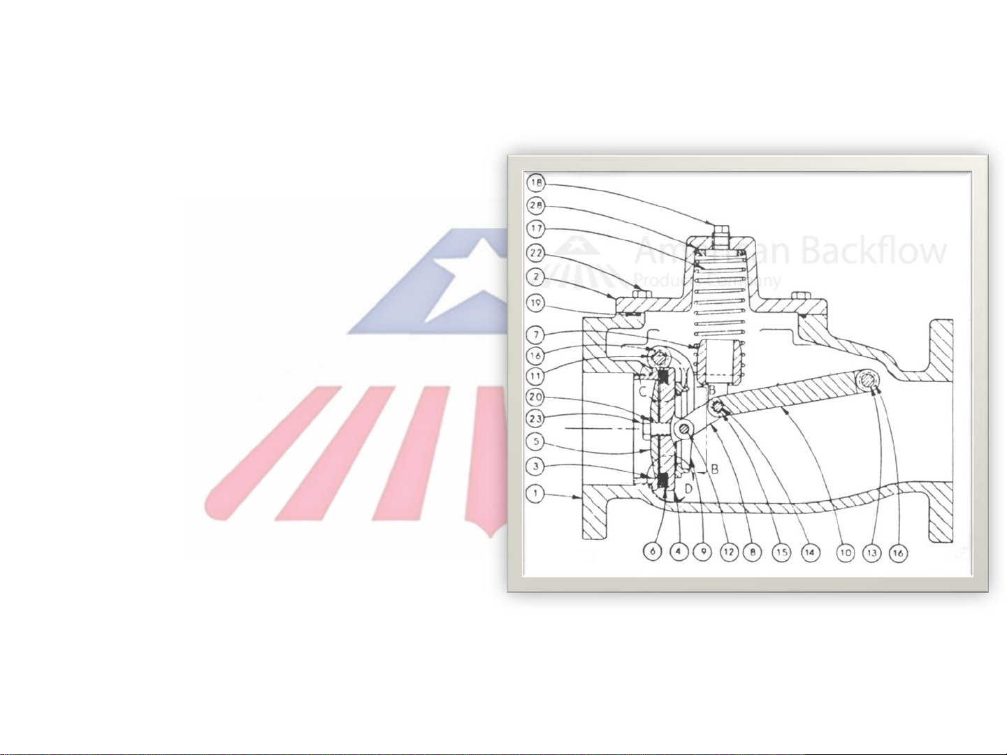
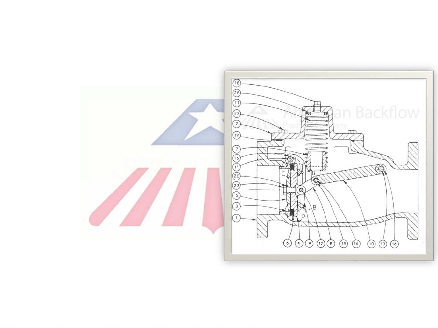
Check Valve Disassembly
2” through 8” sizes remove the
retaining bolt (item 23) from
the center of the disc guide.
10” sizes (only) remove sixteen
retaining screws from the disc
guide (item 5).
The check disc is free once the
guide is separated from the
disc retainer (item 4).
NOTE: An o-ring (item 20) is
installed on the retaining bolts
for sizes 21/2”, 3”, 4”, 6”, and
8”.

Check Seat Service
Check seats are o-ring sealed and pressed into
the body.
Replacement seats are no longer in production.
Very fine nicks on the seating edge can be
restored by slowly working 400 wet or dry
sandpaper back and forth on both sides (top and
inner throat) of the seat.

Check Disc Replacement
When installing a new check disc, fiber spacer
washers between the retainer and guide MAY or
MAY NOT be required.
Fiber spacer washers (item 33) are installed to
ensure the proper “squeeze” on the disc (item 6).
Too many washers will not allow sufficient
squeeze on the disc (not a water tight seal). This
will cause the check valve to fail.
Too few washers between the guide and retainer
can generate TOO MUCH squeeze on the disc,
causing it to bulge around the guide. This will
also cause the check to fail.
Proper squeeze on the disc is achieved when
the disc cannot be rotated and no bulge
appears.
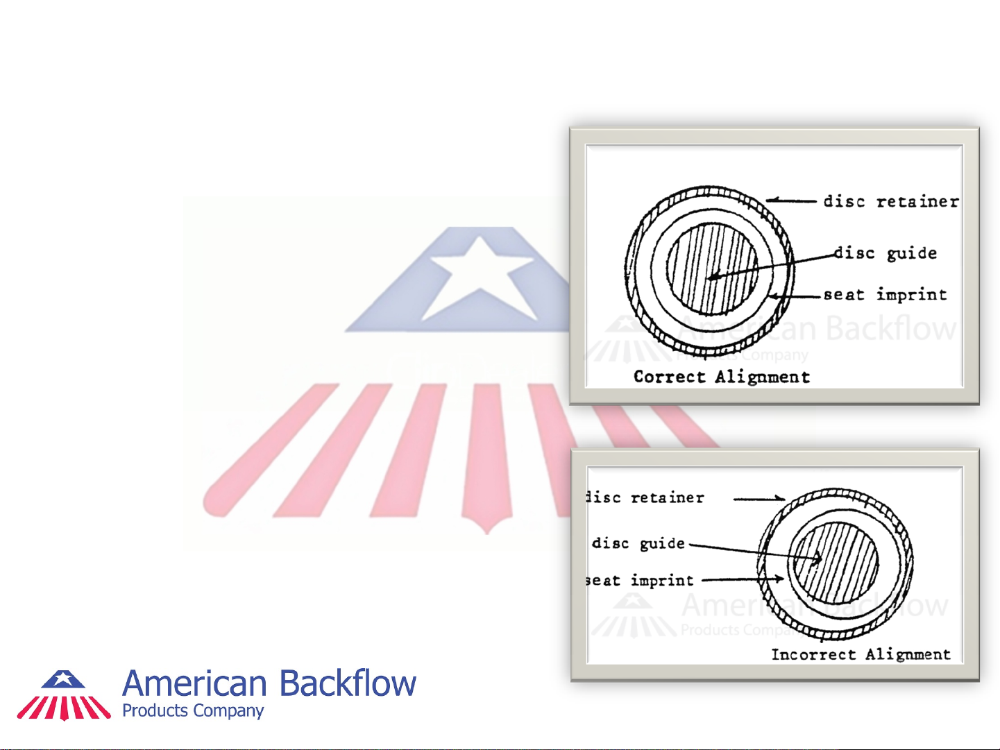
Check Valve Alignment
Re-install clapper assembly. Be
careful not to damage check seat.
Support clapper assembly with
one hand and install hinge pin.
With clapper assembly supported
by hinge pin only, exert pressure
to force disc against the seat, and
leave an imprint of the seat in the
disc.
Remove clapper assembly.
Inspect disc to ascertain that
alignment is correct.
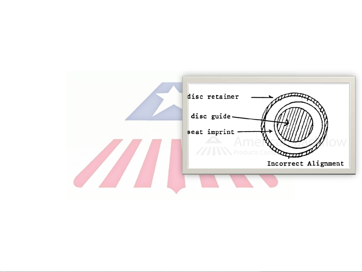
Check Valve Alignment
In the event the seat imprint
indicates an incorrect
alignment, adjust hinge pin
bushing OUT, on the side that
corresponds to the least
distance between the seat
imprint and disc guide.
In this figure, adjust hinge pin
bushing on the RIGHT side
outward.
Alignment is correct if the
seat leaves an imprint on the
disc equi-distant on all sides
of the disc guide.
Check Reassembly Notes
When the two pins that
hold the toggle-lever
(clapper) assembly are
installed, be sure to note
that the yoke (item 7) and
the lever arm pivots
upward freely.
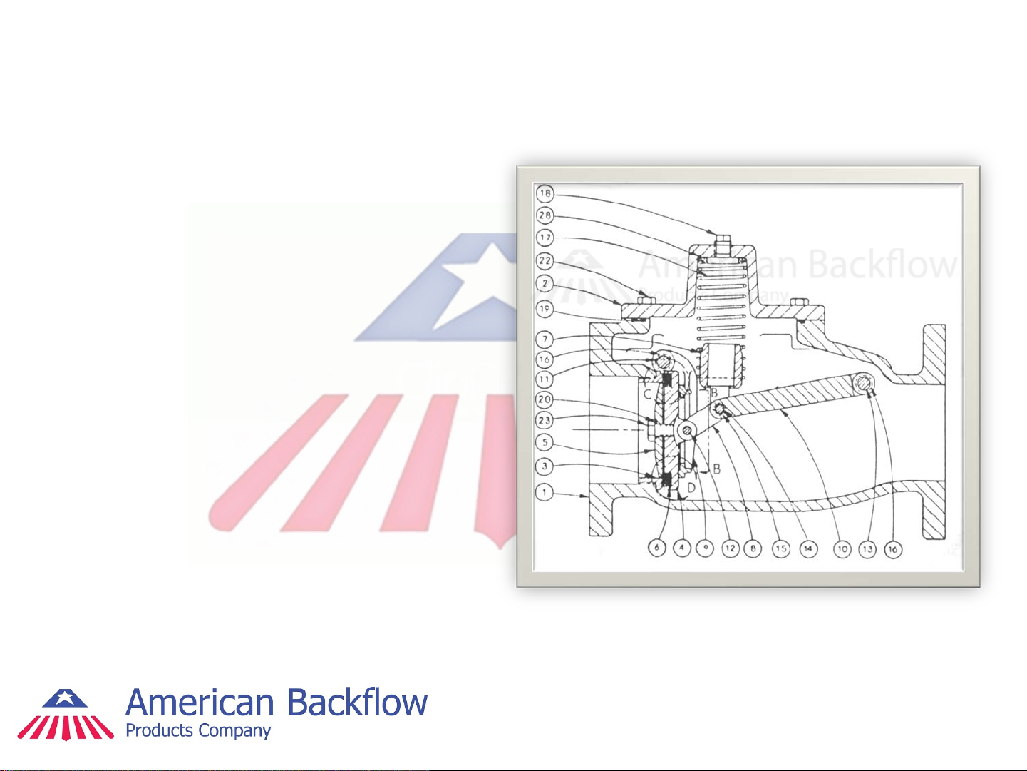
Relief Valve Cover Removal
The CDHS-20/ CDHS-24 RV
has two covers. The bellofram
cover (item 3) and the
intermediate body or “diaphragm
cover” (item 2).
The bellofram cover (item 3) is
located on top of the RV
assembly.
The bellofram cover is secured
by screws and sealed by the
bellofram.
There is no spring load on this
cover.

Relief Valve Cover Removal
The intermediate body (item 2)
is secured by cap screws and
sealed by the diaphragm.
There is a slight spring load on
this cover, so exert pressure
downward on the cover as the
cap screws are removed.
The RV stem assembly is
mounted through the
intermediate body.
The RV spring is free once
cover is removed.

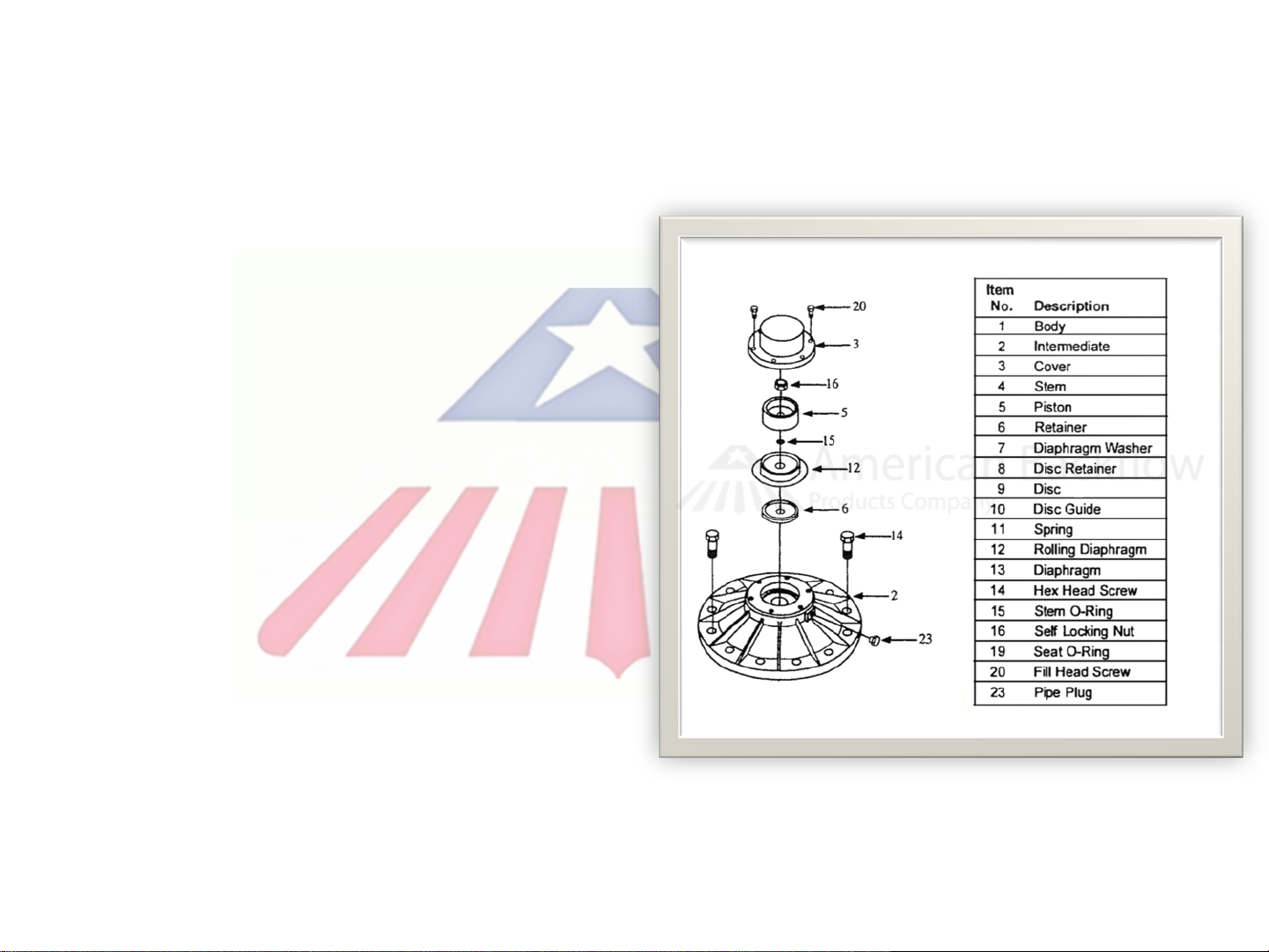
Disassemble RV Stem
The stem is secured by the
upper and lower stem nuts
(item 16).
Remove the upper stem nut
first.
The bellofram, piston and
retainer can now be
removed from the upper
stem.
Remove the stem along
with the diaphragm and disc
from the body.

Disassemble RV Stem
Remove lower stem nut (item
16).
The RV disc (9), disc retainer
(8), and guide (10) are removed
as one assembly.(Simply pry
disc from retainer)
Remove the diaphragm
(item13), the lower stem o-ring
(item 15) and washer (item 7)
from stem.

RV Seat Service
The RV seat is o-ring sealed and threaded into
the main RV body.
Replacement seats are no longer in production.
Very fine nicks on the seating edge can be
restored by slowly working 400 wet or dry
sandpaper back and forth on both sides (top and
inner throat) of the seat.
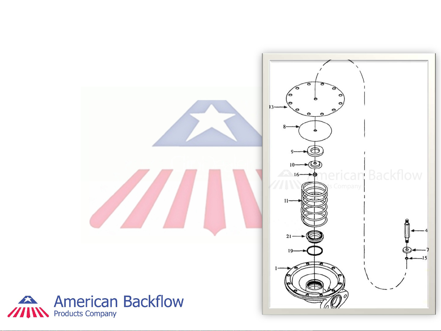
Diaphragm Reassembly
Reassemble the diaphragm (item 13),
lower stem o-ring (item 15) and washer
(item 7) on the lower stem (4).
Reassemble the RV disc, disc retainer,
and guide as one assembly on the lower
stem.
The serrated area of the disc retainer (8)
is positioned against the diaphragm.
Insert the stem (4) with diaphragm and
disc retainer intact, into the intermediate
body.
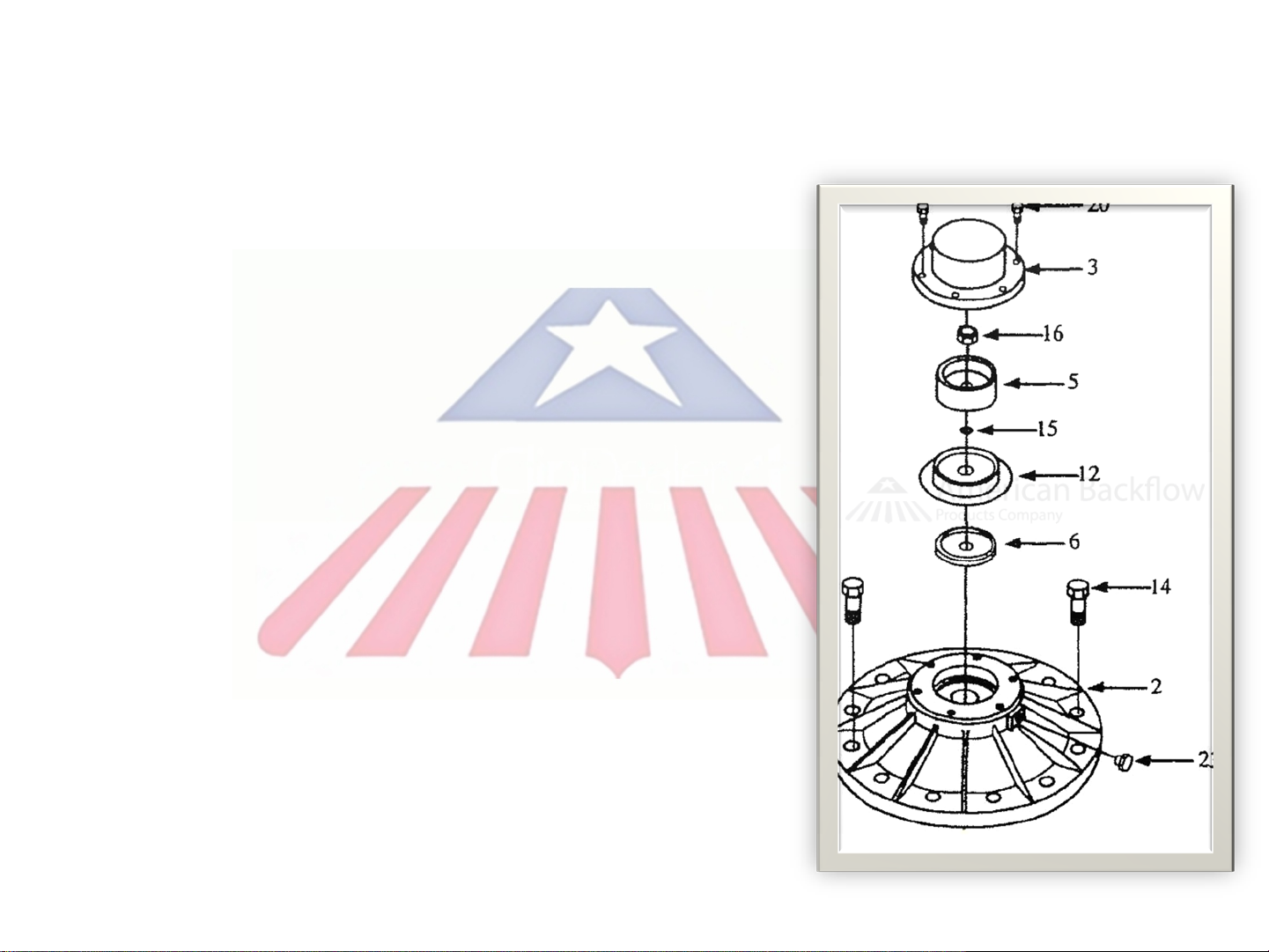
Upper Stem Reassembly
Reassemble the bellofram (12), piston
(5), retainer (6) and stem o-ring (15) on
the upper stem and replace stem nut.
Position the retainer (6) with its outer lip
facing up.
Position the bellofram with the glossy
side against the retainer(6). The fabric
side against the piston(5)
Position the piston (5) with the recess
around the stem hole facing down
toward the o-ring (15).

Intermediate Body Reassembly
Position the RV spring over the seat
in the main body.
Insert cap screws through
intermediate body and diaphragm.
Make sure the sensing passage is
aligned properly.
Press the intermediate body down
on the main body and start cap
screws.
Be sure to evenly cross tighten cap
screws.

Bellofram Reassembly
Carefully push bellofram(12)
“brim” straight down over itself so
that the “brim” is flat and smooth
against the intermediate body.
Make sure the bellofram is not
twisted or wrinkled.
Install cover (3) so that weep
hole faces out away from
backflow.
Do not rotate cover after placing
over the “brim”, this can twist and
tear the bellofram.
Table of contents
Other CLA-VAL Industrial Equipment manuals


Popular Industrial Equipment manuals by other brands


Otec
Otec ECO mini dry operating instructions

Spida Machinery
Spida Machinery Mini 8 Operation & service manual

Showa Denki
Showa Denki CRN Series Operation manual

Bosch
Bosch Rexroth IndraMotion MLC operating instructions

Siemens
Siemens SINUMERIK ONE NCU 1760 Equipment manual

ABB
ABB E-kit installation instructions

Siemens
Siemens 5WG1 125-4AB23 Operating and mounting instructions

CMCO
CMCO TIGRIP THM 120 operating instructions

PCB Piezotronics
PCB Piezotronics 320C34 Installation and operating manual

ABB
ABB HT613266 Operation manual

Yamaha
Yamaha SIGMA-G5SII Service information

Doosan
Doosan 7/124 Operation & maintenance manual