manuals.online logo
Brands
  1. Home
  2. •
  3. Brands
  4. •
  5. Siemens
  6. •
  7. Industrial Equipment
  8. •
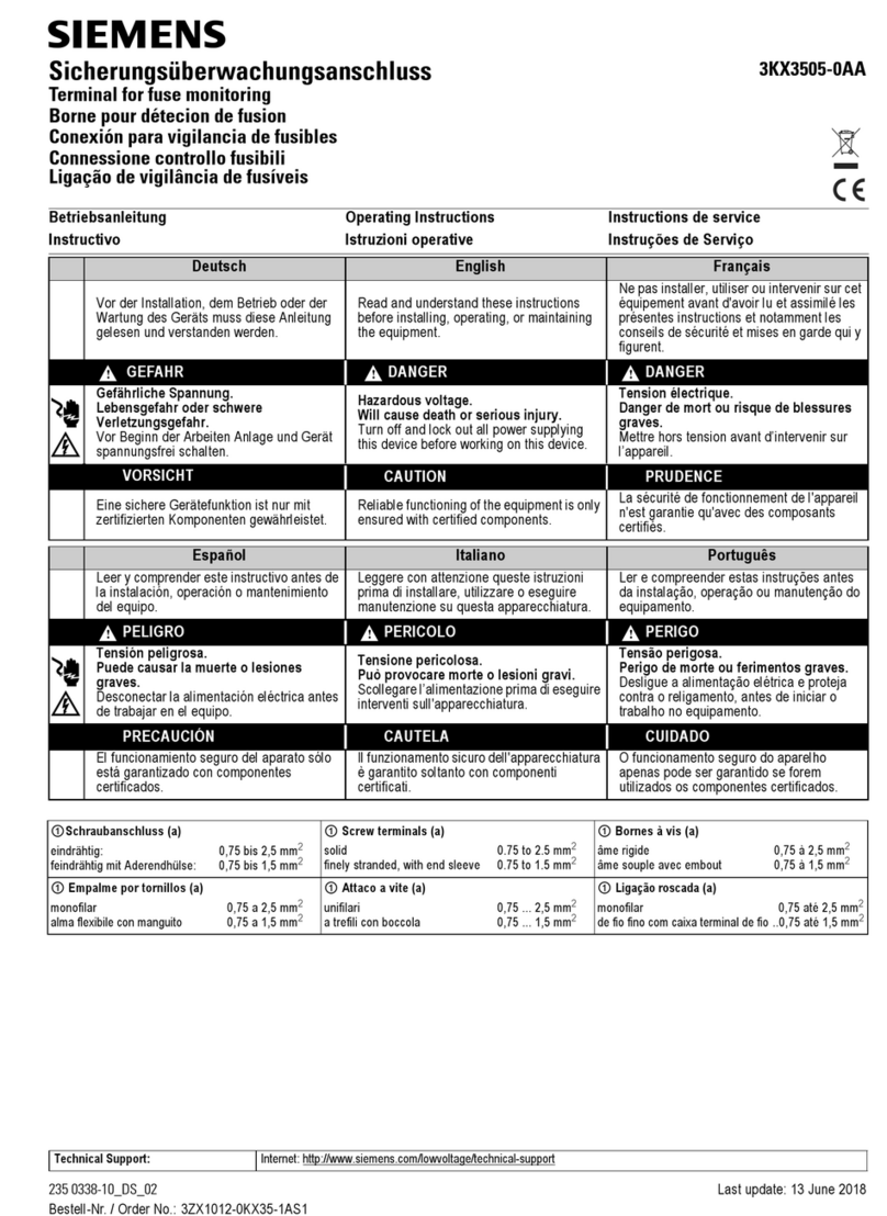
  9. Siemens 5WG1 125-4AB23 Service manual

Siemens 5WG1 125-4AB23 Service manual

D
GB
L1V30356152A DS01 Seite 1 von 4 page 1 of 4
GAMMA instabus
RL 125/23 Dezentrale Spannungsversorgung,
80mA
5WG1 125-4AB23
RL 125/23 Decentralized power supply, 80mA
5WG1 125-4AB23
Bedien- und Montageanleitung
Operating and Mounting Instructions
Stand: Dezember 2014
Issued: December 2014
Bild / Figure 1
Produkt- und Funktionsbeschreibung
Die Dezentrale Spannungsversorgung RL 125/23 erzeugt die für
KNX erforderliche Systemspannung.
Das Gerät wird in einer AP 118 Automationsmodulbox oder in
der AP 641 Raumautomationsbox installiert. Der Busanschluss
erfolgt über eine Busklemme.
Die integrierte Drossel verhindert den Kurzschluss der Datente-
legramme auf der Buslinie. Für jede Buslinie wird mindestens
eine Spannungsversorgung benötigt. Eine zweite Spannungs-
versorgung ist nur erforderlich, wenn die Betriebsspannung an
einem Teilnehmer unter 21 V abfällt. In einer Buslinie sind bis zu
acht Spannungsversorgungen RL 125/23 zulässig.
Hinweis: Wird mindestens eine Spannungsversorgung parallel
an einer Buslinie betrieben, so ist bei Aufleuchten der Überlast-
anzeige an einer oder mehreren Busspannungsversorgungen die
Buskonfiguration so zu ändern, dass keine Überlastanzeige mehr
erfolgt.
Zwischen den Spannungsversorgungen RL 125/23 ist keine Min-
destleitungslänge notwendig. Zusätzlich ist an dieser Buslinie
der Betrieb einer Busspannungsversorgung N125/x2 zulässig,
solange die Summe der Kurzschlußströme aller Busspannungs-
versorgungen einer Buslinie 3A nicht überschreitet.
Werden mehrere Busteilnehmer z.B. in einem Verteiler mit kur-
zen Leitungsdistanzen (z.B. 10 m) oder in einer Raumautomati-
onsbox AP641 eingebaut, soll die Spannungsversorgung
RL 125/23 in der Nähe dieser Busteilnehmer angeordnet wer-
den. Die Entfernung zwischen einem Busgerät und der nächsten
Spannungsversorgung darf max. 350 m sein. Wenn nur die de-
zentrale Spannungsversorgung RL 125/23 verwendet wird, dann
darf die maximale KNX Leitungslänge einer Buslinie 350m bei
einer, 700m bei zwei und 1000m bei drei oder mehr dezentra-
len Spannungsversorgungen RL 125/23 betragen.
Die Dezentrale Spannungsversorgung RL 125/23 hat eine Span-
nungs- und Stromregelung und ist damit kurzschlußfest. Kurze
Netzunterbrechungen überbrückt sie mit mindestens 100 ms
Pufferzeit.
Aus Gründen der Versorgungssicherheit wird empfohlen, für
den Netzanschluss der Spannungsversorgung RL 125/23 einen
eigenen, separat abgesicherten Stromkreis zu verwenden.
Applikationsprogramme
Für die Dezentrale Spannungsversorgung RL 125/23 gibt es kein
Applikationsprogramm.
Weitere Informationen
http://www.siemens.de/gamma-td
Anschlussbeispiel
siehe Bild 1
Product and Application Description
The decentralized power supply unit RL 125/23 provides the sys-
tem power necessary for KNX.
The device is installed in an AP118 Control Module Box or an
AP 641 Room Control Box. The bus is connected via a bus termi-
nal block.
The integrated choke prevents the data telegrams from short-
circuiting on the bus line.
For each bus line, at least one decentralized power supply unit
RL 125/23 is needed. A second unit is not required unless the
supply voltage at a bus device is less than 21 V. Up to eight de-
centralized power supply units RL125/23 may be attached in
parallel to a single bus line.
Note: If two or more power supply units are operated in parallel
on one bus line and if the overload LED is lit on one or several
power supplies, then the bus configuration has to be changed
until the overload display disappears on all units.
A minimum cable length is not required between the decentral-
ized power supplies RL 125/23. Operation of a power supply unit
N125/x2 in parallel to the decentralized power supplies is per-
mitted on the same bus line as long as the sum of all short cir-
cuit currents of all power supplies does not exceed 3A.
When several bus devices are installed in short bus cable dis-
tance (e.g. 10m), e.g. in distribution boards, or in a room con-
trol box AP 641, the power supply units shall be arranged near
these bus devices. The distance along the bus wire between any
bus device and the closest power supply unit must not exceed
350 m. If only the decentralized power supply RL 125/23 is used,
then the maximum KNX cable length in a bus line is 350m for
one, 700m for two, and 1000m for 3 or more decentralized
power supplies RL 125/23.
The decentralized power supply unit RL125/23 has a voltage
and current regulation and is therefore short-circuit proof. Short
power failures can be bridged with a backup interval of at least
100 ms.
To ensure an uninterrupted power supply a separate circuit with
safety separation should be used for the mains power supply
circuit of all power supply units.
Application Program
No application program is required for the Decentralized Power
Supply RL 125/23
Additional Information
http://www.siemens.com/gamma-td
Example of Operation
see figure 1
D
GB
L1V30356152A DS01 Seite 2 von 4 page 2 of 4
Bild / Figure 2
Technische Daten
Eingangsspannung
·Bemessungsspannungen: AC 120-230 V, 50 ... 60 Hz
DC 220V
Bemessungsleistungsaufnahme
ca. 10 VA
Ausgangsspannung
·Bemessungsspannung DC 29 V
·Schutzkleinspannung (SELV)
·zulässiger Bereich DC 28 ... 30 V
Ausgangsstrom
·Bemessungsstrom 80 mA
·Kurzschlußstrom: begrenzt auf 0,2 A
Pufferzeit
bei Ausfall der Eingangsspannung ≥100 ms
bei Bemessungsstrom
Anschlüsse
·Buslinie: Busstifte zum Aufstecken der Busklemme schrauben-
los, 0,6 ... 0,8 mm Ø eindrähtig,
Abisolierlänge 5mm
·Netzstromkreis: schraubenlose Klemmen
0,5 ... 2,5mm² eindrähtig, feindrähtig oder mehrdrähtig,
unbehandelt, Abisolierlänge 9 ... 10mm
Mechanische Daten
·Gehäuse: Kunststoff
·Abmessungen (L x B x T): 86,5 x 47,8 x 36,2 mm
·Gewicht: ca. 78 g
Elektrische Sicherheit
·Schutzart (nach EN 60529): IP 20
Umweltbedingungen
·Umgebungstemperatur im Betrieb: - 5 ... + 45 °C
·Lagertemperatur: - 25 ... + 70 °C
·rel. Feuchte (nicht kondensierend): 5 % bis 93 %
Lage- und Funktion der Anzeige- und Bedienelemente
siehe Bild 2
A1 LED zur Anzeige
- Normalmodus (LED aus),
- KNX Buskurzschluß oder Geräteüberlast (LED ein)
A3 Busstifte des Moduls zum Aufstecken der Busklemme für
eindrähtige Leiter mit 0,6 ... 0,8mm Æ
A4 Typenschild
A5 Anschlussklemme L
A6 Anschlussklemme N
A7 Warnhinweis
Installationshinweise
·Das Gerät ist zum Einbau in eine AP 118 Automationsmodul-
box oder in eine AP 641 Raumautomationsbox bestimmt.
ΥGEFAHR
·Das Gerät darf nur von einer zugelassenen Elektrofachkraft
installiert und in Betrieb genommen werden.
·Beim Anschluss des Gerätes ist darauf zu achten, dass das Ge-
rät freigeschaltet werden kann.
·GEFÄHRLICHE SPANNUNG NACH AB-SCHALTEN DER VERSOR-
GUNG MÖGLICH! Elektronik des Gerätes nicht berühren!
Bei einem defekten Gerät kann auch nach Freischaltung für
bis zu 4 Stunden das RISIKO EINES ELEKTRISCHEN SCHLAGES
bestehen!
·Das Gerät darf nicht geöffnet werden.
·Bei der Planung und Errichtung von elektrischen Anlagen sind
die einschlägigen Richtlinien, Vorschriften und Bestimmun-
gen des jeweiligen Landes zu beachten.
·Beim Durchschleifen des L-Leiters ist zu beachten, dass der
maximale zulässige Klemmenstrom von 16A nicht überschrit-
ten werden darf!
Technical Data
Input voltage
·rated voltage: AC 120-230 V, 50...60Hz
DC 220V
Rated power intake
approx. 10 VA
Output voltage
·rated voltage: DC 29 V
·safety extra low voltage (SELV)
·permissible range: DC 28 ... 30 V
Output current
·rated current 80 mA
·short-circuit current: limited to 0.2 A
Backup interval
on input voltage failure: ≥100 ms at rated current
Connections
·Bus line : Bus connection pins for connection of the screwless
bus terminal block (red-black) 0.6…0.8 mm Ø single core,
strip insulation 5mm
·Mains circuit: screwless terminals
0.5 ... 2.5mm² single-core, stranded or multi-core,
untreated, strip insulation 9 ... 10mm
Physical specifications
·housing: plastic
·dimensions (L x W x D): 86.5 x 47.8 x 36.2 mm
·weight: approx 62 g
Electrical safety
·Protection type (in accordance with EN 60529): IP 20
Environmental conditions
·Ambient operating temperature: - 5 ... + 45 °C
·Storage temperature: - 25 ... + 70 °C
·Relative humidity (not condensing): 5 % to 93 %
Location / Function of the Display and Operating Elements
see figure 2
A1 LED for indicating
- normal operating mode (LED off),
- a shorted-out bus line or device over-load (LED on)
A3 Bus connection pins of the module for connection of the
bus terminal block for single core conductors with
0.6...0.8 mm Ø
A4 Type label
A5 Terminal L
A6 Terminal N
A7 Warning label
Installation notes
·The device is intended for installation in an AP 118 Control
Module Box or an AP 641 Room Control Box.
ΥDANGER
·The device must be mounted and commissioned by an au-
thorized electrician.
·A safety disconnection of the device must be possible.
·HAZARDOUS VOLTAGE POSSIBLE AFTER DISCONNECTING
MAINS! Do not touch electronics of the device!
If the device is defective, then even after safety disconnection
of the device a RISK OF ELECTRIC SHOCK can exist for up to 4
hours after disconnection!
·The device must not be opened.
·For planning and construction of electric installations, the
relevant guidelines, regulations and standards of the respec-
tive country are to be considered.
·When looping through the L-conductor, take care that the
maximum permissible terminal load current of 16A is not ex-
ceeded!
D
GB
L1V30356152A DS01 Seite 3 von 4 page 3 of 4
Bild / Figure 3-c
Bild / Figure 3-d
Montage und Verdrahtung
B2 RL-Modul
B3 Typenschild
B4 Steckplatz für RS-/RL-Modul in AP 118 Automationsmodul-
box oder AP 641 Raumautomationsbox
B9 LED zur Anzeige
- Normalmodus (LED aus),
- KNX Buskurzschluß oder Geräteüberlast (LED an)
B10 Busstifte des Moduls zum Aufstecken der zum Steckplatz
gehörenden Busklemme der internen Busleitung
B11 Steckplatz für Busklemme
B12 Busklemme für eindrähtige Leiter mit 0,6 … 0,8 mm Æ
B13 Einhängepunkt für Montagehaken des RL-Moduls
B14 Anschlussklemmen
B15 Warnhinweis
·Montage eines RL-Moduls (Bild 3-c):
- Entfernen Sie den Deckel der AP 118 Automationsmodulbox
bzw. der AP 641 Raumautomationsbox.
- AP 641: Entfernen Sie die SELV-Abdeckung
- Hängen Sie das RL-Modul (B2) in die Einhängung (B13) des
Steckplatzes (B4). Die Anschlussklemmen (B14) zeigen weg
von dem Busklemmensteckplatz (B11). Das Typenschild (B3) ist
oben.
- Klappen Sie das RL-Modul (B2) nach unten bis es im Steckplatz
(B4) einrastet.
- Stecken Sie die Busklemme (B12) des Steckplatzes (B4) auf die
Busstifte (B10) des RL-Moduls (B2).
- AP 641: Setzen Sie die SELV-Abdeckung wieder ein.
- Montieren Sie den Deckel bzw. die SELV-Abdeckung wieder.
·Demontage eines RL-Moduls (Bild 3-d):
- Entfernen Sie den Deckel der AP 118 Automationsmodulbox
bzw. der AP 641 Raumautomationsbox.
- AP 641: Entfernen Sie die SELV-Abdeckung.
- Lösen Sie die Leitungen aus den Anschlussklemmen (B14).
- Ziehen Sie die Busklemme (B12) ab.
- Lösen Sie das RL-Modul (B2), indem Sie das Modul auf der Bus-
klemmenseite mit einem Schlitzschraubendreher aus der
Verschnappung lösen.
ΥWARNUNG
GEFÄHRLICHE SPANNUNG NACH ABSCHALTEN DER VERSOR-
GUNG MÖGLICH! Elektronik des Gerätes nicht berühren!
Bei einem defekten Gerät kann auch nach Freischaltung für bis
zu 4 Stunden das RISIKO EINES ELEKTRISCHEN SCHLAGES be-
stehen!
- Klappen Sie das RL-Modul (B2) hoch, ziehen es nach unten aus
der Einhängung (B13) und entfernen es aus dem Steckplatz
(B4).
- AP 641: Setzen Sie die SELV-Abdeckung wieder ein.
- Montieren Sie den Deckel wieder.
Mounting and Connecting
B2 RL module
B3 Type label
B4 Mounting location for RS / RL module in AP 118 Control
Module Box or AP 641 Room Control Box
B9 LED for indicating
- normal operating mode (LED off),
- reset mode (LED on),
- a shorted-out bus line or
- device over-load
B10 Bus connection pins of the module for connection of the
associated bus terminal block of the internal bus wire
B11 Insertion point for bus terminal block
B12 Bus terminal block for single core conductors with 0.6 …
0.8 mm Æ
B13 Hinge joint for mounting hinge of the RL module
B14 Terminals
B15 Warning label
·Mounting of an RL module (Figure 3-c):
- Remove the lid of the AP 118 Control Module Box respectively
of the AP 641 Raumautomationsbox.
- AP 641: Remove the SELV (Class 2) cover
- Insert the RL module (B2) into the hinge (B13) of the mounting
location (B4). The terminals (B14) point away from the inser-
tion point for the bus terminal (B11). The type label (B3) is on
top.
- Swivel the RL module (B2) down until it audibly snaps into the
mounting location (B4).
- Insert the bus terminal (B12) of the mounting location (B4) on-
to the bus connection pins (B10) of the RL module (B2).
- AP 641: Mount the SELV (class 2) cover again.
- Mount the lid again.
·Dismounting an RL module (Bild 3-d):
- Remove the lid of the AP 118 Control Module Box respectively
of the AP 641 room control box.
- AP 641: Remove the SELV (Class 2) cover.
- Remove the wiring from the terminals (B14).
- Remove the bus terminal (B12).
- To remove the RL module (B2), insert a screw driver between
the module and the mounting location on the bus terminal
side and push it up to release it from the snap-in hooks.
ΥWARNING
HAZARDOUS VOLTAGE POSSIBLE AFTER DISCONNECTING
MAINS! Do not touch electronics of the device!
If the device is defective, then even after safety disconnection
of the device a RISK OF ELECTRIC SHOCK can exist for up to 4
hours after disconnection!
- Swivel the RL module (B2) up, pull it down out of the hinge
(B13) and remove it from the mounting location (B4).
- AP 641: Mount the SELV (class 2) cover again.
- Mount the lid again.
B14
B15 B9
B15
B15
B15
D
GB
L1V30356152A DS01 Seite 4 von 4 page 4 of 4
C2
C2.2 C2.1
C2.3
Bild / Figure 4
D2
D2.4
5 mm
D2
D2.4
25...35 mm
D1
Bild / Figure 5
Bild / Figure 6
Verdrahtung
Busklemme abziehen/aufstecken (Bild 4)
Die Busklemme (C2) besteht aus zwei Teilen (C2.1, C2.2) mit je
vier Klemmkontakten. Es ist darauf zu achten, dass die beiden
Prüfbuchsen (C2.3) weder mit dem Busleiter (versehentlicher
Steckversuch) noch mit dem Schraubendreher (beim Versuch
die Busklemme zu entfernen) beschädigt werden.
Busklemme abziehen (Bild 4)
- Den Schraubendreher vorsichtig in den Drahteinführungs-
schlitz des schwarzen Teils der Busklemme (C2,2) einführen
und
- die Busklemme (C2) aus dem Modul herausziehen.
Hinweis
Busklemme nicht von unten heraushebeln! Kurzschlussgefahr!
Busklemme aufstecken (Bild 4)
- Die Busklemme (C2) in die Führungsnut des Moduls stecken
und
- die Busklemme (C2) bis zum Anschlag nach unten drücken.
Anschließen der Busleitung (Bild 5)
- Die Busklemme (D2) ist für eindrähtige Leiter mit
0,6 ... 0,8mm Ø geeignet.
- Den Leiter (D1) ca. 5mm abisolieren und in Klemme (D2)
stecken (rot = +, grau = -)
Abklemmen der Busleitung (Bild 5)
- Die Busklemme (D2) abziehen und den Leiter (D2.4) der Bus-
leitung, bei gleichzeitigem Hin- und Herdrehen, herauszie-
hen.
Netz-/Laststromkreis anschließen und abklemmen: siehe Bild 6
Leiter anschließen
- Die Anschlüsse für die Leiter bestehen aus schraubenlosen
Steckklemmen (E1).
- Die Leiter (E2) ca. 9 ... 10mm abisolieren und in die
Klemmen (E1) stecken.
- Die Klemmen sind für das Einstecken zweier Leiter ausgelegt,
so dass ein Durchschleifen über die Klemmen möglich ist.
Hinweis:
Die Klemmen dürfen maximal mit 16A belastet werden.
Leiter abklemmen
Mit dem Schraubendreher auf die Verriegelung der Klemme (F1)
drücken und den (die) Leiter (F2) aus der Klemme (F1) ziehen.
Wiring
Slipping off/on bus connection blocks (figure 4)
The bus terminal block (C2) consists of two components (C2.1
and C2.2) with four terminal contacts each. Take care not to
damage the two test sockets (C2.3) by accidentally connecting
them to the bus cable or with the screw driver (e.g. when at-
tempting to unplug the bus terminal block).
Slipping off bus connection blocks (figure 4)
- Carefully put the screw driver to the wire insertion slit of the
bus terminal block’s grey component (C2.2) and
- pull the bus terminal block (C2) from the module.
Note
Don’t try to remove the bus connection block from the bottom
side. There is a risk of shorting-out the device!
Slipping on bus connection blocks (figure 4)
- Slip the bus terminal block (C2) onto the guide slot of the
module and
- press the bus terminal block (C2) down to the stop.
Connecting bus cables (figure 5)
- The bus terminal block (D2) can be used with single core
conductors Ø 0.6…0.8 mm.
- Remove approx. 5 mm of insulation from the conductor (D1)
and plug it into the bus terminal block (D2)
(red = +, grey = -)
Disconnecting bus cables (figure 5)
- Unplug the bus terminal block (D2) and remove the bus cable
conductor (D2.4) while simultaneously wiggling it.
Connecting/disconnecting mains and load circuit: see figure 6
Connect wires
- The load circuits are connected via screwless plug-in terminals
(E1).
- Remove approx. 9…10 mm of insulation from the wire (E 1.1)
and plug it into the terminal (E1).
- The terminals are designed for connection of two wires allow-
ing to loop through the terminal block.
Note:
The maximum permissible terminal load current is 16A.
Remove wires
Press the terminal interlocking of the terminal (F1) with a
screw-driver and remove the wire (F2) from the terminal (F1).
Technical Support
'+49 (911) 895-7222
7+49 (911) 895-7223
*support.automation@siemens.com
www.siemens.de/automation/support-request
Allgemeine Hinweise
·Die Bedienungsanleitung ist dem Kunden auszuhändigen.
·Ein defektes Gerät ist mit einem Rücklieferschein der zustän-
digen Vertriebsniederlassung zurückzusenden.
·Bei zusätzlichen Fragen zum Produkt wenden Sie sich bitte an
unseren Technical Support.
General Notes
·The operating instructions must be handed over to the client.
·A faulty device shall be returned with a Return Good Note for
Service provided by the appropriate Siemens sales office.
·If you have further questions concerning the product please
contact our technical support.

Other Siemens Industrial Equipment manuals

Siemens MAMMOMAT Novation Technical specifications

Siemens

Siemens MAMMOMAT Novation Technical specifications

Siemens 3KY2 204-0A User manual

Siemens

Siemens 3KY2 204-0A User manual

Siemens 3RS17 Series User manual

Siemens

Siemens 3RS17 Series User manual

Siemens 3VA9670-0LF20 User manual

Siemens

Siemens 3VA9670-0LF20 User manual

Siemens 3VA9 7-OPK1 Series User manual

Siemens

Siemens 3VA9 7-OPK1 Series User manual

Siemens SIVACON 8PS LD Series User manual

Siemens

Siemens SIVACON 8PS LD Series User manual

Siemens SIDOOR ATD400T User guide

Siemens

Siemens SIDOOR ATD400T User guide

Siemens 3VA9131-0WF 0 Series User manual

Siemens

Siemens 3VA9131-0WF 0 Series User manual

Siemens SIMATIC S7-1200 Easy Book User manual

Siemens

Siemens SIMATIC S7-1200 Easy Book User manual

Siemens 3VF9821-1 40 Series User manual

Siemens

Siemens 3VF9821-1 40 Series User manual

Siemens 3VT9500-8CH30 User manual

Siemens

Siemens 3VT9500-8CH30 User manual

Siemens 8MF1 Series User manual

Siemens

Siemens 8MF1 Series User manual

Siemens SIMATIC ET 200SP User manual

Siemens

Siemens SIMATIC ET 200SP User manual

Siemens SIRIUS ACT 3SU19 User manual

Siemens

Siemens SIRIUS ACT 3SU19 User manual

Siemens SIRIUS 3RA131.-8XB3 User manual

Siemens

Siemens SIRIUS 3RA131.-8XB3 User manual

Siemens RHVE64X User manual

Siemens

Siemens RHVE64X User manual

Siemens SIMATIC ET 200eco PN Technical Document

Siemens

Siemens SIMATIC ET 200eco PN Technical Document

Siemens SIVACON User manual

Siemens

Siemens SIVACON User manual

Siemens SIMATIC S7-200 User manual

Siemens

Siemens SIMATIC S7-200 User manual

Siemens 3WN6 User manual

Siemens

Siemens 3WN6 User manual

Siemens SIMATIC S7-155R/H Technical Document

Siemens

Siemens SIMATIC S7-155R/H Technical Document

Siemens SIRIUS 3RK1400 User manual

Siemens

Siemens SIRIUS 3RK1400 User manual

Siemens SIRIUS 3RA231-8X 3-1 Series User manual

Siemens

Siemens SIRIUS 3RA231-8X 3-1 Series User manual

Siemens SINUMERIK MPP 1500D Technical Document

Siemens

Siemens SINUMERIK MPP 1500D Technical Document

Popular Industrial Equipment manuals by other brands

Transfluid KR Series Installation and Maintenance

Transfluid

Transfluid KR Series Installation and Maintenance

Tecnosystemi Toolsplit HTS user manual

Tecnosystemi

Tecnosystemi Toolsplit HTS user manual

SEW-Eurodrive CM3C63-100 operating instructions

SEW-Eurodrive

SEW-Eurodrive CM3C63-100 operating instructions

HEIDENHAIN LS 3x8 Replacing Instructions

HEIDENHAIN

HEIDENHAIN LS 3x8 Replacing Instructions

Kobelt 7085-S owner's manual

Kobelt

Kobelt 7085-S owner's manual

TLV QuickTrap FP32 instruction manual

TLV

TLV QuickTrap FP32 instruction manual

Bastian Solutions Shoe Sorter Installation and maintenance manual

Bastian Solutions

Bastian Solutions Shoe Sorter Installation and maintenance manual

Zimmer HRC-04 Series Installation and operating instructions

Zimmer

Zimmer HRC-04 Series Installation and operating instructions

GPD Global CF-9 Documentation

GPD Global

GPD Global CF-9 Documentation

WIKA TR12 Series operating instructions

WIKA

WIKA TR12 Series operating instructions

Kalamazoo 2SK7 instruction manual

Kalamazoo

Kalamazoo 2SK7 instruction manual

Conmet Conventional Service manual

Conmet

Conmet Conventional Service manual

Omron sysmac FH Series Hardware setup manual

Omron

Omron sysmac FH Series Hardware setup manual

Walther prazision 91489 Working Instruction

Walther prazision

Walther prazision 91489 Working Instruction

Hallowell EMC Vetronic Tafonius operating manual

Hallowell EMC

Hallowell EMC Vetronic Tafonius operating manual

Baltimore Aircoil Company BCP2D Installation, Operating, Maintenance

Baltimore Aircoil Company

Baltimore Aircoil Company BCP2D Installation, Operating, Maintenance

Lissmac SBM-M 1000 B2 operating manual

Lissmac

Lissmac SBM-M 1000 B2 operating manual

Grizzly G0707 owner's manual

Grizzly

Grizzly G0707 owner's manual

manuals.online logo
manuals.online logoBrands
  • About & Mission
  • Contact us
  • Privacy Policy
  • Terms and Conditions

Copyright 2025 Manuals.Online. All Rights Reserved.