Claas LEXION 770 2016 Installation guide
Information and Basic Field
Settings for LEXION version 14
Information and Basic
Field Settings for LEXION 2016

1

2
Contents
Pages
3
4
5 - 6
7 - 9
10- 11
12 - 21
22- 24
28 -31
30
32- 34
35
36
38- 40
41- 42
44
45 - 46
Title
Introduction
Safety
Overview
Cab and controls
Steering column
CEBIS
CRUISE PILOT
CEBIS mobile/CEMOS
Threshing
Separation
Cleaning
Straw and Chaff Management
Settings aid
Maintenance
Frequent Questions
Wet harvest recomendations

3
Introduction
This quick reference guide has been produced to aid operators with
familiarisation and settings of CLAAS LEXION combine harvesters.
CLAAS combines are designed for output and efficiency but this can only be
achieved with correct operation and maintenance of the machine.
This guide is not designed to replace the Operators Manual but merely as a
reference document. More in depth information is available in the Operators
Manual.
ALWAYS READ THE OPERATORS MANUAL BEFORE OPERATING YOUR COMBINE.
Down time costs output
To get the most from the machine, the wheels/tracks must be turning. In order to
keep downtime to a minimum, it’s vital that routine maintenance is not
neglected. As well as servicing the machine according to the operator’s manual, a
good check of the machine is essential.
It is false economy to put off the replacement of worn parts until they break. For
example, a cracked knife section will take 5 minutes to change before starting
work, but usually a minimum of 10 minutes output will be lost, once work has
begun.
Abbreviations
Throughout this guide the following abbreviations are used:
‘LHS’ and ‘RHS’ refer to the Left Hand Side and Right Hand Side of the machine
respectively, taken from the rear of the machine facing in the direction of travel.
APS –Accelerated Pre-Separation, refers to the accelerator drum in front of the
main drum.

4
Safety
Safety is of the utmost importance whilst you are operating and maintaining
your combine harvester. Make sure that all of the risks are assessed to reduce
the likelihood of an accident.
Make sure you are familiar with the controls and operation of the machine and
have read the operators manual.
The combine harvester has many moving parts, guards are designed to keep you
safe, please ensure that all guards are kept in place and in good condition when
operating the machine.
When doing any maintenance work or making adjustments outside of the
machine make sure that the engine is switched off and the battery isolator key is
removed.
If you need to go underneath the front elevator/ cutterbar to make adjustments/
clean concaves, preparation pan, etc. Make sure that the cutterbar lift cylinder
lock is in place.
Some of the maintenance has to be carried out at height, please asses the risk
that this poses and ensure that the task is carried out safely.
When operating the machine be aware of the presence of people particularly in
farmyards, always get someone to help you when reversing in confined areas.
Be aware of the size of your machine, particularly the height, you may be at risk
from contact with overhead power lines and overhead obstructions particularly
but not exclusively when the grain tank lids are up and if extra aerials have been
fitted to your machine.
For more in-depth safety information please consult your operators manual.
Other information is available on the HSE website: www.hse.gov.uk
Always read the Operators Manual before using any new machine.

5
Overview Rotors
1 - Cutterbar
2 - Crop divider
3 - Crop lifter
4 - Reel
5 - Table auger
6 - Feed rake conveyor
7 - Stone trap
8 - APS Drum
9 - APS concave
10 - Threshing drum
11 - Main concave
12 - Impeller
15 - Return floor
16 - Preparation floor
17 - Upper sieve
18 - Lower sieve
19 - Clean grain cross auger
20 - Returns cross auger
21 - Cleaning fan
22 - Air duct
23 –Chaff blower
24 - Straw chopper
26 - Returns elevator
27 - Clean grain elevator
28 - Grain tank
29 - Bubble-up auger
30 - Unloading auger
31 - Gearbox
32 - Rotor concave
33 - Rotor
34 –Power spreader
Overview: Rotary
6
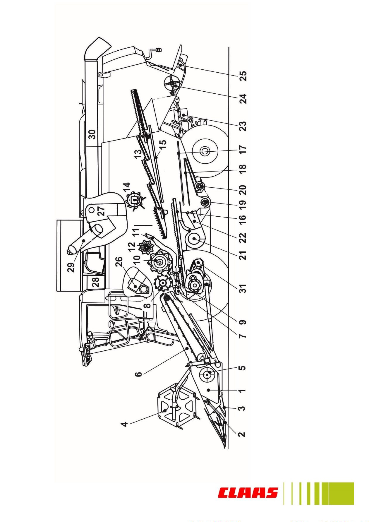
Overview Walkers
1 - Cutterbar
2 - Crop divider
3 - Crop lifter
4 - Reel
5 - Table auger
6 - Feed rake conveyor
7 - Stone trap
8 - APS Drum
9 - APS concave
10 - Threshing drum
11 - Main concave
12 - Impeller
15 - Return floor
16 - Preparation floor
17 - Upper sieve
18 - Lower sieve
19 - Clean grain cross auger
20 - Returns cross auger
21 - Cleaning fan
22 - Air duct
23 - Radial spreader
24 - Straw chopper
26 - Returns elevator
27 - Clean grain elevator
28 - Grain tank
29 - Bubble-up auger
30 - Unloading auger
31 - Gearbox
32 - Rotor concave
33 - Rotor
34 - Chaff spreader
Overview: Straw Walker
7
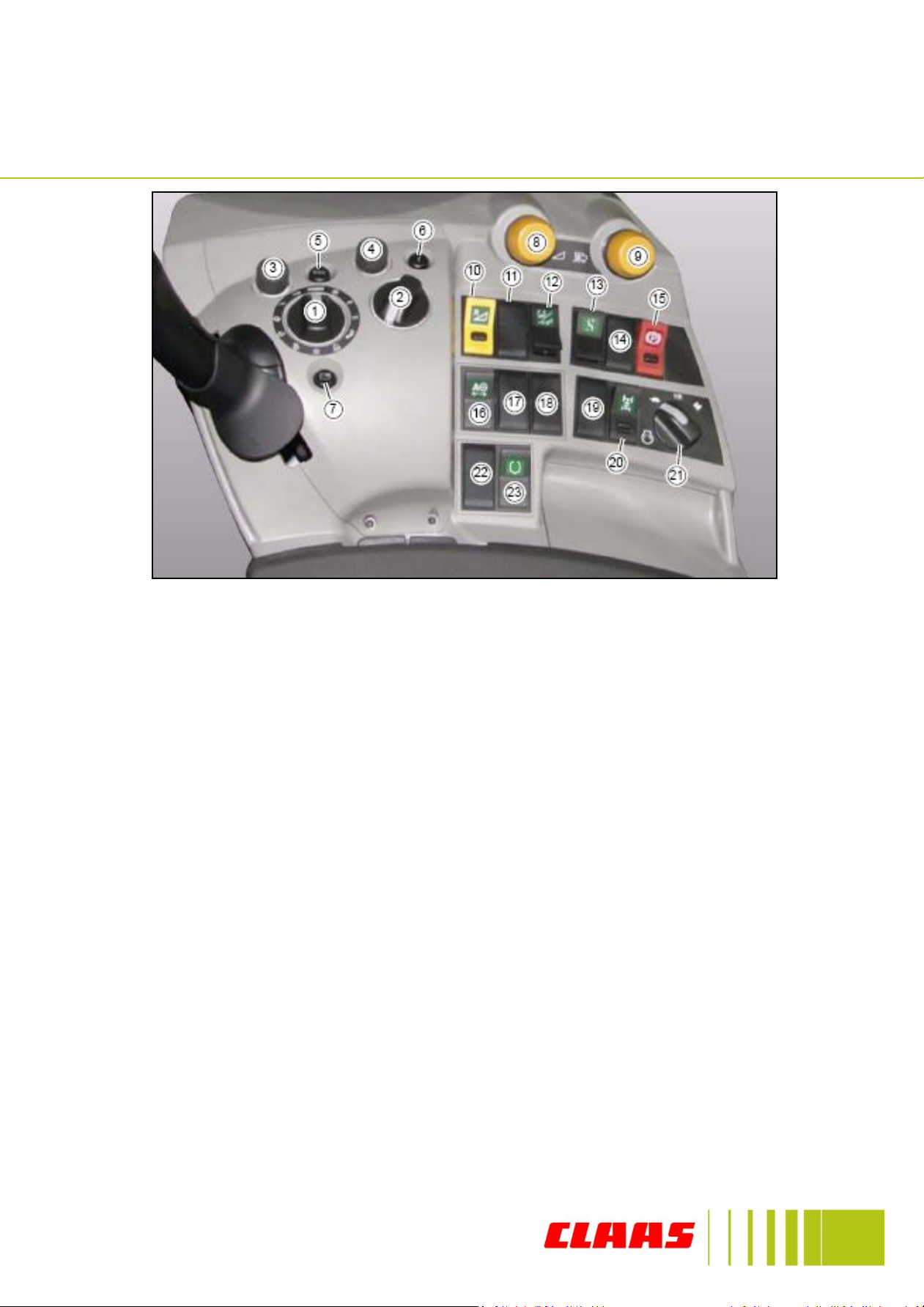
Right Hand Console
1. CEBIS rotary switch
2. HOTKEY rotary switch
3. Main menu rotary switch
4. Value select rotary switch
5. ESC button
6. Information button
7. Quick access button
8. Front Attachment Engagement
9. Threshing Engagement
10. Front Attachment reverser
11. Left hand rape knife switch
12. Front attachment cross levelling
/ VARIO length adjustment/Hotkey
13. Gear Selection switch
14. Not Used
15. Park Brake
16. LASER PILOT left & right
selector switch
17. Not Used
18. Not Used
19. Not Used
20. POWER TRAC switch
21. Engine speed switch
22. Not Used
23. Grain tank extension
8
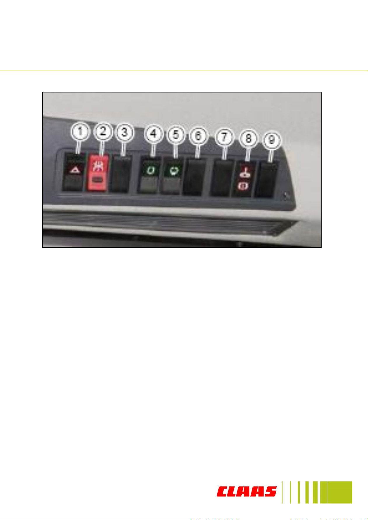
Roof console
1. Hazard warning lights
2. Road travel switch
3. Not used
4. Not used
5. Front attachment folding
6. Not used
7. Not used
8. Track tension/Montana brake warning
9. Emergency steering indicator
9
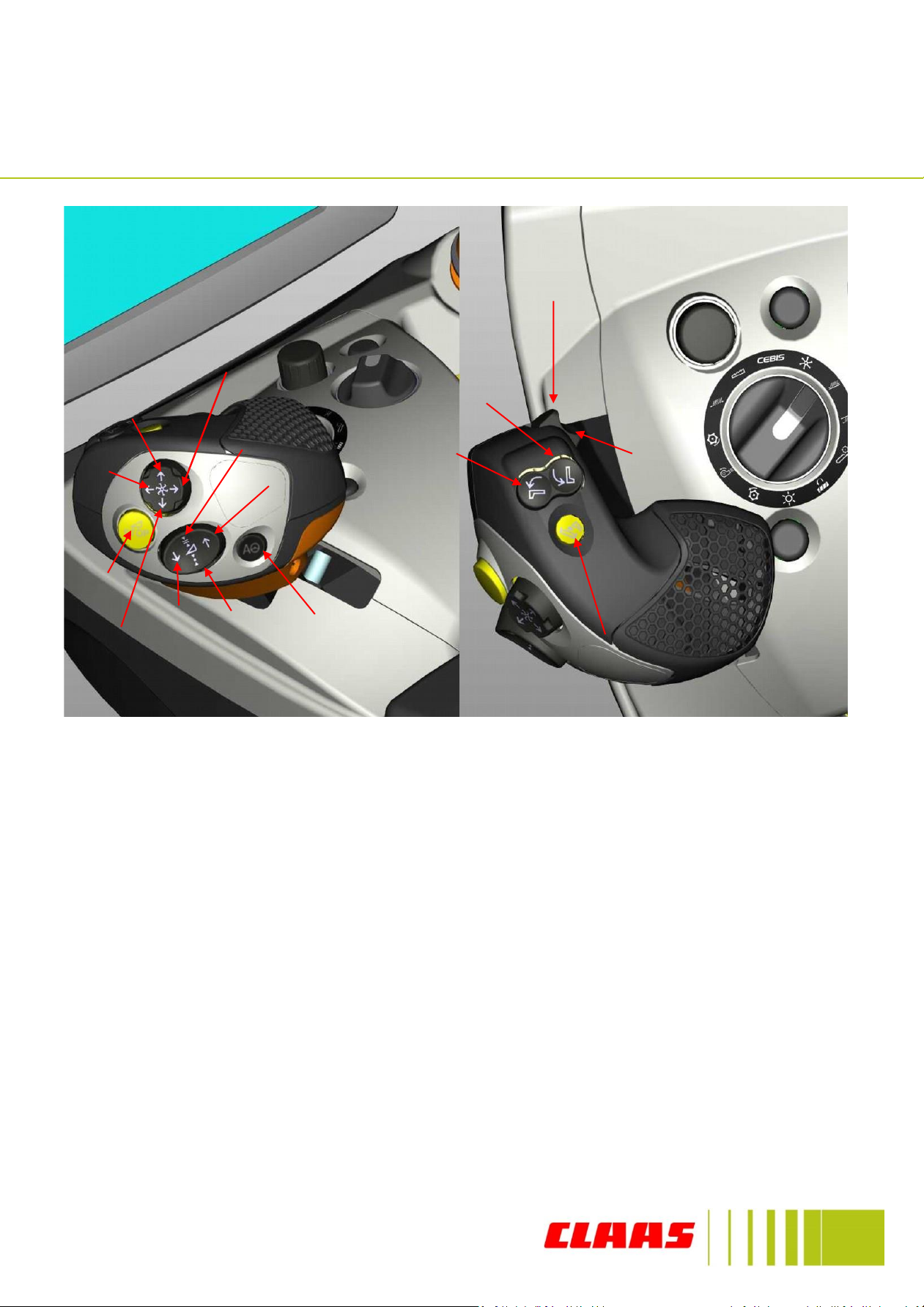
C-MOTION Multifunction lever
1b 2
3a
3b
1a
1d
1c
5
4a
4b
4c
4d
6
7H
7S
1a. Raise front attachment (2 speed) 4d. Reel aft
1b. Lower front attachment (2 speed) 5. Front attachment stop
1c. Cutting height pre-selection 6. Grain tank unloading on/off
1d. Cutterbar ground pressure 7H Extend vario table/Cross
2. Auto pilot/Laser pilot/Cruise pilot/CEMOS levelling left/hotkey
3a. Swing out unloading tube 7S. Retract vario table/Cross
3b. Swing in unloading tube levelling right/hotkey
4a. Reel lower
4b. Reel raise
4c. Reel forward
10
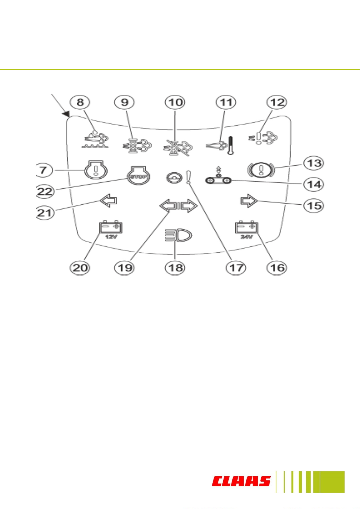
Steering column perkins
7. Engine fault indicator
8. Urea level
9. Exhaust filter loading
10. Regen deactivated
11. High exhaust temp
12. After treatment fault
13. Brake pressure warning
14. Track tension warning
15. Right indicator
16. 24v charging light
17. Emergency steering pump
18. Main beam
19. Trailer indicator
20. 12v charging light
21. Left indicator
22. Stop engine light

11
Steering column Mercedes
7. Engine fault indicator
8. Urea level
9. Not used
10. Engine de-rate
11. Not used
12. Not used
13. Brake pressure warning
14. Track tension warning
15. Right indicator
16. 24v charging light
17. Emergency steering pump
18. Main beam
19. Trailer indicator
20. 12v charging light
21. Left indicator
22. Stop engine light
12
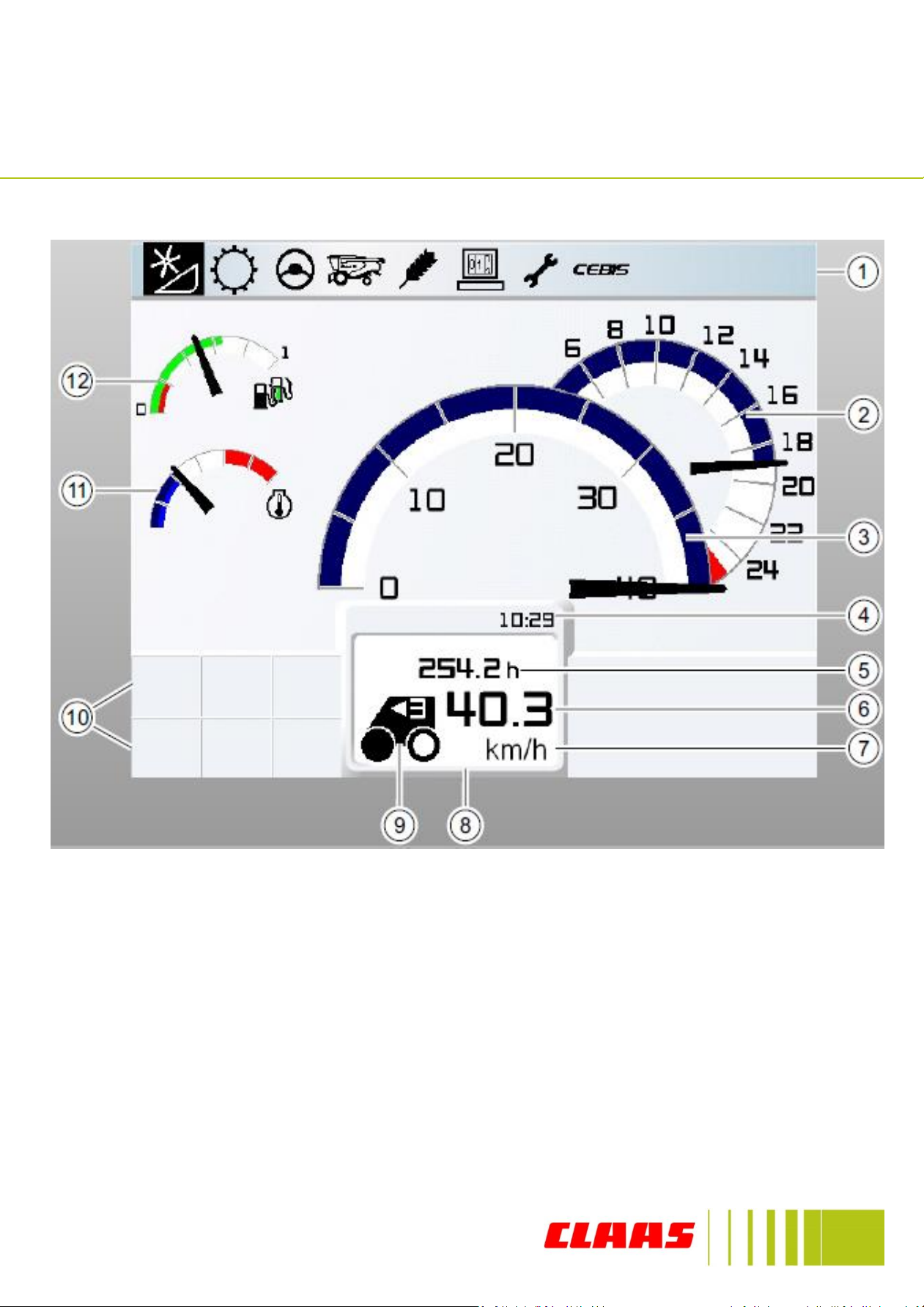
CEBIS
Road travel display Mercedes
1. Main menu
2. Engine RPM
3. Speedometer
4. Time
5. Operating hours
6. Ground speed
7. Ground speed units
8. Vehicle control display
9. Drive status
10. Message fields
11. Coolant temperature
12. Fuel (pointer)/ urea level*(green bar)
*Engine HP is reduced if urea tank is below
20%
13
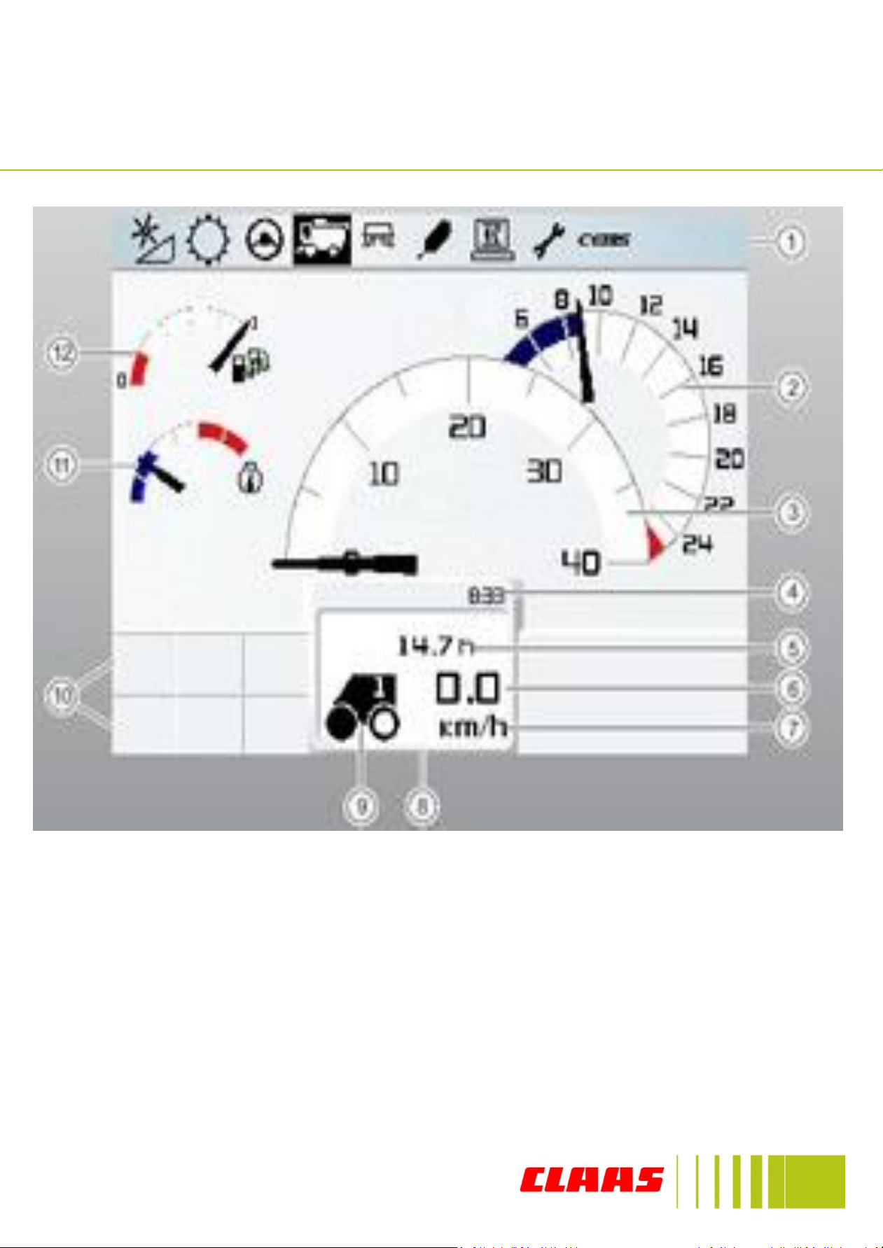
CEBIS
Road travel display Perkins
1. Main menu
2. Engine rpm
3. Speedometer
4. Time display
5. Operating hours
6. Ground speed
7. Ground speed units
8. Vehicle Control display
9. Drive status
10. Message fields
11. Coolant temperature
12. Fuel level

14
CEBIS –Harvest display
1. Main Menus
2. Broken grain
3. Non-Grain
4. Returns meter
5. Grain in returns
6. Separation monitor
7. Cleaning monitor
8. Area counter
9. Area/hour counter
10. Yield counter
11. Yield/hour counter
12. Harvest display
13. Ground speed display
14. Ground speed unit
15. Drive direction
16-18 Variable display
19. Message display
20. Cutting height control
21. Pre-set cutting height
22-23 Variable display
24. Time
15
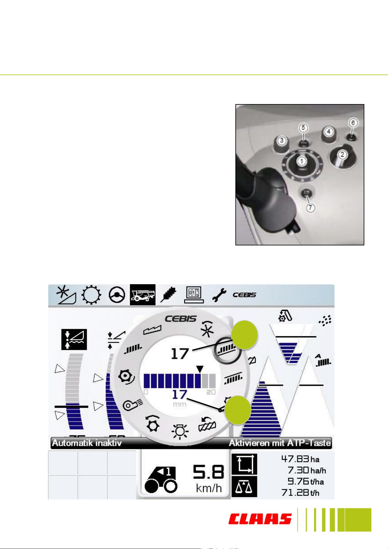
CEBIS Keys
CEBIS
Using the CEBIS rotary switch (1) the combine
settings can be adjusted. The picture below
shows the operating settings that can be
adjusted. To navigate through the settings turn
the CEBIS rotary switch (1).
Inside the CEBIS display there are 2 large
numbers, the top number (7) shows the
desired value and the lower number (8) shows
the actual value.
To adjust the value turn switch (3) left or right
to increase or decrease, after the required
setting is completed turn the CEBIS rotary
switch (1) back to the CEBIS icon on the display
screen (12 o’clock).
7
8
16
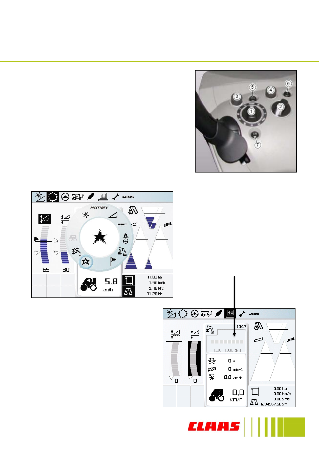
HOTKEY
HOTKEY
The HOTKEY (2) is used to adjust the more
frequently changing settings on the Combine
for example straw chopper or LASER PILOT
bias.
To adjust any of the HOTKEY values turn the
rotary switch (2) and the HOTKEY dial will
appear on CEBIS which is shown in the picture
below. Turn the dial to select the required icon
to make any adjustments.
After 5 seconds the HOTKEY dial
will disappear from CEBIS and the
settings will be displayed in the
window shown below. To change
the HOTKEY setting value turn
switch (4) either left or right to
either increase or decrease the
value.
To remove the adjusted settings
from the window turn the
HOTKEY switch (2) back to the
CEBIS (12 o’clock) position and
the previous settings will be
displayed.
17
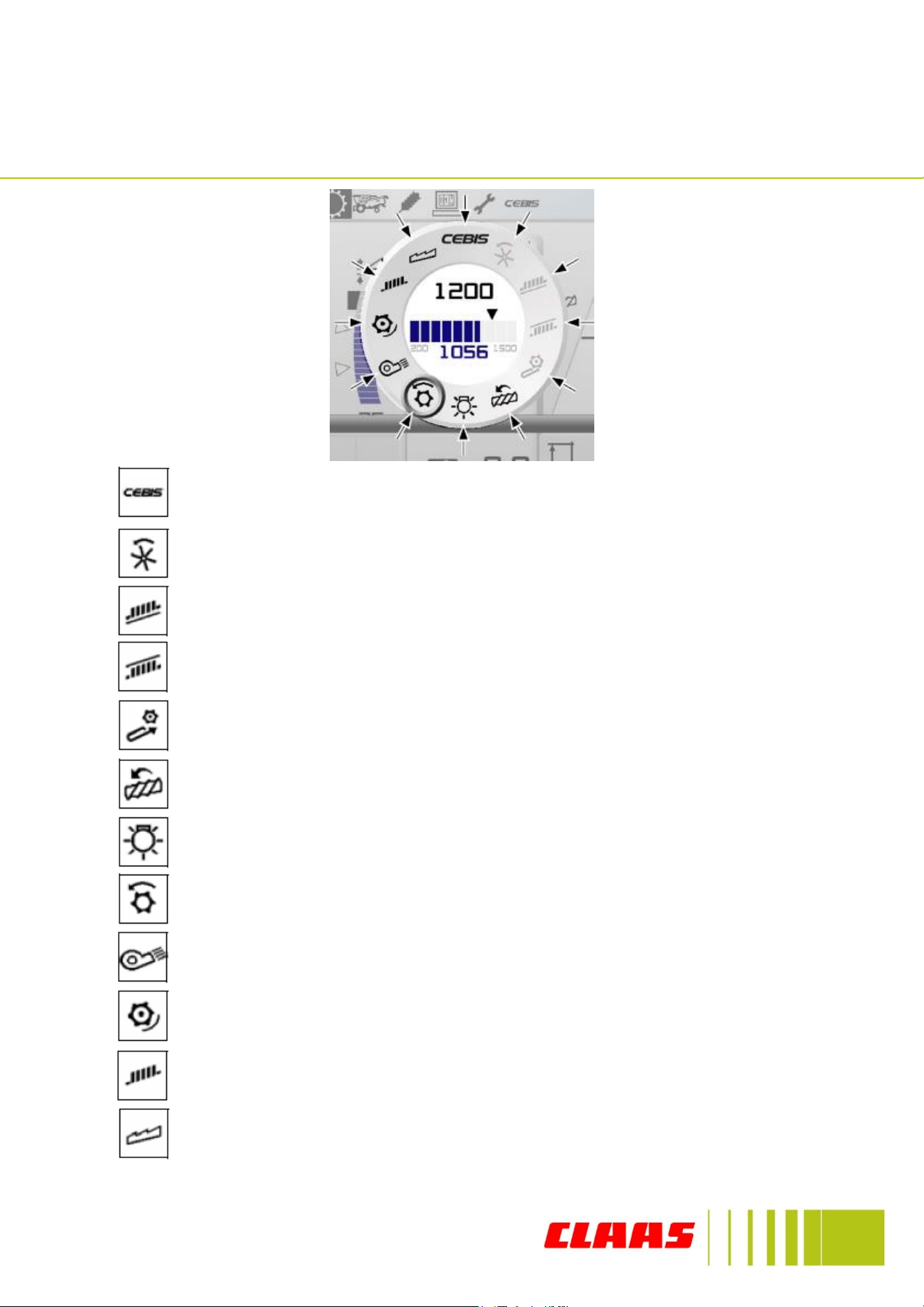
CEBIS Symbols
Exits the menu and returns to CEBIS
Manual reel speed adjustment
Top sieve adjustment
Bottom sieve adjustment
Front attachment speed adjustment (if fitted)
Rotor speed adjustment
CEBIS screen brightness adjustment
Drum speed adjustment
Fan speed adjustment
Concave clearance adjustment
Cleaning performance monitor adjustment (Sieve loss)
Separation performance monitor adjustments (Walker/rotor loss)

18
HOTKEY Symbols
LASER PILOT adjustment
Hectolitre weight adjustment
Flagging function for yield mapping
Left / Right chopper bias, Working width, Central overlap, (only with
power spreader) and crosswind compensation if fitted
Favourite crop settings
CRUISE PILOT
Automatic Reel speed, Reel height, Reel fore & aft position
Cutting height, VARIO length, End snapping plate adjustment
Partial working width adjustment
19
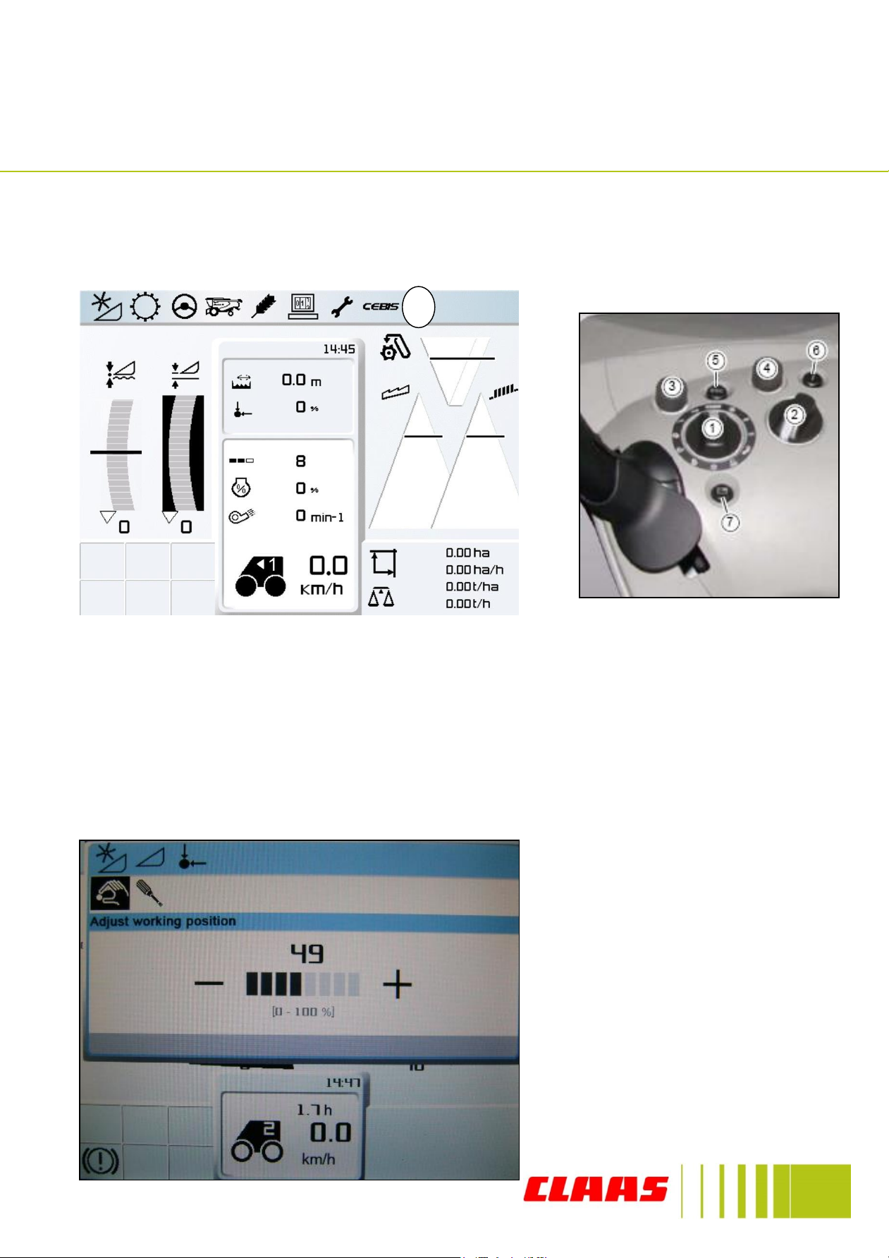
CEBIS Menu Navigation
To navigate through the CEBIS menu turn the switch (3) shown below and the
different icons at the top of the CEBIS screen will be highlighted in black (8).
When the desired menu is highlighted push switch (3) to enter it, with any menu
turn switch (3) to select the required section and push it to enter it. If a value needs
to be changed within a menu push the switch (3) to display the + - signs and turn
the switch the correct value and push it again to enter and save the value as shown
in the picture below.
To exit any of the menu within
CEBIS use the ESC button (5),
this will return the screen back
to the previous menu.
8
Table of contents
Other Claas Utility Vehicle manuals

Popular Utility Vehicle manuals by other brands


Century
Century 974W25 Installation, operation, maintenance, parts

Floe
Floe CargoMax XRT owner's manual

Mi-T-M
Mi-T-M HMT-4004-0MGH Operator's manual

Summit
Summit 84015 Instruction booklet

Yamaha
Yamaha YUM1A UMAX RALLY 2021 Owner's/operator's manual

MULTIQUIP
MULTIQUIP Whiteman series Operation and parts manual

Taylor-Dunn
Taylor-Dunn SC-100-24 Service and Replacement Parts Manual

SnowEx
SnowEx V-Maxx G2 VX-2200 Installation instructions manual

Toro
Toro 7213 Operator's manual

Jungheinrich
Jungheinrich ESD 220 operating instructions

Polaris
Polaris RANGER 570 Full Size 2016 owner's manual

Yamaha
Yamaha Yamaha Rhino 660 owner's manual