Floe CargoMax XRT User manual

1
OWNER’S MANUAL
THE ULTIMATE
“GRAB AND GO”
TRAILER!
Retain this manual for future reference.
Read and follow all safety rules and operating instructions carefully before using trailer.
Serious injury, potential death and/or mechanical failure could result from neglecting to take appropriate action.
ATTENTION ATTENTION ATTENTION
All trailer users should watch the 4 minute Basic Operations video prior to using trailer.
Go to www.oeintl.com/manuals-information and click on “Play Video”.
P/N 500-95030-00 2014-2019 1/30/20

2
We appreciate your business and hopeyou are proud ofyournewFLOE CargoMaxXRT
trailer – a pride that will continue throughout the years. If you shopped trailers before
deciding on the Floe,you probably concluded that our trailer has numerous features not
commonlyfound onothers.
At FLOE International, we take great pride in providing the highest quality trailer, with the latest state-of-the-art
features,atan affordable price.Each yearwe implement improvements to ourproduct lines to ensure thatwe are on the
“leadingedge”andprovidingthebestavailabletrailer.
We are condentyourFLOE trailerwill provide youwith years of trouble-free trailering,and that ifyou decide to buy
anothertrailer,itisbecauseyouwantanotherFLOEmodel.
Please take the time to read and understand this owner’s manual before towing your new trailer.The information
offered herewill havea directimpactonyoursafety,the safetyofothers,andthedependabilityofyourtrailer.
Thankyou forchoosingFLOE.
Sincerely,
WayneFloe,CEO–FloeInternational
For assembly instructions and part numbers
refer to assembly instructions book.
Important Safety Information ................................................... 3
Reporting Safety Defects ............................................................ 3
Hitch Selection............................................................................. 4
Hitch Coupler Adjustment......................................................... 4
FLOE Tilt Clamp ......................................................................... 5
Secure Your Trailer...................................................................... 5
Trailer Lighting System............................................................... 6
Electric Brake Option ................................................................. 7
Capacity & Weight Distribution................................................ 8
Proper Loading & Unloading .................................................... 9
Securing the Load...................................................................... 10
Accessories ................................................................................. 11
Changing Tires........................................................................... 12
Inspections & Maintenance ..................................................... 13
Frequently Asked Questions ................................................... 14
Tire Safety Information .......................................................15-25
Parts & Exploded Views ......................................................26-46
Warranty & Warranty Registration....................................47-48
Contents
Serious injury, potential death or
mechanical failure could result from
neglecting to take appropriate action.
IMPORTANT SAFETY INFORMATION
WARNING
Your safety and the safety of others is very important. We have provided many important safety messages in this manual
and on your trailer. Always read and obey all safety messages.
If you do not understand any of these instructions, please ask your dealer or call FLOE customer service at 800-336-6337.
is is the safety alert symbol. is symbol alerts you to hazards that can cause
serious injury or potential death to you and others, plus damage to the
trailer. All safety messages will be preceded by the safety alert symbol
and the word “WARNING” or “CAUTION”.
All safety messages will identify the hazard and tell you how to reduce the chance of injury.
This manual includes the latest information at the
time it was printed. We reserve the right to make
changes in the product after that time without
notice. Keep this manual so it will be available to
whoever is using this product.
Failure to follow this manual’s instructions may result in
damage to your trailer or vehicle, and could cause severe or
fatal injury to you or others.
WARNING

3
Important
Safety Information
SAFETY PRECAUTIONS
It is the owner’s/operator’s responsibility to check the following
items each time before towing trailer.
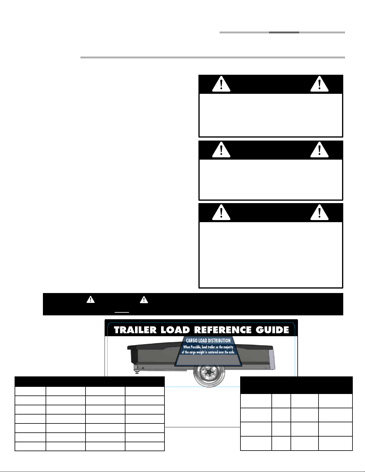
• Never exceed the trailer or tongues maximum load capacity
• When possible, position load so the weight is centered over
the axle
• Do not rely on the tailgate ramp to contain or stop cargo
from sliding or rolling out of the trailer. Use good judgment
and secureallcargo.Failuretodosomayresultinaroadhazard
which could cause serious injury and/or death.
• Reduce speed and/or cargo weight when traveling on rough
roads.
• Overloading and improper use of this trailer could cause
structural damage, product failure and/or severe or fatal
injury.
• Monitor load at regular intervals while traveling.
• Check that load is positioned to apply equal weight to all tires.
• Check that load is secured so it will not move while underway.
• Check that no structural damage to trailer exists, do not use
if damaged.
• Check that trailer is level with tow vehicle.
• Check that trailer coupler is properly adjusted and securely
attached to the hitch ball.
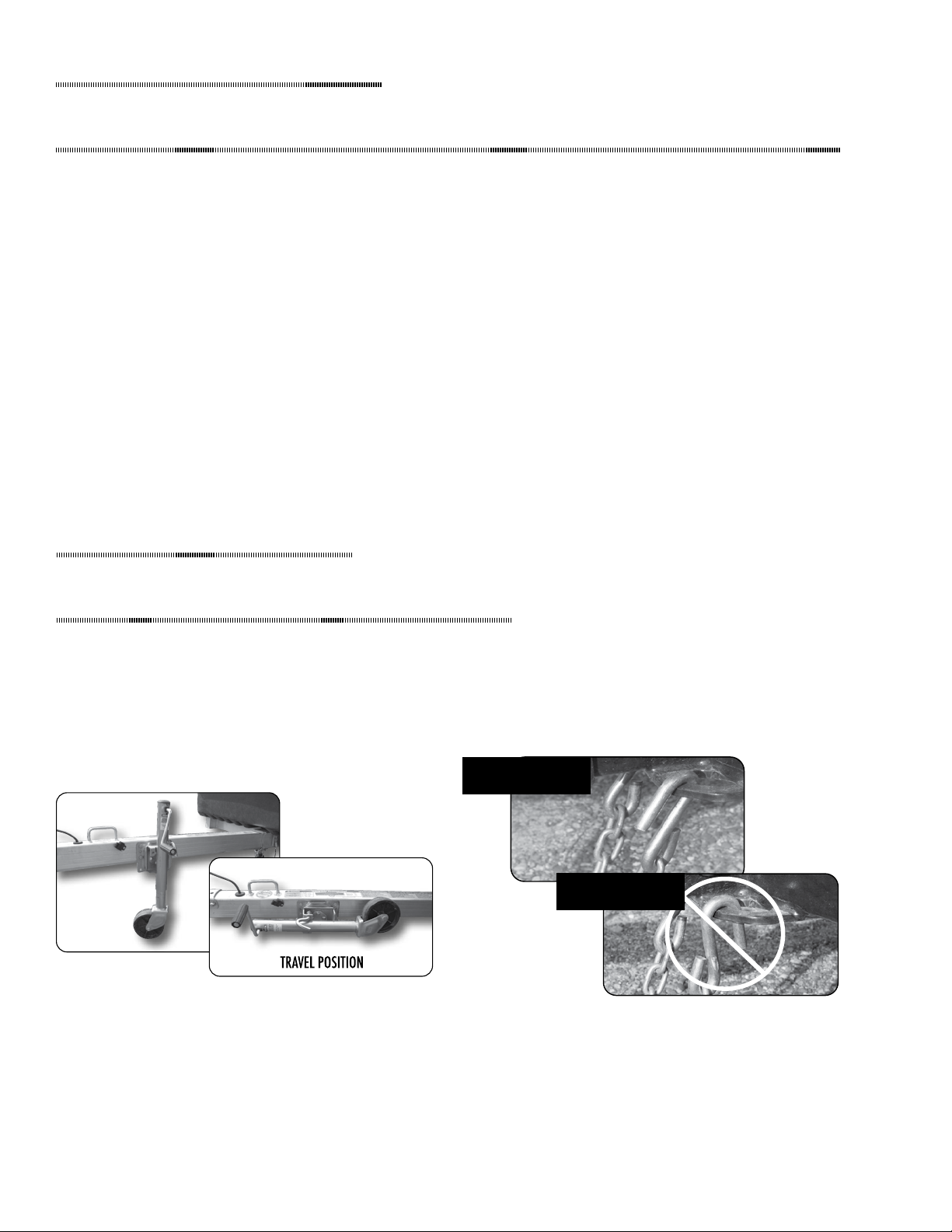
• Check that safety chains or cables are attached properly.
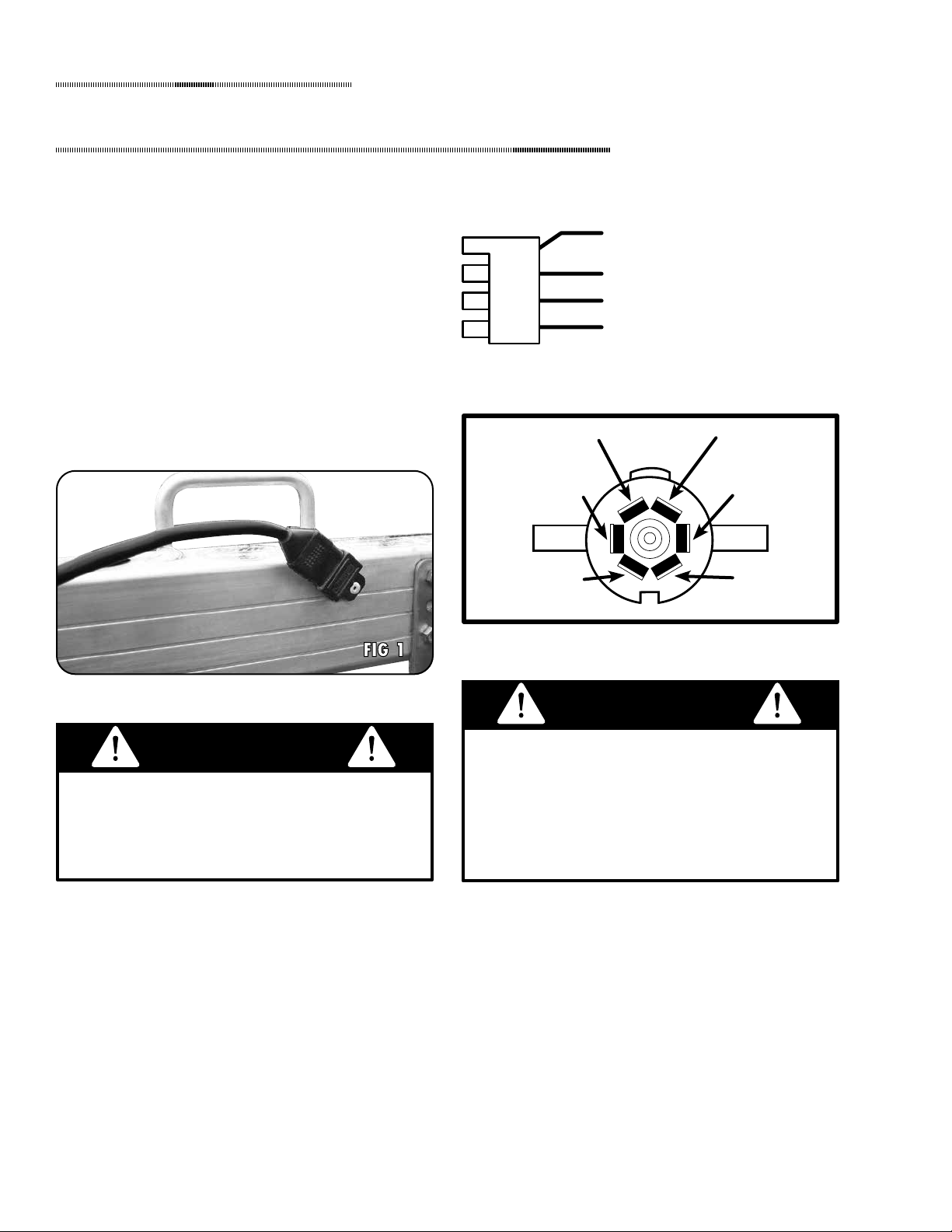
• Check that all lights are operating correctly.
• Check that bed locking system (tilt clamp) is properly secured.
Reporting Safety Defects
If you believe that your trailer has a defect which could cause a
crash or could cause injury or death, you should immediately
inform the National Highway Trac Safety Administration
(NHTSA) in addition to notifying FLOE International, Inc.
at 1-800-336-6337.
If NHTSA receives similar complaints, it may open an
investigation, and if it nds that a safety defect exists in a
group of vehicles, it may order a recall and remedy campaign.
However, NHTSA cannot become involved in individual
problems between you, your dealer, or FLOE International, Inc.
To contact NHTSA, you may either call the Auto Safety Hotline
toll-free at 1-888-327-4236 (TTY: 1-800-424-9153); go to
http://www.safercar.gov; or write to: NHTSA, US Department
of Transportation, 1200 New Jersey SE, Washington, D.C.
20590. You can also obtain other information about motor
vehicle safety from http://www.safercar.gov.
READ AND UNDERSTAND THE OWNER’S MANUAL AND ALL WARNINGS/SAFETY PRECAUTIONS BEFORE USING TRAILER.
If the trailer is not assembled, installed, or operated properly, mechanical failure as well as serious injury or death could result. See
to it that all users understand that this trailer requires the use of good judgement and the knowledge of its dangers and limitations.
LUG NUTS ON NEW WHEELS SHOULD BE
RE-TORQUED AFTER THE FIRST 10-25 AND 50
MILES. CHECK PERIODICALLY THEREAFTER.
This should be done as clamping loads can change following
the initial installation due to the metal compression/
elongation or thermal stresses affecting the wheels as they
are breaking in, as well as to verify the accuracy of the
original installation.
WARNING Maximum tongue weight capacity is 125 lbs for the 8-57,
220 lbs for the 9.5-73, 11-73, 13-73 & 13-73 Tandem No
Brake, and 440 lbs for the 13-73 Tandem E2 Brake version.
MAXIMUM CARGO CAPACITY FOR EVENLY
BALANCED LOADS IS 1800 LBS (XRT 8-57);
2200 LBS (XRT 9.5-73, 11-73, 13-73 & 13-
73 TANDEM NO BRAKES; 3470 LBS FOR 13-
73 TANDEM WITH ELECTRIC BRAKES. Exceeding
this load capacity could cause product failure and/or injury
and death.
WARNING
• Check that tires are inated to correct pressure and not
excessively worn.
• Check that lug nuts on each wheel are tight.
• Check that wheel bearings are properly tightened and greased.
• CargoMax trailers comply with all federal laws and
regulations. Laws in individual states vary, and some states
may have laws that are more stringent than federal laws.

4
Using your FLOE trailer
Hitch Selection & Use
When selecting a hitch, there are four important things to
keep in mind:
• Load capacity -- Load should never exceed the load
capacity of your hitch or tow vehicle.
• Ball/hitch -- All FLOE tilt trailers use 2” couplers. Make
sure trailer is connected to a properly secured 2” ball and
hitch.
• In-set or out-set hitch -- FLOE recommends an out-set or
receiver-type hitch (See below).
• Hitch Height -- Hitch should be set so the trailer is level.
ese illustrations show that a trailer’s turning radius is
signicantly reduced when towed by vehicles equipped with
an “in-set” hitch. To reduce the risk of tongue damage, we
recommend the use of an “out-set” or “receiver-type” hitch.
When turning or backing up, the vehicle operator must
exercise good judgement. The manufacturer will not be
responsible for damage from “jackkning.” Jackkning is
damage that results from the tongue or trailer coming in
contact with the tow vehicle.
WARNING
Out-set Hitch (Recommended)
Bumper
In-set Hitch (NOT Recommended)
Bumper
When connecting your trailer to the towing vehicle, it is
important that your hitch coupler is adjusted with the
correct amount of force for both smooth and safe trailer
performance. A loose coupler could disconnect and cause
product damage and/or serious injury or death.
WARNING
Using your FLOE trailer
Hitch Coupler Adjustment
All FLOE models have a lever lock hitch coupler. With a lever lock coupler, the amount of locking force can be adjusted to the
diameter of the hitch-ball. A coupler that is adjusted too tight will make it dicult to push down on the lever lock and may cause
vibration from the trailer to the tow vehicle. A coupler that is too loose runs the risk of coming o the hitch-ball. When properly
adjusted you should be able to easily push down on the lever
lock but yet not have any rattle between the hitch-ball and
coupler when you apply upward force. To change the amount
of locking force against the hitch-ball:
1. Release the hitch coupler locking lever (to its straight up
position).
2. Locate the adjustment nut on the bottom of the hitch coupler.
3. Rotate the nut on the threaded sha with a 3/4” socket.
Turn counter-clockwise to decrease tightness, or clockwise
to increase tightness.
4. Re-mount the trailer coupler on the hitch-ball.
5. Push down the hitch coupler locking lever to its original
locking position.
6. Repeat steps 1 through 5 until a snug t is obtained.
Do not attempt to hook up or use any trailer that has
structural damage. It is the operators responsibility to
inspect the trailer before each use. A trailer failure could
cause severe or fatal injury.
WARNING
Pulling a trailer that is not level could greatly affect the
trailer’s performance and create an uncomfortable and
dangerous situation while towing. It could also create
excessive or negative tongue weight which can cause
either tongue or axle damage.
WARNING

5
Using your FLOE trailer
Tilt Clamp
Failure to properly tighten tilt clamp and secure safety cotter
pin before towing trailer could cause the trailer to tilt while
in transit. A trailer tilting while in transit could cause product
failure, and/or severe or fatal injury.
WARNING
Note: If your trailer does not stay in the tilted position:
1. e tongue mounting bolt may not be tightened to optimal
tension. Torque to 60 Ft/Lbs
e FLOE tilt clamp eliminates the hassle and rattle of a hitch
pin design. To tilt, simply loosen the handle screw, remove
the safety cotter pin, and slide clamp forward. When nished
loading or unloading, slide clamp back
on, replace cotter pin, and tighten handle
screw.
1. Loosen knob on underside of tilt
clamp.
2. Remove safety cotter pin.
3. Slide clamp forward. If the trailer is
used without tailgate ramp, slide the
limiter strap bracket ahead along with
the tilt clamp. is will allow the bed to
tilt back until it touches the ground.
4. To tilt trailer push down on rear of
trailer.
5. Load trailer (see section on “Proper
Loading and Unloading”)
6. Tilt trailer back to horizontal position
by pushing down on front of trailer.
7. Slide tilt clamp back to original position,
replace safety cotter pin, and tighten
the knob enough to prevent it from
loosening during use.
Trailer in
limited tilt mode
using limiter strap
and tailgate ramp
Trailer in full tilt
dump mode
Trailer in level ramp mode -
slide clamp forward to tilt
Tilt Clamp bolt knob must be cleaned and greased annually
to prevent signicant corrosion. Failure to do so can result
in repairs not covered by the warranty.
WARNING
Greasing the Tilt Clamp
Tighten knob bolt. Using Q-Tip or small brush, apply anti-
seize to as many threads as possible, and generously to the
top of the nut.
Loosen knob bolt as much as possible. Last two threads are
deformed on purpose - DO NOT FORCE PAST THEM - and
apply anti-seize generously. Slide clamp back on and tighten
knob as usual.
2
1

6
Using your FLOE trailer
Trailer Lighting System
WIRE HARNESS CONNECTOR
• Your trailer is equipped with a plug-in receptacle on the
trailer tongue to keep the electrical connector protected
when not in use as shown (FIG 1).
• To ensure trouble-free use, periodically inspect end plug for
tight, corrosion-free contact and apply electrical grease as
necessary to prevent future corrosion.
e wiring diagrams below provides the information
needed for wiring the towing vehicle harness/connector. It is
important that the proper connections be made and that the
system is tested before using your trailer.
White - Grounds all lights
Brown - Front & rear marker lights
& tail lights
Yellow - Le turn/brake light
Green - Right turn/brake light
Lights must be properly connected to the tow vehicle and
checked prior to each trailer use. Do not use trailer on
any public road without all lights functioning properly.
Malfunctioning lights fail to give other motorists proper
notication of your actions and location which can cause a
serious or fatal accident.
WARNING
Make sure the wiring harness for the lighting system is
long enough so that it is does not become unplugged when
turning sharp corners. Disconnected lights can cause a
serious or fatal accident.
WARNING
Brown
Running Lights
Yellow
Left Brake/Turn
White
Ground
Black
Battery Charge
Green
Right Brake / Turn
Blue
Electric Brakes
NON-BRAKE HARNESS
ELECTRIC BRAKE HARNESS

7
For optimal performance of the axles with electric brakes, the
trailer brakes need to be synchronized with the towing vehicle
brakes, and the break-away system needs to be properly
maintained.
SYNCHRONIZATION
To synchronize the trailer and tow vehicle brakes, make several
full stops from a speed of about 20 mph, and then adjust the
brake controller as required. Repeat as necessary until the
brakes function optimally. With proper synchronization, the
trailer should not yank on the tow vehicle or push on it while
braking.
BREAK-AWAY SYSTEM
Trailers with electric brakes are equipped with a break-away
system that will bring the trailer safely to a stop in the event
that the trailer becomes disconnected while driving.
e break-away system is powered by a battery box that
charges automatically when the 7-way plug is attached to the
tow vehicle. e break-away system also contains a break-
away switch with a removable pin attached to a cable. e pin
must be installed in the break-away switch and the cable must
be attached to the tow vehicle while driving. In the event that
the trailer becomes disconnected from the tow vehicle while
driving, the pin will be removed from the break-away switch,
which will activate the electric brakes.
To test the unit, pull on the cable to remove the pin from the
break-away switch, and verify that the electrical brakes have
been activated. e break-away system should be tested prior
to each trailer outing.
Using your FLOE trailer
Electric Brake Option
Model Dimensions
GVWR
lbs/kgs
Cargo Load
lbs/kgs
Net Wt.
lbs/kgs Standard Tires Upgrade Tire
Max.
tongue wt. -
lbs/kgs
Tire
Speed
Rating
XRT 8-57 8’ x 57” 2140/971 1800/816 290/132 5.30 x 12” -C 5.30 x 12” -C Mag 125/57 65 mph
XRT 9.5-73 9.5’ x 73” 2800/1270 2200/998 480/218 205-75R14 Steel 205-75R14 Alum 220/100 75 mph
XRT 9.5-73 9.5’ x 73” 2990/1356 2380/1080 520/236 205-75R14 Steel 205-75R14 Alum 300/136 75 mph
XRT 11-73 11’ x 73” 2800/1270 2200/998 540/245 205-75R14 Steel 205-75R14 Alum 220/100 75 mph
XRT 11-73 11’ x 73” 2990/1356 2380/1080 580/263 205-75R14 Steel 205-75R14 Alum 300/136 75 mph
XRT 13-73 13’ x 73” 2800/1270 2200/998 570/259 205-75R14 Steel 205-75R14 Alum 220/100 75 mph
XRT 13-73 13’ x 73” 2990/1356 2380/1080 610/277 205-75R14 Steel 205-75R14 Alum 300/136 75 mph
XRT 13-73T 13’ x 73” 2990/1356 2200/998 780/354 205-75R14 Steel 205-75R14 Alum 440/200 75 mph
XRT 13-73T 13’ x 73” 4400/1996 3470/1574 930/422 205-75R14 Steel 205-75R14 Alum 440/200 75 mph
Loading your FLOE trailer
Capacities & Weight Distribution
Trailers cargo load capacity is reduced by the weight of additional options such as Gate Keepers and/or Cargo Covers.
NO
BRAKES
BRAKES
2014
- 2020
2014
- 2020
2014
- 2020
2021
2021
2021

8
Loading your FLOE trailer
Capacities & Weight Distribution
TONGUE WEIGHT CAPACITY
• It is extremely important to never exceed the maximum
tongue weight capacity. Over loading the tongue could
cause it to bend or break. A broken tongue could cause a
serious or fatal accident.
• Loads should be placed on the trailer so that proper weight
is applied to the tongue. e ideal tongue weight should
be 6% of the cargo weight but never over the max tongue
weight. Increase or decrease the tongue weight by moving
the load forward or backward.
• It is the users responsibility to understand what 125/220
pounds or less is.
SECURING TONGUE JACK
Tongue jack must be properly secured in the travel position
before moving the trailer (see image below). Simplies
coupling and uncoupling to a vehicle. Swivel wheel enables
easy trailer movement by hand. Jack easily clamps to tongue
and pivots up for travel.
CORRECT
INCORRECT
Using your FLOE trailer
Secure Your Trailer
CONNECTING SAFETY CHAINS
Safety chains must be hooked up every time the trailer is in use.
To connect safety chains properly be sure they cross each other
and the open end faces the trailer (see images below).
CARGO WEIGHT DISTRIBUTION
• It is extremely important to never exceed the maximum
cargo capacity.
• Maximum cargo capacities are for evenly distributed loads
which place the majority of the cargo’s weight directly
over both wheels evenly. A good example of this would be
hauling several sheets of plywood.
• Loads should also be placed to distribute equal weight to
both tires. is will balance your load and give you the best
wear on your tires.
• Never place more than 50% of the total cargo capacity on
one side of the trailer.

9
Loading your FLOE trailer
Proper Loading & Unloading
Failure to follow the listed steps when loading or unloading
could result in damage to your trailer, tow vehicle, the load
you are hauling, and/or cause possible severe or fatal
injury to yourself and others.
WARNING
Never exceed the cargo load rating of your trailer. When
the trailer is loaded with dense or wet materials the load
can easily exceed the rated cargo capacity. Do not allow the
volume of the trailer to determine the load of your trailer.
Always verify the weight of the cargo you are hauling.
Failure to do so can cause severe damage and/or failure to
the hauling vehicle, the trailer and nearby vehicles.
WARNING
1. Prior to using the trailer loaded or unloaded it is imperative
that no structural damage exists. Do a visual check to ensure
that none of the structural components are bent or cracked.
• If damage does exist do not use the railer until it has been
repaired by an authorized repair service.
• Under no circumstances should an attempt be made to
straighten a bent structural component.
2. Never load or unload your trailer unless it is properly
connected to your tow vehicle.
3. Always ensure that tow vehicle and trailer are parked on
level, even ground. Loading while parked on an incline or
uneven ground may result in structural damage to trailer.
4. Ensure the trailer is fully tilted and that it will stay in the
tilted position until you have driven on to it.
5. Never move tow vehicle with the trailer in the tilted
position. Doing so may result in structural damage to the
trailer
6. Never load moving items such as ATVs and lawn mowers
at speeds greater than 5 mph.
7. Never allow the load to cause the trailer to tilt down quickly
and with a lot of force. is could cause structural damage
to the tongue, tongue receiver and cross members.
8. Aer loading, make sure the tilt clamp is secure and will
not work itself loose while being towed. Make sure the
safety pin is attached.
9. Always test your footing before walking on the trailer’s deck.
It may get very slippery in cold, wet and snowy weather.
Wood Mulch = 1 1/4 yard
Pine Lumber = 10” deep
Shell Corn = 30 Bushels
Firewood = 1 1/8 Face Cord (4’x8’x16”)
Peat = 1 1/8 yards
Black Dirt = 3/4 yard
Gravel = 1/2 yard
Sand = 1/2 yard
164
23
33
31
This information should only be used as
a reference to assist in determining
how much you can haul.
Weights are based on
normal moisture content.
When traveling on rough roads, reduce cargo weight and
speed to avoid causing structural damage to the trailer.
Failure to do so could cause product failure and/or injury
and death.
WARNING
Material XRT 8-57 XRT 9.5,11,13 XRT 13-73 T BRAKE
Wood MulchWood Mulch 1 1/4 Yard 1 1/2 Yard 2 3/8 Yards
Shell CornShell Corn 30 Bushels 36 2/3 Bushels 57 7/8 Bushels
FirewoodFirewood 1 1/8 Face Cord 1 3/8 Face Cord 2 1/8 Face Cord
PeatPeat 1 1/8 Yards 1 3/8 Yards 2 1/8 Yards
Black DirtBlack Dirt 3/4 Yard 1 Yard 1 1/2 Yards
GravelGravel 1/2 yard 3/5 Yard 1 Yard
SandSand 1/2 yard 3/5 Yard 1 Yard
Material XRT
8-57
XRT
9.5,11,13
XRT
13-73 T BRAKE
Pine BoardsPine Boards
2’x4’x8’2’x4’x8’
164 200 315
SheetrockSheetrock
4’x8’x5/8”4’x8’x5/8”
23 28 44
PlywoodPlywood
4’x8’x1/2”4’x8’x1/2”
33 40 63
Sod RollsSod Rolls
18”x72”18”x72”
31 38 60
WARNING WHEN LOADING, ENSURE YOUR LOAD IS PROPERLY SECURED
& EXIT THE TRAILER FROM THE FRONT TO AVOID TILTING THE TRAILER. FAILURE TO DO SO MAY RESULT IN SERIOUS INJURY OR DEATH.

10
Loading your FLOE trailer
Securing The Load
Do not ever strap the load to or over the side of the trailer
bed. Doing so may lead to a dangerously unsecured load
and may cause damage not covered under your warranty.
WARNING
TIE DOWN INSTRUCTIONS
1. Use any of the tie down D-rings in the trailer bed as needed
to safely secure your load.
• e maximum capacity of each 8-57 D-ring is 500 lbs of
cargo weight. For instance: an ATV weighing 800 lbs should
be secured to four tie down loops as shown in (FIG. 4).
Maximum capacity of each D-ring on all other CargoMax
trailers is approximately 1600 lbs.
2. Cargo must be secured so that tie down restraints can not
become loose while traveling.
• If the load were to shi forward or backward it could
cause excessive tongue weight or negative tongue weight.
Either situation could be dangerous.
3. When securing hooks through the SIDE of the tie down
D-rings, either direction is appropriate -- see (FIG. 1).
4. When securing hooks through the TOP of the D-rings,
make sure the hook faces up -- see (FIG. 2). NEVER use
hooks in the position shown in (FIG. 3) as this provides a
greater chance of failure.
5. Do not place straps from the outside of the trailer over the
bed as you may cause damage to the trailer bed.
Ensure that the load is adequately secured. Load may
become loose during travel. Check your load while traveling.
Unsecured loads can cause product damage, road hazards
and/or cause severe injuries and death.
WARNING
When securing cargo, consider how it will behave if
extreme acceleration, deceleration (fast braking),
swerving, or poor road conditions occur. A load that
shifts forward or backward may cause an unsafe
situation which could result in product damage, severe
injuries or even death.
WARNING
SECURING THROUGH SIDE OF D-RING
FIG. 1FIG. 1
✔✔✔
FIG. 2FIG. 2
SECURING THROUGH TOP OF D-RING
FIG. 3FIG. 3
PROPER USE OF TIE-DOWN D-RINGSPROPER USE OF TIE-DOWN D-RINGS
FRONTFRONT REARREAR
FIG 4FIG 4

11
Procedure for
Aluminum Tailgate Ramp
When using the tailgate ramp, the trailer can either be le in regular (upright) position, or partially tilted using the limiter strap.
is creates the perfect angle for low clearance items.
Tailgate ramp removes in
seconds with no tools.
Simply tilt back and remove.
To lower tailgate ramp,
simply squeeze the spring-
loaded center latch.
Lubricating Tailgate Latch Pins
Tailgate latch pins must be regularly inspected, cleaned and lubricated with a spray silicone-based lubricant to prevent binding.
Failure to do so can result in repairs not covered by the warranty.
Upon re-installation,
verify ramp hinges pin
are fully seated in trailer
hinges, failure to do so
may result in damage to
trailer hinge(s)

12
Do not rely on the tailgate ramp to contain or
stop cargo from sliding or rolling out of the
trailer. Use good judgment and secure all cargo.
Failure to do so may result in a road hazard which could
cause serious injury and/or death.
WARNING
MAG WHEEL
Dress up your CargoMax
with these stylish mag
wheels. Always look
great and will never
need painting.
Optional Accessories
Procedure for
Changing Tires
CHANGING TIRES
1. Start all lug nuts by hand with the beveled side of the lug
nut toward the wheel to prevent cross-threading and to
ensure proper nut-to-rim seal.
2. Tighten bolts in the sequence detailed tothe torque specied
in the table below.
3. Inate tires to proper PSI as noted on the sidewall of the
tire.
4. Lug nuts on new wheels must be re-torqued aer the rst
10-25 and 50 miles. Check periodically thereaer.
Improper tire pressure can create severe
dangers. Be sure your tires are always
properly inated. The proper pressure for your
tires can be found on the side wall of tire.
WARNING
Change worn tires. A tire failure could result
in an uncontrollable road hazard.
WARNING
LUG NUTS ON NEW WHEELS SHOULD BE
RE-TORQUED AFTER THE FIRST 10-25 AND 50
MILES. CHECK PERIODICALLY THEREAFTER.
This should be done as clamping loads can change following
the initial installation due to the metal compression/
elongation or thermal stresses affecting the wheels as they
are breaking in, as well as to verify the accuracy of the
original installation.
WARNING
CargoMax Model Steel Rims Aluminum Rims
8-578-57 50-75 ft/lbs 90-120 ft/lbs
9.5-73, 11-73, 13-73 & 13-73 Tandem9.5-73, 11-73, 13-73 & 13-73 Tandem 90-120 ft/lbs 90-120 ft/lbs
CargoMax LUG NUT TORQUE SPECIFICATIONS
4
2 5
3
1

13
It is very important to read and follow these maintenance procedures to help avoid trailer failure. Any trailer failure resulting
from improper maintenance may void your warranty.
Procedure for
Inspections & Maintenance
COMPONENT INSPECTIONS & MAINTENANCE AVOID
Structure/Frame a) Do a visual check to ensure that none of the structural
components are bent or cracked before towing. If damage
does exist do not use the railer until it has been repaired by
an authorized repair service.
a) Loading the trailer in an unbalanced
fashion (heavy on one side).
b) Exceeding capacities of trailer and
tongue.
Wheel Hubs a) Adjust wheel bearings within the rst 100 miles and every
2,000 miles, or annually thereaer, whichever comes rst.
(Inspect bearings, seals, and races - replace if worn.) To
check for wear, jack up the trailer and pull on each wheel to
see if there is any in and out play or “slop.”
a) Getting sand in hubs or bearings.
b) Neglecting to grease hubs.
Wheel Lugs a) Lug nuts on new wheels should be re-torqued aer the rst
10-25 and 50 driving miles.
is should be done as clamping loads can change following
the initial installation due to the metal compression/
elongation or thermal stresses aecting the wheels as they
are breaking in, as well as to verify the accuracy of the
original installation.
a) Leaving wheel lugs un-torqued for
longer than 50 driving miles with
new wheels.
Axle a) Inspect trailing arms to make sure they are straight. a) Leaving loaded for long periods
Tires a) Keep tires properly inated.
b) Inspect periodically. (Replace when necessary)
a) Leaving loaded for long periods
b) Driving with worn tires.
Aluminum
Surfaces
a) Rinse periodically with water, particularly if driven on
“salted” roadways.
b) Remove grease, oil and dirt by scrubbing with so bristle
brush and mild detergent. Rinse with clean water.
a) Harsh, abrasive cleaners.
b) Bolting or hard-mounting dissimilar
metals to aluminum surfaces.
Molded Bed a) Visually check for cracks. a) Storage in direct sunlight.
Electrical System a) Check that all lights are functioning properly before towing.
b) Periodically check for build-up of oxidation or corrosion
and clean when necessary. Use electrical grease in all wire
and bulb connections to help prevent corrosion.
a) Leaving electrical connections
exposed to elements and potential
abrasions.
Tailgate
Latch Pins
a) Remove debris from pins and lubricate with a silicone-based
spray.
a) Neglecting to lubricate pins for long
periods.
Tilt Clamp Knob a) Remove debris and apply grease to knob threads. a) Neglecting to grease threads for long
periods.
A COMPLETE INSPECTION AND LUBRICATION OF THE WHEEL HUBS IS REQUIRED
EVERY 3,000 MILES OR 6 MONTHS. TO LUBRICATE THE WHEEL HUBS, REMOVE
THE RUBBER PLUG, PLACE GREASE THROUGH THE EXPOSED GREASE FITTING, AND
REPLACE THE RUBBER PLUG. USE EXXON RONEX MP LITHIUM COMPLEX GREASE
OR EQUIVALENT.
AXLE MAINTENANCE

14
Trouble Shooting
Questions & Answers
WHAT CAN CAUSE VIBRATION IN MY TOW
VEHICLE?
1. Over-tight hitch coupler -- See procedure for adjusting hitch
coupler earlier in this book.
2. Loose or worn wheel bearings -- See procedure for replacing
wheel hub earlier in this book.
3. Loose wheels -- See procedure for changing tires earlier in
this book.
4. New tires -- It is possible that the new tires are out of round.
Once they are inated to the proper PSI and used for a
short period of time on a loaded trailer, they should work
themselves round. New tires that are still out of round aer
an ample break in period may be defective and need to be
replaced. Call the tire manufacturer or your local FLOE
dealer for replacement.
5. Unbalanced wheel hubs -- If your tires are balanced and not
out of round this may be the problem. Replace if necessary.
WHY DOES MY TRAILER SWAY OR WHIP?
1. Trailer is not being towed level -- Refer to hitch selection
and use section of this manual.
2. Not enough tongue weight -- Refer to loading and unloading
section of this manual.
3. Overloaded trailer -- Refer to loading and unloading section
of this manual.
4. Too much tongue weight -- Refer to loading and unloading
section of this manual.
WHY ARE MY TIRES WEARING UNEVENLY?
1. Unequal side-to-side loading -- Refer to Proper Loading
and Unloading section of this manual.
2. Tires not inated to proper PSI
3. Wheel bearings are not properly tightened & oiled.
CAN I REPLACE MY TIRES WITH LARGER ONES?
1. No, the 8-57 CargoMax was designed for use with 5.30 x
12”-C tires and these may not be substituted for a larger size.
A 12” mag wheel upgrade is available.
2. e 9.5-73, 11-73, 13-73 & 13-73 Tandem were designed for
use with 205-75R14 tires and these may not be substituted
for a larger size. A 14” mag wheel upgrade is available.
WHERE DO I FIND MY VIN TAG?
1. e VIN tag is located under the bed of the CargoMax – on
the tongue mount – on the driver’s side of the trailer.
WHY DO I KEEP BLOWING FUSES WHEN I
CONNECT OR USE MY TRAILER LIGHTS?
1. A wire is cut or bare and is shorting out -- Visually locate
and repair or replace.
2. Wrong size fuse in tow vehicle -- e trailer lighting system
draws 1/2 amp not taking into account anything else on this
circuit.
WHY DO MY LIGHTS BLINK ON AND OFF?
1. Corrosion on wire connections -- Check all connections for
corrosion, clean and apply electrical grease to prevent future
corrosion.
2. Improper or loose ground to tow vehicle -- is may cause
all lights to blink or cause your marker lights to blink when
you turn on your turn signals.
WHAT KIND OF GREASE SHOULD I USE IN MY
HUBS?
1. For 8-57 trailers, high-quality high-temperature lithium
wheel bearing grease should be used. Never use grease
heavier than 265 A.S.T.M. penetration (No. 2 grade).
2. For 9.5-73, 11-73 & 13-73 CargoMaxes, Lucas Oil Marine
Grease must be used when adding or replacing grease in the
Vortex hub.
- - - - - - - - - - - - - - IMPORTANT- - - - - - - - - - - - - -
For additional information, please contact your Authorized
FLOE Dealer, visit our website at www.oeintl.com or call:
1-800-336-6337 to locate the dealer nearest you.
Tag is on tongue
mount under trailer

15
Tire Safety Information
1. TIRE SAFETY INFORMATION
This portion of the User’s Manual contains tire safety information as required by 49 CFR 575.6.
Section 2.1 contains “Steps for Determining Correct Load Limit - Trailer”.
Section 2.2 contains “Steps for Determining Correct Load Limit –Tow Vehicle”.
Section 2.3 contains a Glossary of Tire Terminology, including “cold inflation pressure”, “maximum inflation
pressure”, “recommended inflation pressure”, and other non-technical terms.
Section 2.4 contains information from the NHTSA brochure entitled “Tire Safety –Everything Rides On It”.
This brochure This brochure, as well as the preceding subsections, describes the following items;
Tire labeling, including a description and explanation of each marking on the tires, and information
about the DOT Tire Identification Number (TIN).
Recommended tire inflation pressure, including a description and explanation of:
A. Cold inflation pressure.
B. Vehicle Placard and location on the vehicle.
C. Adverse safety consequences of under inflation (including tire failure).
D. Measuring and adjusting air pressure for proper inflation.
Tire Care, including maintenance and safety practices.
Vehicle load limits, including a description and explanation of the following items:
A. Locating and understanding the load limit information, total load capacity, and cargo capacity.
B. Calculating total and cargo capacities with varying seating configurations including quantitative examples
showing / illustrating how the vehicles cargo and luggage capacity decreases as combined number and size
of occupants’ increases. This item is also discussed in Section 3.
C. Determining compatibility of tire and vehicle load capabilities.
D. Adverse safety consequences of overloading on handling and stopping on tires.
1.1. STEPS FOR DETERMINING CORRECT LOAD LIMIT –TRAILER
Determining the load limits of a trailer includes more than understanding the load limits of the tires alone. On all trailers
there is a Federal certification/VIN label that is located on the forward half of the left (road) side of the unit. This
certification/VIN label will indicate the trailer’s Gross Vehicle Weight Rating (GVWR). This is the most weight the fully
loaded trailer can weigh. It will also provide the Gross Axle Weight Rating (GAWR). This is the most a particular axle
can weigh. If there are multiple axles, the GAWR of each axle will be provided.
If your trailer has a GVWR of 10,000 pounds or less, there is a vehicle placard located in the same location as the
certification label described above. This placard provides tire and loading information. In addition, this placard will show
a statement regarding maximum cargo capacity. Cargo can be added to the trailer, up to the maximum weight specified on
the placard. The combined weight of the cargo is provided as a single number. In any case, remember: the total weight of
a fully loaded trailer can not exceed the stated GVWR.
For trailers with living quarters installed, the weight of water and propane also need to be considered. The weight of fully
filled propane containers is considered part of the weight of the trailer before it is loaded with cargo, and is not considered
part of the disposable cargo load. Water however, is a disposable cargo weight and is treated as such. If there is a fresh
water storage tank of 100 gallons, this tank when filled would weigh about 800 pounds. If more cargo is being
transported, water can be off-loaded to keep the total amount of cargo added to the vehicle within the limits of the GVWR
so as not to overload the vehicle. Understanding this flexibility will allow you, the owner, to make choices that fit your
travel needs.
When loading your cargo, be sure it is distributed evenly to prevent overloading front to back and side to side. Heavy
items should be placed low and as close to the axle positions as reasonable. Too many items on one side may overload a
tire. The best way to know the actual weight of the vehicle is to weigh it at a public scale. Talk to your dealer to discuss
the weighing methods needed to capture the various weights related to the trailer. This would include the weight empty or
unloaded, weights per axle, wheel, hitch or king-pin, and total weight.

16
Excessive loads and/or underinflation cause tire overloading and, as a result, abnormal tire flexing occurs. This situation
can generate an excessive amount of heat within the tire. Excessive heat may lead to tire failure. It is the air pressure that
enables a tire to support the load, so proper inflation is critical. The proper air pressure may be found on the
certification/VIN label and/or on the Tire Placard. This value should never exceed the maximum cold inflation pressure
stamped on the tire.
1.1.1. TRAILERS 10,000 POUNDS GVWR OR LESS
Tire and Loading Information Placard – Figure 1-1
1. Locate the statement, “The weight of cargo should never exceed XXX kg or XXX lbs.,” on your vehicle’s
placard. See figure 1-1.
2. This figure equals the available amount of cargo and luggage load capacity.
3. Determine the combined weight of luggage and cargo being loaded on the vehicle. That weight may not
safely exceed the available cargo and luggage load capacity.
The trailer’s placard refers to the Tire Information Placard attached adjacent to or near the trailer’s VIN
(Certification) label at the left front of the trailer.
1.1.2. TRAILERS OVER 10,000 POUNDS GVWR (NOTE:THESE TRAILERS ARE NOT REQUIRED TO HAVE A TIRE
INFORMATION PLACARD ON THE VEHICLE)
1. Determine the empty weight of your trailer by weighing the trailer using a public scale or other means.
This step does not have to be repeated.
2. Locate the GVWR (Gross Vehicle Weight Rating) of the trailer on your trailer’s VIN (Certification) label.
3. Subtract the empty weight of your trailer from the GVWR stated on the VIN label. That weight is the
maximum available cargo capacity of the trailer and may not be safely exceeded.
1.2. STEPS FOR DETERMINING CORRECT LOAD LIMIT –TOW VEHICLE
1. Locate the statement, “The combined weight of occupants and cargo should never exceed XXX lbs.,” on
your vehicle’s placard.
2. Determine the combined weight of the driver and passengers who will be riding in your vehicle.
3. Subtract the combined weight of the driver and passengers from XXX kilograms or XXX pounds.
4. The resulting figure equals the available amount of cargo and luggage capacity. For example, if the “XXX”
amount equals 1400 lbs. and there will be five 150 lb. passengers in your vehicle, the amount of available
cargo and luggage capacity is 650 lbs. (1400-750 (5 x 150) = 650 lbs.).
5. Determine the combined weight of luggage and cargo being loaded on the vehicle. That weight may not
safely exceed the available cargo and luggage capacity calculated in Step # 4.
6. If your vehicle will be towing a trailer, load from your trailer will be transferred to your vehicle. Consult the
tow vehicle’s manual to determine how this weight transfer reduces the available cargo and luggage
capacity of your vehicle.
1.3. GLOSSARY OF TIRE TERMINOLOGY
Accessory weight
The combined weight (in excess of those standard items which may be replaced) of automatic transmission,
power steering, power brakes, power windows, power seats, radio and heater, to the extent that these items
are available as factory-installed equipment (whether installed or not).
Tire Safety Information

17
Bead
The part of the tire that is made of steel wires, wrapped or reinforced by ply cords and that is shaped to fit the
rim.
Bead separation
This is the breakdown of the bond between components in the bead.
Bias ply tire
A pneumatic tire in which the ply cords that extend to the beads are laid at alternate angles substantially less
than 90 degrees to the centerline of the tread.
Carcass
The tire structure, except tread and sidewall rubber which, when inflated, bears the load.
Chunking
The breaking away of pieces of the tread or sidewall.
Cold inflation pressure
The pressure in the tire before you drive.
Cord
The strands forming the plies in the tire.
Cord separation
The parting of cords from adjacent rubber compounds.
Cracking
Any parting within the tread, sidewall, or inner liner of the tire extending to cord material.
CT
A pneumatic tire with an inverted flange tire and rim system in which the rim is designed with rim flanges
pointed radially inward and the tire is designed to fit on the underside of the rim in a manner that encloses the
rim flanges inside the air cavity of the tire.
Curb weight
The weight of a motor vehicle with standard equipment including the maximum capacity of fuel, oil, and
coolant, and, if so equipped, air conditioning and additional weight optional engine.
Extra load tire
A tire designed to operate at higher loads and at higher inflation pressures than the corresponding standard
tire.
Groove
The space between two adjacent tread ribs.
Gross Axle Weight Rating
The maximum weight that any axle can support, as published on the Certification / VIN label on the front left
side of the trailer. Actual weight determined by weighing each axle on a public scale, with the trailer attached
to the towing vehicle.
Gross Vehicle Weight Rating
The maximum weight of the fully loaded trailer, as published on the Certification / VIN label. A ctual weight
determined by weighing trailer on a public scale, without being attached to the towing vehicle.
Hitch Weight
The downward force exerted on the hitch ball by the trailer coupler.
Innerliner
The layer(s) forming the inside surface of a tubeless tire that contains the inflating medium within the tire.
Innerliner separation
The parting of the innerliner from cord material in the carcass.

18
Intended outboard sidewall
The sidewall that contains a white-wall, bears white lettering or bears manufacturer, brand, and/or model name
molding that is higher or deeper than the same molding on the other sidewall of the tire or the outward facing
sidewall of an asymmetrical tire that has a particular side that must always face outward when mounted on a
vehicle.
Light truck (LT) tire
A tire designated by its manufacturer as primarily intended for use on lightweight trucks or multipurpose
passenger vehicles.
Load rating
The maximum load that a tire is rated to carry for a given inflation pressure.
Maximum load rating
The load rating for a tire at the maximum permissible inflation pressure for that tire.
Maximum permissible inflation pressure
The maximum cold inflation pressure to which a tire may be inflated.
Maximum loaded vehicle weight
The sum of curb weight, accessory weight, vehicle capacity weight, and production options weight.
Measuring rim
The rim on which a tire is fitted for physical dimension requirements.
Pin Weight
The downward force applied to the 5th wheel or gooseneck ball, by the trailer kingpin or gooseneck coupler.
Non-pneumatic rim
A mechanical device which, when a non-pneumatic tire assembly incorporates a wheel, supports the tire, and
attaches, either integrally or separably, to the wheel center member and upon which the tire is attached.
Non-pneumatic spare tire assembly
A non-pneumatic tire assembly intended for temporary use in place of one of the pneumatic tires and rims that
are fitted to a passenger car in compliance with the requirements of this standard.
Non-pneumatic tire
A mechanical device which transmits, either directly or through a wheel or wheel center member, the vertical
load and tractive forces from the roadway to the vehicle, generates the tractive forces that provide the
directional control of the vehicle and does not rely on the containment of any gas or fluid for providing those
functions.
Non-pneumatic tire assembly
A non-pneumatic tire, alone or in combination with a wheel or wheel center member, which can be mounted on
a vehicle.
Normal occupant weight
This means 68 kilograms (150 lbs.) times the number of occupants specified in the second column of Table I
of 49 CFR 571.110.
Occupant distribution
The distribution of occupants in a vehicle as specified in the third column of Table I of 49 CFR 571.110.
Open splice
Any parting at any junction of tread, sidewall, or innerliner that extends to cord material.
Outer diameter
The overall diameter of an inflated new tire.
Overall width
Tire Safety Information

19
The linear distance between the exteriors of the sidewalls of an inflated tire, including elevations due to
labeling, decorations, or protective bands or ribs.
Ply
A layer of rubber-coated parallel cords.
Ply separation
A parting of rubber compound between adjacent plies.
Pneumatic tire
A mechanical device made of rubber, chemicals, fabric and steel or other materials, that, when mounted on an
automotive wheel, provides the traction and contains the gas or fluid that sustains the load.
Production options weight
The combined weight of those installed regular production options weighing over 2.3 kilograms (5 lbs.) in
excess of those standard items which they replace, not previously considered in curb weight or accessory
weight, including heavy duty brakes, ride levelers, roof rack, heavy duty battery, and special trim.
Radial ply tire
A pneumatic tire in which the ply cords that extend to the beads are laid at substantially 90 degrees to the
centerline of the tread.
Recommended inflation pressure
This is the inflation pressure provided by the vehicle manufacturer on the Tire Information label and on the
Certification / VIN tag.
Reinforced tire
A tire designed to operate at higher loads and at higher inflation pressures than the corresponding standard
tire.
Rim
A metal support for a tire or a tire and tube assembly upon which the tire beads are seated.
Rim diameter
This means the nominal diameter of the bead seat.
Rim size designation
This means the rim diameter and width.
Rim type designation
This means the industry of manufacturer’s designation for a rim by style or code.
Rim width
This means the nominal distance between rim flanges.
Section width
The linear distance between the exteriors of the sidewalls of an inflated tire, excluding elevations due to
labeling, decoration, or protective bands.
Sidewall
That portion of a tire between the tread and bead.
Sidewall separation
The parting of the rubber compound from the cord material in the sidewall.
Special Trailer (ST) tire
The "ST" is an indication the tire is for trailer use only.
Test rim
The rim on which a tire is fitted for testing, and may be any rim listed as appropriate for use with that tire.
Tread

20
That portion of a tire that comes into contact with the road.
Tread rib
A tread section running circumferentially around a tire.
Tread separation
Pulling away of the tread from the tire carcass.
Treadwear indicators (TWI)
The projections within the principal grooves designed to give a visual indication of the degrees of wear of the
tread.
Vehicle capacity weight
The rated cargo and luggage load plus 68 kilograms (150 lbs.) times the vehicle’s designated seating capacity.
Vehicle maximum load on the tire
The load on an individual tire that is determined by distributing to each axle its share of the maximum loaded
vehicle weight and dividing by two.
Vehicle normal load on the tire
The load on an individual tire that is determined by distributing to each axle its share of the curb weight,
accessory weight, and normal occupant weight (distributed in accordance with Table I of CRF 49 571.110) and
dividing by 2.
Weather side
The surface area of the rim not covered by the inflated tire.
Wheel center member
In the case of a non-pneumatic tire assembly incorporating a wheel, a mechanical device which attaches,
either integrally or separably, to the non-pneumatic rim and provides the connection between the non-
pneumatic rim and the vehicle; or, in the case of a non-pneumatic tire assembly not incorporating a wheel, a
mechanical device which attaches, either integrally or separably, to the non-pneumatic tire and provides the
connection between tire and the vehicle.
Wheel-holding fixture
The fixture used to hold the wheel and tire assembly securely during testing.
1.4. TIRE SAFETY -EVERYTHING RIDES ON IT
The National Traffic Safety Administration (NHTSA) has published a brochure (DOT HS 809 361) that
discusses all aspects of Tire Safety, as required by CFR 575.6. This brochure is reproduced in part below. It
can be obtained and downloaded from NHTSA, free of charge, from the following web site:
http://www.nhtsa.dot.gov/cars/rules/TireSafety/ridesonit/tires_index.html
Studies of tire safety show that maintaining proper tire pressure, observing tire and vehicle load limits (not
carrying more weight in your vehicle than your tires or vehicle can safely handle), avoiding road hazards, and
inspecting tires for cuts, slashes, and other irregularities are the most important things you can do to avoid tire
failure, such as tread separation or blowout and flat tires. These actions, along with other care and
maintenance activities, can also:
Improve vehicle handling
Help protect you and others from avoidable breakdowns and accidents
Improve fuel economy
Increase the life of your tires.
This booklet presents a comprehensive overview of tire safety, including information on the following topics:
Basic tire maintenance
Uniform Tire Quality Grading System
Fundamental characteristics of tires
Tire Safety Information
This manual suits for next models
6
Table of contents
Other Floe Utility Vehicle manuals