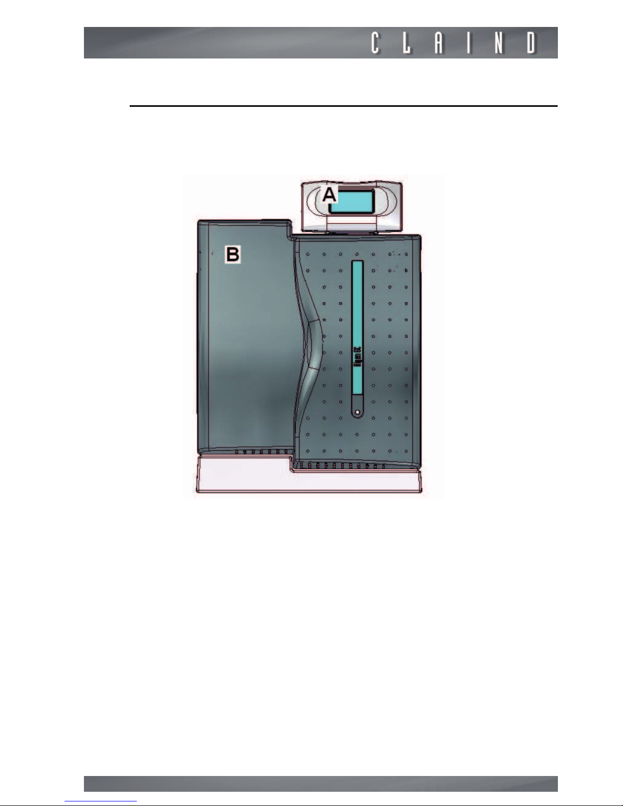
Claind NiGen GC User manual

User’s Manual
Nitrogen
Generator
NiGen GC
Nigen MICRO

2
Table of contents
1. Introduction 3
2. Safety 4
3. Description of the generator 6
4. Installation 11
5. Disasse bly and transport 16
6. Use 17
7. Maintenance 27
8. Troubleshooting 28
9. Guarantee 32
10. Declaration of confor ity 33
11. Notes 34

Nitrogen Generator NiGen GC Nigen MICRO
3
1.
Introduction
This docu ent is intended for users of nitrogen generator odels NiGen GC and
NiGen MICRO, and provides all infor ation regarding installation, use , ainte-
nance and guarantee.
The generator is intended to be used as a source of nitrogen gas for laboratory
applications, including gas chro atography, ther al analysis, ELSD, LCMS, sa -
ple preparation, etc.
The anual covers the following odels:
As regards installation and aintenance, it is assu ed that the user is fa iliar
with pneu atic circuit co ponents, and in particular is aware of the safety as-
pects of co pressed air and nitrogen.
The argin of the text contains the following sy bols, indicating:
m
compulsory safety standards to be observed
c
electrical hazard
e
reco endations and i portant infor ation
It is strongly reco ended to carefully read all safety warnings (
par. 2.1.
) be-
fore carrying out any operation on the generator.
Serial number Model
422.02.0110 NiGen GC
422.02.0220 NiGen GC HC 115 V AC
422.02.0230 NiGen GC HC 230 V AC
422.02.0510 NiGen MICRO

Safety
4
2.
Safety
e
The unit ust be installed and used in observance of the instructions in this boo-
klet. Further ore, use of the generator ust be li ited to that described in
Chapter 1 Introduction
. Failure to observe the foregoing will render the guaran-
tee null and void and release CLAIND fro all liability for direct or indirect da-
age or physical injury.
e
The user is responsible for asking local authorities if there are local safety regu-
lations that are stricter than what is described in this anual.
2.1.
arnings
m
Place the generators FAR FROM SOURCES OF HEAT
m
Place the generators in an environment PROTECTED AGAINST RAIN
AND IND
c
NEVER OPEN the generator while it is connected to the electrical
mains: RISK OF FATAL INJURY BY ELECTROCUTION
e
Repairs and inspections ust be carried out exclusively by QUALIFIED PER-
SONNEL: in the event of faults which cannot be resolved according to the pro-
cedures listed in the TROUBLESHOOTING chapter, contact exclusively our
authorized Technical Assistance.
e
If the generator is not to be used for a prolonged period of ti e, it ust be de-
pressurised (par. 6.7. and par. 6.8.).

Nitrogen Generator NiGen GC Nigen MICRO
5
2.2.
Notes on the use of nitrogen
Nitrogen is not a toxic gas, but when the percentage in the air exceeds specific
values there is a risk of asphyxia.
Therefore NEVER DIRECTLY INHALE the gas produced and avoid working in the
vicinity of a flow of nitrogen.
However, given the low quantities produced, it is sufficient that the flow of ni-
trogen occurs in a nor ally ventilated environ ent to avoid the risk of accu u-
lation.
m
If the generator and the user utility are located in different rooms, the
following minimum ventilation must be provided to prevent increasing
or decreasing the oxygen content in the air:
2.3.
Safety devices
MAXIMUM PRESSURE: the control syste constantly onitors the pressure.
In case of ano alous pressure, a safety valve (which operates independently of
the control syste ) prevents it exceeding 10.5 bar (152 psi).
MAXIMUM TEMPERATURE (
HC version only
): the purifier is fitted with an
internal catalyser, the te perature of which is constantly aintained at 420°C
To guarantee safety, a co pletely independent device is fitted which shuts off
power supply to the heating ele ent when te perature values exceed 480°C
2.4.
Technical assistance
The CLAIND technical assistance can be contacted as follows:
Phone ++39 0344 56603
Fax ++39 0344 56627
E ail: service@claind.it
Website: filling the for on the website www.claind.it at the “Service” section
Model Minimum generator
room ventilation
Minimum point-of-use
room ventilation
NiGen GC
NiGen GC HC
9 N 3/h
318 SCFH
16 N 3/h
565 SCFH
NiGen MICRO 3 N 3/h
106 SCFH
5 N 3/h
177 SCFH

Description of the generator
6
3.
Description of the generator
3.1.
Equipment supplied
Unless otherwise agreed, the consign ent includes:
• n°1 nitrogen generator odel NiGen;
• n°1 CD user’s anual;
• n°1 applicable declarations of confor ity of tank and safety valve;
• n°1 cable for the electrical ains;
• n°4 self-tapping screws;
• n°2 elastic spline;
• n°2 check pin;
• n°1 anchor plate;
• n°2 fitting for the connection of the plastic tube external dia eter 6 ;
• n°1 fitting for the connection of the copper tube external dia eter 1/8”.
3.2.
Technical specifications
3.2.1.
Nitrogen
(*) the flow rate is given at 20°C and 1 at
(**) purity referred to residual oxygen
Maximum flow rate (*)
NiGen GC 0.5 Nl/ in 0.5 slp
NiGen GC HC 0.5 Nl/ in 0.5 slp
NiGen MICRO 4 Nl/ in 4 slp
Pressure settable fro 0 to
6 bar
settable fro 0 to
87 psi
Purity (**)
NiGen GC up to 99.999 %
NiGen GC HC up to 99.999 %
NiGen MICRO up to 99.5 %

Nitrogen Generator NiGen GC Nigen MICRO
7
3.2.2.
Co pressed air supply, specifications
(***) for further details on the air quality, see the specifications for Class 1-4-1,
ISO 8573-1
3.2.3.
Electrical require ents
3.2.4.
Pneu atic connections
3.2.5.
Electrical connections
Pressure
ini u 8 bar 116 psi
axi u 10 bar 145 psi
Capacity
NiGen GC 6 Nl/ in 6 slp
NiGen GC HC 6 Nl/ in 6 slp
NiGen MICRO 12 Nl/ in 12 slp
Particulates: axi u concentra-
tion of particles of dia eter less
than 0.1 µ (***)
less than 0.1 g/ ³
Oil concentration less than 0.01 g/ ³
Humidity dewpoint under pressure less than 3°C
NiGen GC 115-230 V~ (±10%), 1 ph, 50-60Hz;
50W
NiGen GC HC
115 V~ (±10%); 60Hz; 1ph; 200W
or
230 V~ (±10%) 50Hz; 1 ph; 200W
NiGen MICRO 115-230 V~ (±10%), 1 ph, 50-60Hz;
50W
Nitrogen outlet G 1/8" fe ale
Compressed air supply G 1/8" fe ale
Power supply IEC320
CAN bus IN; CAN bus OUT RJ45

Description of the generator
8
3.2.6.
Di ensions
3.2.7.
Environ ental require ents
3.2.8.
Noise
idth 38 c 14.9”
Depth 53 c 20.8”
Height 47c 15.8” + 2.8”
eight
NiGen GC
NiGen MICRO
37 kg 82 lbs
eight
NiGen GC HC 41 kg 90 lbs
Installation site enclosed, indoors
Relative humidity up to 90%, no condensation
Use temperature fro 5°C to 40°C fro 40°F to
100°F
Protection rating IP20
Noise level at 1 meter 60 dB(A)

Nitrogen Generator NiGen GC Nigen MICRO
9
3.3.
Generator components
3.3.1.
Front view
A. CPU: generator control unit; it is the user interface by way of the touch screen;
B. FRONT PANEL, re ovable for aintenance operations.
FIGURE 3.3.1: Front view

Description of the generator
10
3.4.
Rear view
C. AIR INLET: pneu atic connection for co pressed air line inlet.
D. NITROGEN OUTLET: pneu atic connection for the generator’s nitrogen
delivery.
E. PRESSURE REGULATOR nitrogen delivery
F. CONNECTOR for electric power supply cable
G. POWER" KEY: ON-OFF switch; includes housing for the ain fuse
H. CAN BUS IN for connection to CPU
I. IDENTIFICATION LABEL: states the odel, serial nu ber (SN) and electrical
specifications
J. VENTILATION GRILLE
K. CAN BUS OUT
L. CAN BUS ADDRESS (DIP switch)
FIGURE 3.3.2. Rear view

Nitrogen Generator NiGen GC Nigen MICRO
11
4.
Installation
4.1.
Installation area requirements
4.1.1.
Environ ent
The area where the generator is installed ust eet the require ents listed un-
der
par. 3.2.7.
m
in particular, check if ventilation is adequate. Do not install the gene-
rator into a closed cabinet with insufficient ventilation.
In regards to ventilation, refer to
par. 2.2.
4.2.
Generator positioning
4.2.1.
Packaging re oval
• Open the packaging fro the top
• re ove the box containing the accessories
• lift the generator by grasping its side handles (two people are needed for this
operation) and set it o entarily on a flat surface
• re ove the support base and place it on the desk where you plan to install the
generator.
e
It is reco ended to store the packaging to ensure adequate protection when
oved in the future.
If the generator is to be installed on the tower see the attached.
4.2.2.
Positioning
Position the generator on its support base (two people are needed for this ope-
ration).
m
Ensure a clearance of at least 20cm at the rear of the generator. There
must be no potential sources of sparks in this clearance at the rear of
the generator, such as: flames, electrical contacts, hot surfaces, mo-
ving parts that can generate sparks, etc.
m
To not decrease ventilation efficiency, also ensure a clearance of at le-
ast 20cm at the front of the generator.
The generatore ust be positioned on the apposite base, following foregoing in-
structions:
• place the base in the installation site (you can adjust the plastic feet to the de-
sired height);

Installation
12
• position the generator on the base paying attention that the location respect the
height decrease of it;
• fasten the generator to the base (on the rear) using the screws and the anchor
plate included in the supply;
• re ove the front panel and insert the check pline in the apposite holes;
• the generator shall protrude of al ost 20 c so that the linchpins can be blocked
by elastic splines.
4.3.
Pneumatic connections
4.3.1.
Air inlet
m
The compressed air supply to the generator may not exceed 10.5 bar
(152 psi).
CONNECTION
• Locate the co pressed air inlet, arked “AIR INLET” at the rear of the genera-
tor;
• take fitting (1,2) and ount it;
• connect the line.
1
2

Nitrogen Generator NiGen GC Nigen MICRO
13
4.4.
Nitrogen outlet
m
The distribution line must be made of pipe rated for a pressure of at
least 10.5 bar (152 psi).
The pipe dia eter ust be sized on the basis of the acceptable pressure drop
values of the utility.
e
To ensure no inal purity of the delivered gas is aintained ( ini ize conta i-
nation fro oil residue, dust, scaling and hu idity), it is reco ended to use
clean and/or treated etal pipelines for final gas distribution.
CONNECTION
• Locate the nitrogen coupling, arked “NITROGEN OUTLET” at the rear of the
generator;
• take fitting (3) and ount it;
• connect the line.
3

Installation
14
4.5.
CPU connection
• Position the CPU where it will be used, e.g. above the generator, using the sup-
plied support;
• connect the ethernet cable to the rear of the CPU (top connector);
• connect the ethernet cable to the rear of the generator (CAN BUS IN connector);

Nitrogen Generator NiGen GC Nigen MICRO
15
e
Additional infor ation about the co unication connections can be found in the
Stack User’s anual.
The generator can works without CPU.
4.6.
Electric power supply
c
For reasons of safety, the following instructions must be strictly ob-
served.
The electrical installation ust co ply with current standards, in particular re-
garding the protection line/ground wire.
c
Recommendations for correct installation:
• do not use extension leads, adaptors or ultiple sockets;
• always connect the protection/ground wire;
• the ains socket and switch ust be located in an easily accessible position.
• if the provided power cable does not atch the local plug configuration, the
proper power cable with the appropriate configuration ust be obtained prior to
atte pting to apply power to the unit.
CONNECTION
• Locate the power cable connector (1) at the botto left side of the generator;
• before connecting the cable, ensure that the POWER switch is set to OFF;
• connect the power cable supplied with the generator.
1

Disassembly and transport
16
4.7.
arnings
e
If a failure in gas supply (due to a power failure, activation of an electrical safety
device, or generator fault), even te porary, is not ad issible, a pneu atic panel
should be envisaged, to enable provisional activation of a reserve gas source (to-
tally or partially auto atic).
4.8.
Packaging disposal
It is reco ended to store the original packaging to ensure adequate protection
for the purifier when oved in the future.
5.
Disassembly and transport
5.1.
Disassembly
• Stop the generator
(par. 6.7.);
• wait for depressurization (about a inute);
• switch off the generator
(par. 6.8.);
• disconnect the electric power cable;
• close all valves (air inlet, tanks) and detach the pneu atic connections.
5.2.
Transport
e
Re e ber that during transport the generator ust always re ain in a vertical
position.
If conserved, use the original packaging; otherwise use a pallet of adequate di-
ensions to hold the generator, affixing instructions in visible locations, such as:
THIS WAY UP, KEEP IN VERTICAL POSITION.

Nitrogen Generator NiGen GC Nigen MICRO
17
6.
Use
6.1.
Operator interface
TOUCH SCREEN
The CPU screen enables the user to interact with the generator, i.e. give specific
co ands or display and set para eters.
The table shows the function of the various keys on the screen:
Key Function
CPU access to CPU enu
PREVIOUS go to previous page
NEXT go to following page
ALARM access to list of alar s
WARNING access to list of warnings
RESET reset of alar s and warnings
MAINTENANCE go to aintenance request description
MENU access to different enus
ESC exit fro enu

Use
18
e
do not press on the touch screen with sharp objects
START start the production of gas
STOP stop the production of gas
INCREASE increase the value
DECREASE decrease the value
ADD add one digit
DELETE delete last digit
OK confir s odified value
Key Function

Nitrogen Generator NiGen GC Nigen MICRO
19
6.2.
Menus
The following chart shows the accessible enus for the operator:

Use
20
6.3.
LED warning light
In addition to the infor ation on the CPU screen, a LED warning light on the
front panel
(par. 3.3.1.)
indicates the operating condition of the generator.
The LED is yellow in the READY TO START condition.
The LED is green in the PRODUCTION condition.
The LED is flashing red in case of an error condition
(par. 8.4.).
6.4.
Initial start-up
1. Check that all connections are ade as specified in
par. 4.1. Installation area
require ents
2. close the nitrogen line downline of the generator
3. switch on the generator, by setting the POWER switch to ON (see
par. 6.5.
Generator start-up
)
4. start nitrogen production by pressing the START key (see
par. 6.6. Nitrogen
production
)
5. wait approxi ately 15 inutes, until the generator reaches the Stand-By
status. In this state, the generator suspends nor al production, showing the
following page:
6. fro this point the nitrogen is available for the line, by opening the valve closed
in point 2.
e
For the odel NiGen GC HC, it is suggested to supply gas to the application only
when the catalyzer has reached the operating te perature (approx 45 inutes
after switch ON)
e
WARNING: On initial start-up, the internal nitrogen storage tank will initially con-
tain air. For this reason, the line should be vented with the gas (for approx. 60
inutes) before e ploying the nitrogen for the application utility.
This manual suits for next models
2
Table of contents
Popular Inverter manuals by other brands

Hoymiles
Hoymiles HMT-2250/1800-6T Quick installation guide

PanelClaw
PanelClaw Polar Bear East/West 10 Degree installation manual

Stinger
Stinger SPI 160 instruction manual

YASKAWA
YASKAWA VS mini C Series instruction manual

Kaco
Kaco Powador 10.0 TL3 operating instructions

Growatt
Growatt Growatt 2500MTL-S Operation manual