SECURITY MANUAL FOR
C350, C400 and C700
10 / 12
Via Ugo Foscolo, 20
36030 - CALDOGNO - VICENZA - ITALY
Safety Manual for C350, C400 and C700 inverters 11/06/2018 Rev.2
4.2 Latency and reset times of the STO function
The latency time of the STO function of the inverter is the time that elapses between the opening
of the safety contact and the actual interruption of the PWM modulation to the IGBTs of the
inverter, i.e. the shutdown of the IGBTs.
When the IGBT is switched off, dangerous voltage is still present on all power
terminals of the inverter!
In Rowan inverters, the latency time does not exceed 10ms for all power sizes.
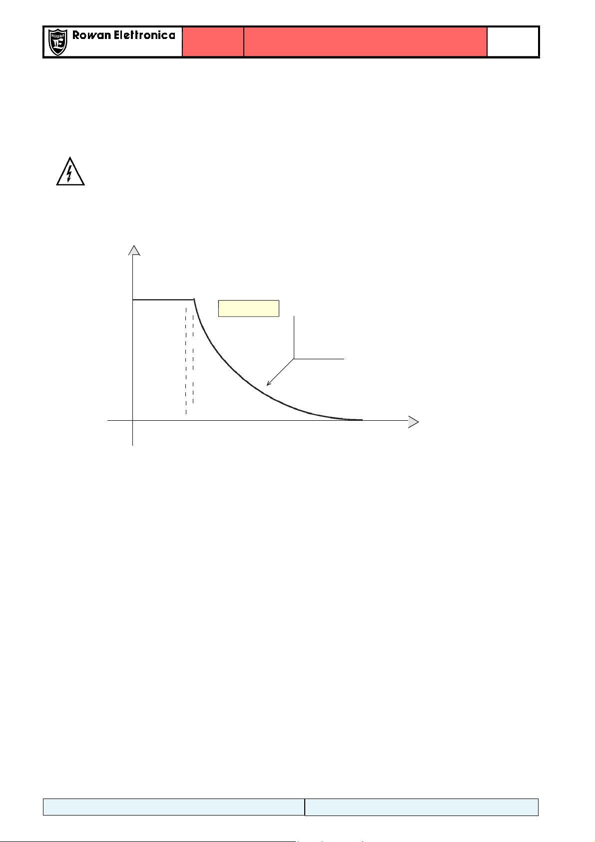
Figure 7 shows a graphic representation showing the engine speed - as a function of time -
around the time when the STO safety function is activated.
Engine
speed
T0 time of activation of the STO function.
T1 The moment when the engine cannot generate torque.
T = (T - T0): latency time of the STO function.
Fig.7: graphic example of v(t) trend with STO request.
The reset time, i.e. the time elapsing between the reclosing of the STO safety contact and the
actual PWM modulation at the IGBTs, depends on the system with which the plant controls the
inverter and the functions active in the inverter (e.g. on-the-fly recovery).
The reclosing of the safety switch can guarantee - after a certain time - the PWM to the IGBTs if
the run commands (RUN) have remained active.
Refer to the "Installation and Use Manuals" of the inverters and the following paragraph for the
evaluation of the run-up times.
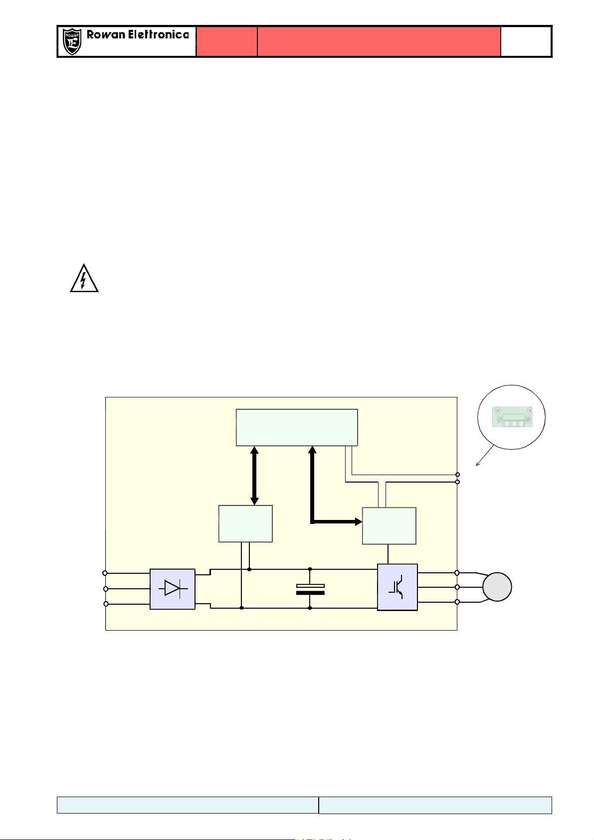
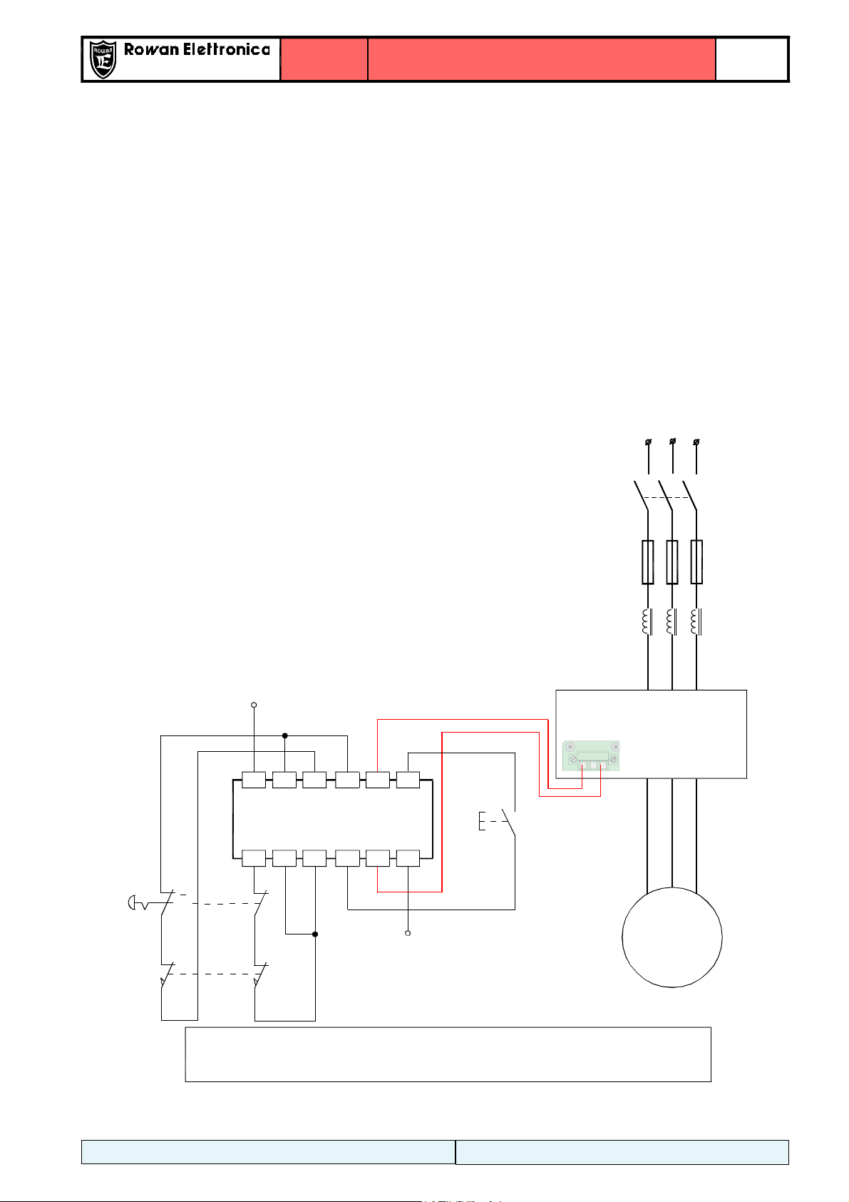
5POWER FAILURE DETECTION IN THE DRIVER SECTION
The C350, C400 and C700 series inverters implement a power failure detection system at the
inverter driver section; this interruption can also be achieved through a safety device or module.
This detection system cannot be part of the safety concept of the machine in which it is used, the
user can NOT consider it a fully-fledged system and useful for safety.
When the contact leading the power to the driver section is open, the inverter signals the event
with an alarm as follows:
-the FAULT led starts flashing;
-in C350 inverters, alarm number 106 is reported in the variable "6.27 ALARM";
-in C400/C700 inverters, the variable "2.1.50 INVERTER ALARM" shows the string STO OPEN;
-if the gear (RUN) was active before, it is now inhibited.
t
T 10ms
After T1 the engine is free
to rotate according to its
own inertia and its load.
Depending on the
application, it may be
necessary to use a
mechanical brake.
T T
0 1