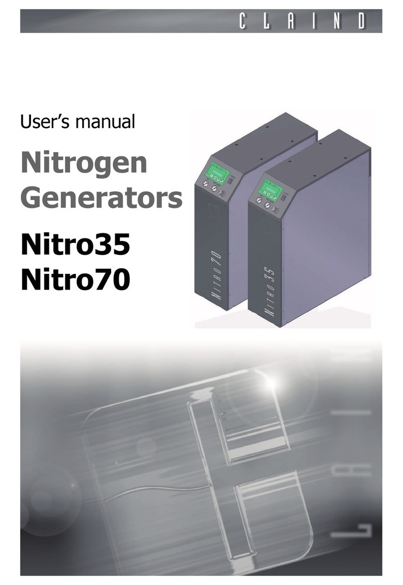
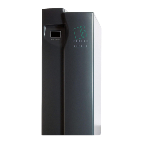
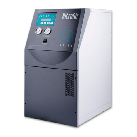
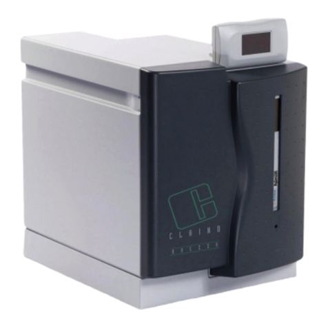
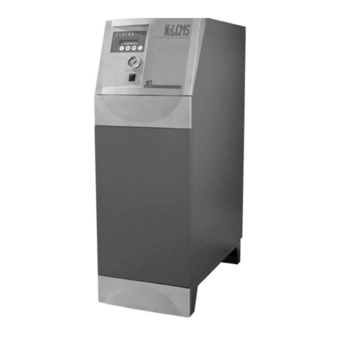
Claind NitroAir User manual

User’s manual
Nitrogen
and pure air
generator
NitroAir

2
Table of contents
1. Introduction 3
2. Safety 4
3. Description of the generator 6
4. Installation 9
. Disassembly and transport 13
6. Use 14
7. Maintenance 20
8. Troubleshooting 23
9. Guarantee 2
10. Declaration of conformity 26
11. Notes 27

Nitrogen and pure air generator NitroAir
3
1.
Introduction
This document si addressed to the user of a Nitrogen and pure air generator
mod. NitroAir and contains information concerning the installation, the use, the
maintenance and the warranty of the instrument.
As per the installation and maintenance operation, we assume that the user of
this Manual is experienced in the use of pneumatic components and, in particu-
lar, he is familiar with the safety issues regarding the use of compressed air.
The following symbols in the margin of the text indicate:
m
the mandatory safety rules
c
an electric shock hazard
e
important advices and information.
We recommend in particular to read carefully the safety warnings (par. 2.1.) be-
fore of performing any operation on the generator.

Safety
4
2.
Safety
This generator can be installed in close proximity to the utilization without clas-
sifying the surrounding area as “dangerous”, because it is designed with all the
necessary precautions in order to guarantee maximum safety.
The instrument must be installed and used following the instruction of this Ma-
nual. Failure in following the foregoing will render the warranty null and void.
Claind disclaims any responsibility for damages to people or property resulting
from improper use, from modifications or repairs carried out by unauthorised
personnel or if the instructions of this booklet are not followed.
2.1.
Warnings
m
The generator must be positioned FAR FRO HEAT SOURCES.
The generator must be positioned in a environnement SHIELDED FROM RAIN
AND WIND.
c
It is strictly forbidden to OPEN the generator when it is connected to
the power supply: FATAL ELECTROCUTION HAZARD
e
Repairs and controls must be performed only by SPECIALIZED TECHNI-
CIANS: for any problem not solvable following the indications listed in the chap-
ter FAILURE DETECTION, please contact exclusively CLAIND technical service.
e
Should the generator not been operative for a long time, it has to be convenien-
tly depressurized (see par. 6. .)
2.2.
Considerations about use of Nitrogen
Nitrogen isn’t a toxic gas, but when the percentual in a closed environment as a
room exceed certain values, suffocation hazard may occur.
We recommend therefore to NOT INHALE directly the outlet gas and to not work
in close proximity of the Nitrogen flow.
It is anyway sufficient a normally ventilated room to prevent accumulation risks,
since the flow of the Nitrogen generator is really small.

Nitrogen and pure air generator NitroAir
2.3.
Safety devices
m
AXI U PRESSURE:
Never apply pressure on the gas outlets: risk of damaging the generator. More-
over, an applied pressure superior to 10 bar, will lead to explosion hazard due
to the structural failure of the components.
2.4.
Technical assistance
e
CLAIND disclaims any responsibility resulting from improper use of the genera-
tor.
Before of performing any intervention it is necessary to contact CLAIND technical
service.
CLAIND technical service contacts:
Ph. ++39 0344 6603
Fax ++39 0344 6627
e-mail: service@claind.it

Description of the generator
6
3.
Description of the generator
3.1.
Supply
If not differently agreed, the supply includes:
• n°1 Nitrogen and Pure Air generator model NitroAir;
• n°1 certifications of the built-in reservoir and safety valves of the generator;
• n°1 power supply cable with Schuko plug;
• n°2 swagelok connectors 1/8” male for copper tube (external diameter 1/8”);
• n°4 nut 1/8” Swagelok;
• n°4 back ferrule Swagelok 1/8”;
• n°4 front ferrule Swagelok 1/8”;
• n°1 tube plastic connector (external diameter=4mm) with drain silencer;
• n°1 CD user’s manual;
• n°4 plastic caps for the top panel.

Nitrogen and pure air generator NitroAir
7
3.2.
Specification
3.2.1.
General
3.2.2.
Electric
3.2.3.
Gas
The flow rate and the purity degree of the outlet air and Nitrogen vary with the
kind of utilization and of application. The data of the present model are indicated
on the related product sheet.
Dimensions Lenght 40 cm
Width 3 cm
Height 83 cm
Weight 78 kg
Dimensioni imballo Lenght 0 cm
Width 64 cm
Height 10 cm
Gross weight 86 kg
Noise level (1m far from the front
panel) 7 dB(A)
Working Temperature tra °C e 3 °C
Protection IP20
Power supply 230 V~ (±10%); 1ph; 0Hz
Adsorbed power 7 0 W

Description of the generator
8
3.3.
Elements of the generator
3.3.1.
Front view
3.3.2.
Rear view
A. ALPHANUMERIC DISPLAY AND
KEYPAD: indicates the operative or
alarm condition; the four keys allows
to display and to set the working
parameters.
B. NITROGEN GAUGE: indicates the
pressure in the outlet Nitrogen line.
C. AIR GAUGE: indicates the pure air
outlet line pressure.
D. “POWER” KEY: is the power switch.
A. AIR PRESSURE REGULATOR: is
needed to regulate the output
pressure of pure air.
B. CONNECTOR for the power cable; it
includes the slot for the main FUSE,
whose specification are listed on the
“B” label.
C. N2 PRESSURE REGULATOR: is
needed to regulate the Nitrogen outlet
pressure.
D. LABEL: shows the identificative data
of the generator, the power supply
data, and the EC marking.
E. DRAIN: pneumatic connector for
condensation drain.
F. AIR: pneumatic connector for the
pure air vent.
G. NITROGEN: pneumatic connector for
Nitrogen vent.
D
C
A
B
A
B
C D E F G

Nitrogen and pure air generator NitroAir
9
4.
Installation
4.1.
Installation area requirements
4.1.1.
Moisture and particulate
In order to avoid any risk of damages to the electronic component, it is recom-
mended to install the generator in a environment where relative moisture and
particulate concentration are limited.
Moreover, the generator must be protected from dripping, rain and wind.
4.1.2.
Temperature
The temperature of the environment where the genertor is installed must be
between °C and 3 °C.
Please avoid proximity to heat sources and exposition to sunlight beams.
4.2.
Positioning of the generator
4.2.1.
Handling
The packed generator can be handled using suitable equipments, such as a
“transpallet” or a forklift truck. Once unpacked, it can be moved by its own whe-
els.
e
The generator must always stand in vertical position, because it hasn’t been de-
signed to be layed.
4.2.2.
Packing removal
The generator is delivered on a dedicated pallet.
Remove packing, paying attention to not damaging the panels of the generator.
The generator must be lifted from the pallet using dedicated equipment or even
manually by at least 4 people.
If possible, conserve the original packing to guarantee adequate protection to
the instrument in case of future handling.
4.2.3.
Compressor block removal
e
Before of the generator start-up, remove the compressor block. Failure in per-
forming this operation will damage or break the generator.

Installation
10
Following the procedure to re-
move the compressor block:
1. Unfasten the rear bottom panel.
2. Disconnect the fan cable and
the ground cable.
3. Detect the right angled profile
(in red) that blocks the
compressor on the base of the
generator.
4. Unfasten the screws that block
it to the base (2).
5. Unfasten the screws that block
it to the compressor (1).
6. Remove the right angled
profile.
7. Fasten the screws to the
compressor(1).
8. Position the right
angled prifle on
the base of the
compressor in
correspondence of
the holes for the
blocking of the
screws.
9. Position the
screws (2).
10. Push the right
angled profile
toward the
generator (A).
11. Fasten the screws
(2).
12. Gently shake the
compressor to verify that it is free to move on the rubber feet and that it
doesn’t collide with the compressor block right angled profile.
13. Connect again the fan and the ground cable.
14. Fasten againg the rear lower panel.
The right angled profile must be mounted again in the correct way in case of
future handling.
A
2
2
1
1

Nitrogen and pure air generator NitroAir
11
4.2.4.
Cap application
Apply the four caps include in the supply on the four holes on the top panel .
4.3.
Pneumatic connections
The fittings for the connection are located on the rear of the generator and are
of the automatic type.
The supply includes two kinds of connectors; one to perform the connection with
the 1/8” copper tube for pure aire and Nitrogen (A) and the other one to connect
the silencer to the drain with a 4 tube (B).
The generator is delivered with the vent of the air and of Nitrogen closed by a
cap, that obviously has to be removed before of performing the connection.
A
B

Installation
12
4.4.
Power supply
c
For your safety it is mandatory to comply with following prescriptions.
Electric installation must comply with the law in force, particularly with the regu-
lation on the protection line.
c
Advices for a correct installation:
• do not use extension cable, adaptor or multiple socket; when necessary, substi-
tute the Schuko plug with another adequate one.
• Always connect the protection conductor;
• the power socket has to be located in a easily accessible place.
CONNECTION
• Locate the fitting for the connection of the power cable on the rear of the gen-
rator.
• Before of connecting the cable, verify that the POWER switch is in OFF position.
• Connect the power supply cable (2m lenght, Schuko plug IEC320 C13)
4. .
Warning
e
In case that even momentaneus failures in gas supply (due to interruption of the
power supply, the intervention of a power protection, a failure of the generator)
aren’t acceptable, it will be opportune to forecast a pneumatic switch board that
allows the temporary insert of a secondary gas source more or less automati-
cally.
e
As a precaution the restart of the generator after a interruption of the power
supply isn’t automatic, but manual on operator command.
e
In case that the automatic restart of the generator is necessary after a black-out
during the operation, it is necessary to set this modality in the set-up software.
4.6.
Disposal of the packing
It is recommedend to keep the original packing for possible future handling, as
it guarantees adequate protection to the generator.

Nitrogen and pure air generator NitroAir
13
.
Disassembly and transport
.1.
Uninstall
• Arrest the generator (see par. 6. .)
• Wait for depressurizzation
• Switch the generator off(see par. 6.6.).
• Disconnect power supply cable.
• Close all the valves on the air pipeline and disconnect the pneumatic connection.
.2.
Transport
e
Please remember that during trasport the generator must always stand in verti-
cal position.
Mount the right angled profile in the correct way so that the compressor is bloc-
ked.
1. Unfasten the rear panel.
2. Disconnect the fan cable and the ground cable.
3. See the right angled profile (in red).
4. Unfasten the screws (1) of the compressor.
5. Unfasten the screws (2) that block the right angled profile on the base of the
compressor.
6. Position the right angled profile so that the screws (1) are lodged in the holes.
7. Position the screws (2) .
8. Fasten the screws(1).
9. Fasten the screws(2).
10. Verify that the compresor is blocked in the correct way, shaking it gently. If the
right angled profile is correctly blocked, the compressor doesn’t move (see fig.
par 4.2.3)
11. Connect again the fan cable and the ground cable.
12. Fasten again the rear lower panel.
13. Position a sheet on the generator indicating that the blocks of the compressor is
mounted.
Reuse, if you have kept it, the original packing; if you haven’t, please realize a
new packing using a pallet of adequate dimensions, and applying very clear and
visible indications such as: KEEP IN VERTICAL POSITION, UP

Use
14
6.
Use
6.1.
Keypad and display
KEYPAD
Using the keypad on the front of the generator, the user can interract with the
generator, or give specific commands or display and set parameters.
The table shows the function of the different keys on the keypad.
DISPLAY
The display is made up of two lines of 20 characters each.
Usually the functions or parameters are displayed on the upper line, and the re-
lated status and values are displayed in the lower line.
Should the message exceed 20 characters, it can be slided.
Key Function
Function Selects a function of the generator
Cursor Increases the selected value
Cursor Decreases the selected value
Operative Starts or stops the generator

Nitrogen and pure air generator NitroAir
1
6.2.
First start-up
6.2.1.
Setting
The geneator is supplied pre-set and ready to start production. The user can ac-
cess to the set up of some parameters (such as language, start-up way, etc.).
See par. Parameters setting.
6.2.2.
Operative sequence
1. Verify that all the connection are performed according to what described in
Chapter 4 (INSTALLATION)
2. Switch the generator on, switching ON the POWER key (see par. 6.3. Start-up of
the generator).
3. Start the production of pure air pressing the START-STOP key.
4. Wait till the generator enters the stand-by condition. In this condition, the
generator interrupts the normal cycles of production and the display shows the
message: STAND-BY.
5. From this moment on, pure air is availble for the line.
6. Let it flow in ambient air for at least 30 minutes, in order to clean the reservoir
and the line.
6.3.
Start-up of the generator
To start-up the generator, switch the POWER key on the front panel ON.
The display lights up and, after some seconds, a depressurization cycle is auto-
matically started. During this phase, that lasts maximum 30 seconds, following
message is displayed:
PLEASE WAIT
UNDER DEPRESSURIZATION
When the depressurization is over, the following message
is displayed:
GENERATOR READY
In this condition, the generator is ready to accept the command of start-up of
the production (see par. 6.4.) or of switch off (see par. 6.6.).
6.4.
Air and Nitrogen production
When the generator has ended the preparation phase (par. 6.3.) and the display
shows the message
GENERATOR READY
, you can start air and Nitrogen
production, in the following way:

Use
16
Press operative key START/STOP.
The productive cycle is started-up and the following message appears: I
PRODUCTION
6. .
Stop of the generator
Any moment during production, it is possible to arrest the generator pressing the
START/STOP key.
During depressurization, that usually lasts 30-60 seconds, the following message
is displayed:
PLEASE WAIT
UNDER DEPRESSURIZATION
e
PLEASE NOTE: during an allarm block of production, the START/STOP key isn’t
operative.
At the end of depressurization, the following message appears:
GENERATOR READY
Now you have two alternatives:
1. switch the generator OFF using the POWER switch (see par. 6.6.);
2. restart production pressing the START/STOP key (see par. 6.4.).

Nitrogen and pure air generator NitroAir
17
6.6.
Switch off the generator
6.6.1.
Correct Switch Off
The correct way to switch off the generator starts from the condition of
GENE-
RATOR READY
.The par. 6. . describes how to reach that condition.
Switch the "POWER" key OFF to switch off the generator.
6.6.2.
Incorrect Switch Off
Avoid to switch off the generator without arresting it before following the in-
structions of par. 6. .
This may happen accidentally or in case of black-out. In this case, to the next
start-up of the generator the following message will appear:
WARNING
INCORRECT SWITCH OFF
To suppress the alarm, press function key .
6.7.
Display of parameters
6.7.1.
Display of the status of the generator
During production, the main page of the display shows the following message:
PRODUCTION
In order to have more information on the status of the generator, press the up
arrow key . The display will show the following page:
ZZZ YYY XXX
00,0 00,0 000
Where:
ZZZ
= status of the compressed air, in bar
YYY
= status of the nitrogen production, in bar
XXX
= status of the air production, in bar
The values are continuosly updated in order to verify the correct operation of the
generator
To exit from this page and to come back to the main page, press the down arrow
key .

Use
18
6.7.2.
Display of working hours
The generator is equipped with an hour counter of the compressor displaying
also the remaining working our of some components before of their substitution
in order to guarantee a correct maintenance.
To display the working hour, go to main page (
PRODUCTION
) and presse
once the down arrow key .
To exit from this page and come back to main page, press once up arrow key .
6.8.
Setting of the parameters
To access to these parameters you have to switch the generator on pressing for
some seconds the Function key .
The data will be sequenced as indicated in the table above.
To modify them, press the arrow keys .
To acquire the set value, press the up arrow key ; while pressing the function
key . With this operation you access also to the following parameter.
Finally, to quit the menu, press for some second the Function key .
6.8.1.
Editing maintenance parameters
See par. Maintenance.
Language of messages
Italian
English
German
French
Spanish
Restoration of the production after incorrect switch off
Manual
Automatic
Incorrect switch off alarm
Enabled
Disabled

Nitrogen and pure air generator NitroAir
19
6.8.2.
Setting the Minimum Air Pressure alarm
OUTPUT MINIMUM PRESSURE
xx.x bar
This value represents the minimum air pressure value in the built-in reservoir of
the generator, under which the alarm “UNSUFFICIENT AIR PRESSURE” is acti-
vated.
To access from the main menu press the Function key . This value can be in-
creased or decreased pressing the Function key and pressing the up arrow
key or down arrow key at the same time
To go back on main page, press for some second the Function key .
e
The default value is 6.0 bar.
6.8.3.
Regulation of the output air pressure
• The regulator is located on the rear of the generator (see par. 3.3.2).
• Rotate the control knob to regulate the pressure to the desired value (clockwise
to increase pressure), displaying it on the gauge (AIR) on the front panel of the
grenerator (see par. 3.3.1).
e
The default regulation is 0.0 bar (vent closed).
6.8.4.
Regulation of the minimum Nitrogen pressur alarm
To access to the parameter press the function key from the main menu.
MINIMUM OUTPUT PRESSURE
xx.x bar
This value represents the Nitrogen pressure on the internal tank under which the
alarm UNSUFFICIENT NITROGEN PRESSURE is activated.
To access from the main menu, press the function key . This value can be
increased or decreased by pressing the Function key while selecting the up
arrow key or the down arrow key .
To go back on the main page, press the function key f for some seconds.
e
The default value is 6.0 bar.
6.8. .
Nitrogen output pressure regulation
• The regulator is positioned on the rear of the generator (see par. 3.3.2).
• Rotate the control knob to regulate the pressure to the desired value (clockwise
to increase pressure), indicated by a gauge (NITROGEN) on the front of the in-
strument (see par. 3.3.1).
e
The default regulation is 0.0 bar (vent closed).

aintenance
20
7.
aintenance
The generator contains a list of components subject to wear and tear. In order
to guarantee an adequate programmed mainentance, for each one of these
components is set a working-time during testing phase.
During the operation, this time is decreased till its expiry and when it is over the
control board generates a maintenance request automatically.
7.1.
Deadline warnings
During production, when the forecasted autonomy of a components expires, a
message is diplayed, such as the example below:
WARNING
EXHAUSTING SILENCER
In order to acquire the warning please press function key . After that the
message disappears to proceed with normal operation.
At the next start-up, the generator asks if the maintenance operation has been
performed displaying the following message (referring to previous example):
SUBSTITUTION OF THE SILENCERS COMPLETED?
NO
Pressing up arrow key ” select “YES” or “NO” consequentely. After selecting
the reply, press the function key to acquire it.
If you reply “NO”, to next start-up, the message will be displayed again, while,
replying “YES”, the working time of the component will be reset (the one set up
at the beginning of count-down) for future maintenance.
Should the alarm of incorrect switch-off be present at start-up time, this proce-
dure isn’t activable: it will be anyway available to next start-up.
Other manuals for NitroAir
1
Other Claind Portable Generator manuals
Popular Portable Generator manuals by other brands

Champion
Champion 42451 Owner's manual & operating instructions

Powermate
Powermate Black Max PMC496500 user manual

ADJ
ADJ ACCU-CABLE POWER BONE T1ED user manual

Briggs & Stratton
Briggs & Stratton PowerBoss 030217 Wiring diagrams

King Canada
King Canada KCG-4500i instruction manual
Wen
Wen 56877 owner's manual
