Claind HyGen200 User manual
User’s manual
Hydrogen
generator
HyGen200
HyGen400
HyGen600

2
Summary
1. Introduction 3
2. Safety 4
3. Description of the generator 7
4. Demineralized ater 13
5. Operator interface 14
6. Use 19
7. Installation 28
8. First start up 38
9. Uninstalling and transport 45
10. Maintenance 50
11. Fault list 69
12. Warranty 75
13. Declaration of conformity 76
14. Notes 77

Hydrogen generator HyGen
3
1.
Introduction
This document is aimed at the user of a hydrogen generator model in the Hy-
Gen series and provides all the information regarding installation use and main-
tenance.
This manual is an integral part of the generator and as such is to be safeguarded
and must al ays accompany the appliance.
Make sure it is al ays consistent ith any updates implemented in the genera-
tor.
Please contact Claind directly in order to use and reproduce this documentation.
Claind is al ays at the disposal of users to provide clarification on the appropri-
ate use of the information.
The intended use of the generator is to produce (as an alternative to cylinders)
ultra-pure hydrogen gas for analytical laboratory applications.
The generators in the Hygen series are listed belo .
The margin of the text contains the follo ing symbols, indicating:
m
compulsory safety rules to be observed
c
electrical hazard
e
recommendations and important information
This manual describes only the operations that customers can perform, all other
operations (eg. maintenance of the circulation pump) must be performed by a
Claind specialized technician, other ise Claind shall not be held liable for any
damage caused to property, animals or people.
It is assumed that the manual user is experienced in the use of pneumatic com-
ponents, and in particular is a are of all safety aspects linked to the use of hy-
drogen.
You are urged to pay particular attention to the safety arnings (
par. 2.2 Warn-
ings
) before performing any ork on the generator
Code Description
422.01.0110 HyGen200 115/230V 50/60HZ
422.01.0210 HyGen400 115/230V 50/60HZ
422.01.0310 HyGen600 115/230V 50/60HZ

Safety
4
2.
Safety
e
The unit must be installed and used in observance of the instructions in this boo-
klet Furthermore, use of the generator must be limited to that described in
Chapter 1 Introduction.
Failure to observe the foregoing ill render the guaran-
tee null and void and release CLAIND from all liability for direct or indirect da-
mage or physical injury.
e
The user is responsible for asking local authorities if there are local safety regu-
lations that are stricter than hat is described in this manual.
The generator has been built follo ing the ackno ledged safety rules, ho ever,
incorrect use can be a source of danger to the life and safety of the user or
others or of damage to property.
e
Any non-compliance ith the safety instructions or arnings can cause fatal
injuries.
Use the generator only in perfect technical condition, respecting the safety ar-
nings. In the event of any trouble call the Claind service centre immediately
(Par.
2.5 Technical Assistance)
2.1. Improper se
e
Improper use of the generator ill void arranty. Claind shall not be held liable
for any damage caused to property, animals or people due to improper use of
the generator.
1. Never direct the gas issuing from the generator at people or animals.
2. If the generator is not to be used for a long time, unplug it from the mains.
3. Prohibit children and unauthorized personnel from using the generator.

Hydrogen generator HyGen
5
2.2. Warnings
m
Hydrogen forms FLAMMABLE MIXT RES WITH AIR when its percent-
age is greater than 4%. Therefore do not accumulate the gas: if nec-
essary, comply with the applicable current standards
m
Place the generator FAR FROM SO RCES OF HEAT, SO RCES OF IGNI-
TION AND FLAMES
m
The generator must work with its protective container: this ensures
proper air circulation and avoids the formation of pockets of gas.
m
Place the generator in an environment PROTECTED AGAINST RAIN
AND WIND
c
NEVER DISASSEMBLE the generator when it is connected to the elec-
tric mains: there a RISK OF DEATH from electric shock
e
For any issues that cannot be resolved by follo ing the procedures given in par.
11. troubleshooting, call solely CLAIND Technical Assistance. Repairs and in-
spections must be carried out exclusively by Q ALIFIED PERSONNEL
2.3. Safety rules
Failure to follo the safety rules can cause unpredictable danger, so it is strongly
recommended to pay special attention to the follo ing:
• Smoking and naked flames are strictly forbidden;
• do not deposit any flammable materials near the generator;
• ensure appropriate and sufficient lighting to read the arnings and carry out the
ork safely;
• set up appropriate extinguishers;
• observe the required environmental conditions
(par. 3.2.7. Environmental requi-
rements);

Safety
6
2.4. Safety devices
MAXIM M PRESS RE: The maximum operating pressure that can be set is 8
bar.
There is a double pressure control:
• one is a pressure sensor, via the control system, hich shuts do n the generator
hen pressure values exceed 0.5 bar (set value);
• a pressure s itch, independent of the control system, limits the pressure to 11
bar.
HYDROGEN-AIR MIXT RE: The formation of a potentially hazardous hydro-
gen-air mixture inside the generator is prevented by a forced ventilation system.
If the ventilation system fails to operate, a dedicated sensor makes the genera-
tor stop.
Any significant gas leaks are also indicated by the line pressure control system.
2.5. Technical Assistance
Before performing any type of operation you must contact CLAIND technical as-
sistance at the follo ing:
Tel. ++39 0344 56603
Fax ++39 0344 56627
e-mail: [email protected]

Hydrogen generator HyGen
7
3.
Description of the generator
3.1. Equipment supplied
Unless other ise agreed upon, the supply of a generator in the HyGen series
includes:
• No. 1 HyGen model hydrogen generator;
• No. 1 user manual CD.
• No. 1 cable for the electric mains;
• No. 1 Ethernet cable;
• No. 1 quick coupling elbo ;
• No. 1 copper pipe fitting ith outside diameter 1/8”;
• No. 2 fixing pins;
• No. 4 self-tapping scre s;
• No. 2 flexible tabs;
• No. 1 anchoring plate;
• No. 1 Allen rench size 8;
• No. 2 Resin bed;
• 5 m plastic pipe outside diameter 4mm;
• 2 m PVC pipe outside diameter 9mm.

Description of the generator
8
3.2. Technical specifications
3.2.1. Hydrogen
(*) by default it is set to 4 bar
3.2.2. Demineralized ater requirements
3.2.3. Electrical requirements
3.2.4. Pneumatic connections
Capacity
HyGen 200 up to 0.200 Nl/min
HyGen 400 up to 0.400 Nl/min
HyGen 600 up to 0.600 Nl/min
Pressure (*) settable from 2 to 8 bar
Consumption
HyGen 200 up to 0.4 fl oz/h
HyGen 400 up to 0.81 fl oz/h
HyGen 600 up to 1.22 fl oz/h
Temperature from 5°C to 35°C
Quality
required resistivity 1 M
Ω
cm @25°C ASTM Type II
Supply voltage 110-240 Vac; 50-60 Hz
Maximum power consumption
HyGen 200 110 W
HyGen 400 180 W
HyGen 600 250 W
Hydrogen output 1/8" BSPT male for copper pipe
Air vent automatic coupling for plastic pipe
diameter 4 mm

Hydrogen generator HyGen
9
3.2.5. Electrical connections
3.2.6. Dimensions
3.2.7. Environmental requirements
* = the air must be clean and free of harmful substances (eg. dust, fibres, sand)
3.2.8. Noise
Power supply Cable ith Schuko plug
CAN bus IN, CAN bus O T Ethernet cable ith RJ45 connector
Width 38 cm
Depth 53 cm
Height ( ith support base) 47 cm
Weight (generator only) 25 kg
Weight (including support base) 27 kg
Protection rating IP20
Installation site* indoor room, classified non-hazard-
ous
Minimum ventilation 4 Nm3/h
Maximum inclination ± 1°
Relative humidity up to 90%, no condensation
se temperature from 5°C to 35°C
Storage and transport temperature from 5°C to 40°C
Noise level at 1 metre < 50 dB(A)

Description of the generator
10
3.3. Generator components
3.3.1. Front vie
A. CPU: Generator interface via touch-screen display.
B. FRONT PANEL, removable for maintenance operations;
C. TANK LED (BACKLIGHTING): highlights the level of ater contained in the
reserve tank;
D. STATUS LED (INDICATOR LIGHT): indicates the operating condition of the
generator;
E. BASE for setting it on a bench.
A
B
D
E
C
Hydrogen generator HyGen
11
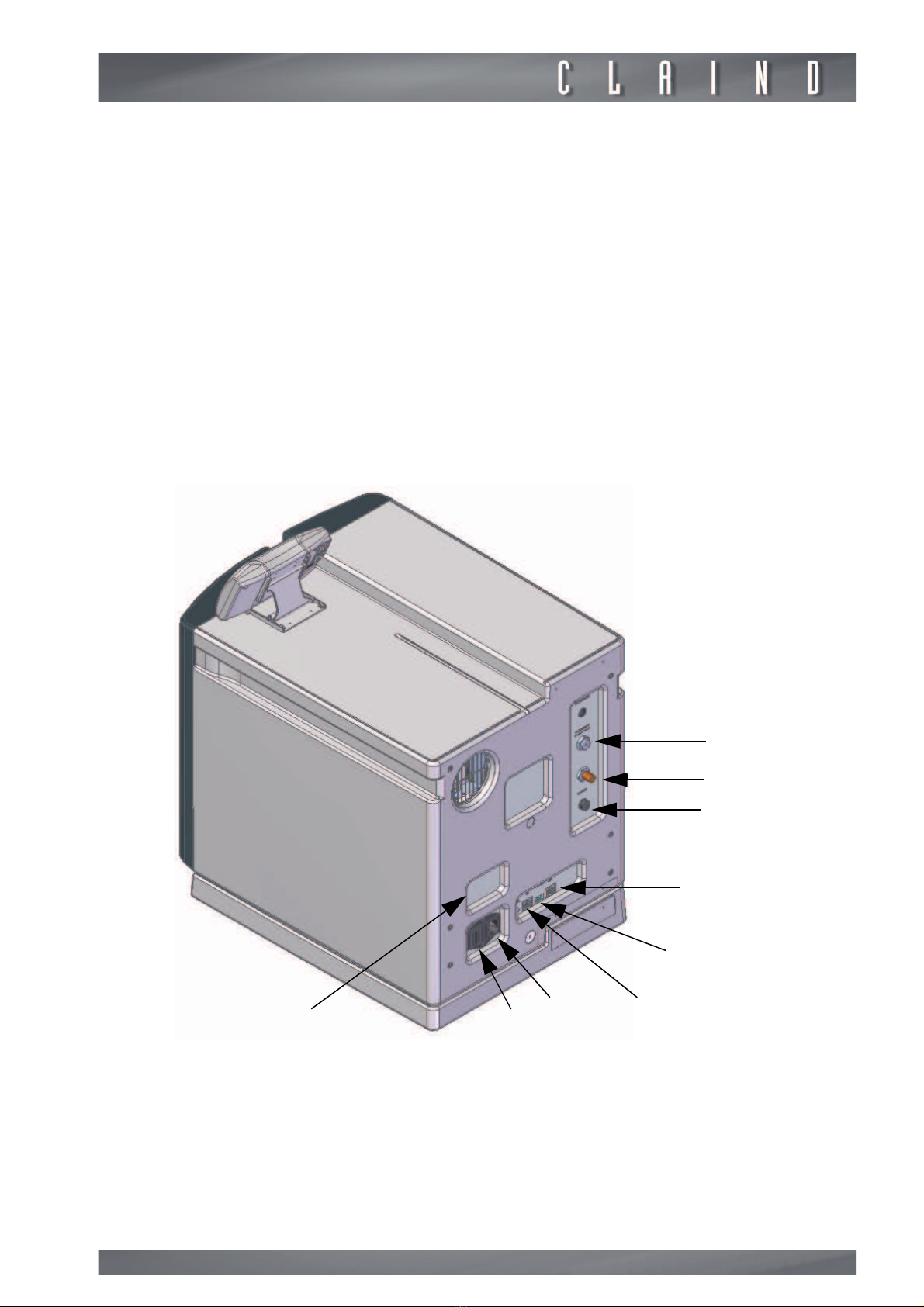
3.3.2. Rear vie
A. H2 DELIVERY: coupling for connecting the hydrogen line;
B. H2 VENT for venting at ambient pressure;
C. DRAIN: quick coupling for 4mm pipe connecting the condensate drain line;
D. CAN BUS OUT: connection to any other generator ith an Ethernet cable
(Breeze stack manual)
;
E. NETWORK ADDRESS: setting generator No. in net ork
(Breeze stack manual)
;
F. CAN BUS IN: connector for connecting to the CPU;
G. DRAIN: fitting for connecting the drain line should any ater come out from
the tanks;
H. CONNECTOR for the po er cord; includes housing for the main FUSE;
I. ON-OFF SWITCH;
J. IDENTIFICATION LABEL: states the model, serial number (SN) and electrical
specifications.
A
B
C
D
E
FH
JI
G
Description of the generator
12
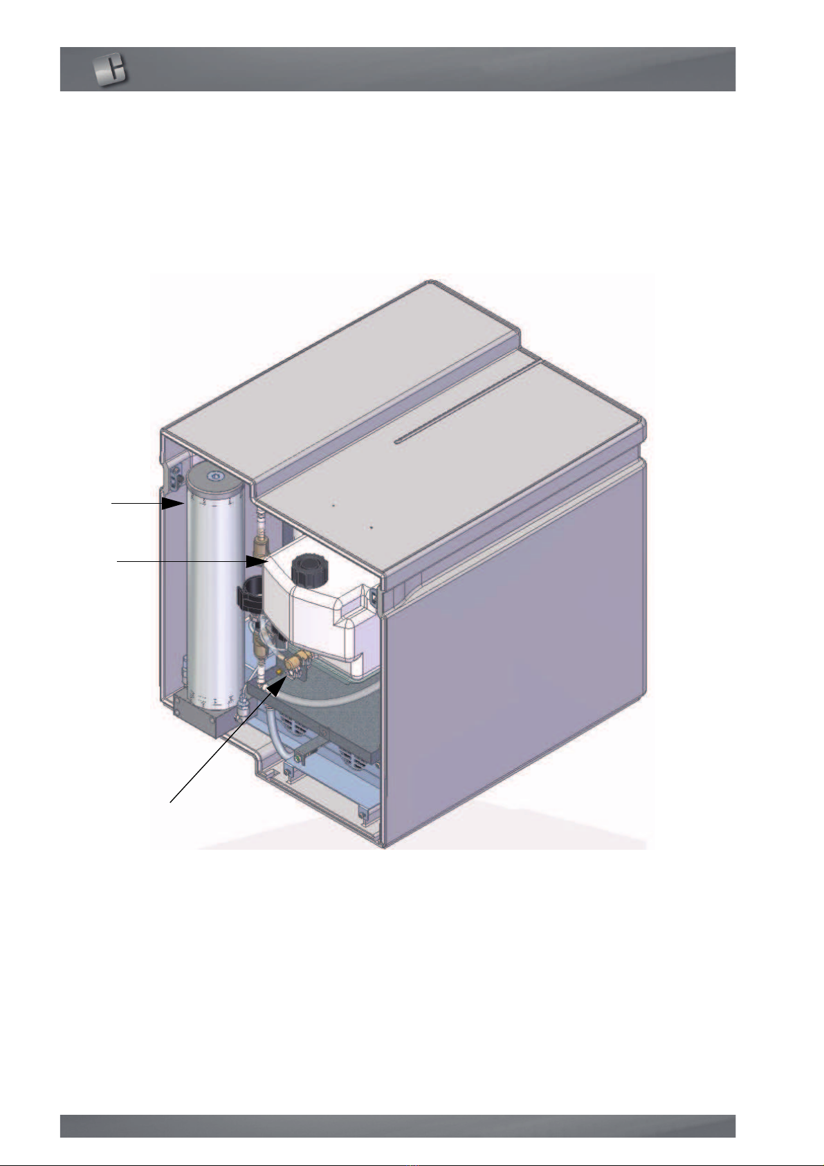
3.3.3. Internal vie
A. DRYER: pipe containing zeolite for drying the gas;
B. DEMINERALIZED WATER RESERVE TANK: tank that, hen full, guarantees
continuous independent operation of the generator for 3 days. The tank is
backlit for better vie ing of the ater level;
C. DEMINERALIZED WATER DRAIN: automatic fitting for the drain pipe.
A
B
C

Hydrogen generator HyGen
13
4.
Demineralized water
e
The range of the resistivity value displayed by the CPU is the follo ing:
0.5 - 1.5 M
Ωcm @25°C.
m
The use of inadequately demineralized water irreversibly ruins the
hydrogen generation cell.
e
CAUTION! Failure to comply ith the instructions contained in this manual ill
void the arranty.
The generator is equipped ith a system that detects hether the ater used
does not meet the required specifications, in hich case a arning signal ill be
emitted
(Par. 11.3. List of Warnings)
4.1. Production of demineralized water
The ater for the hydrogen generator must be adequately demineralized. It is
compulsory to use a professional demineralizer that can filter ater to values
1 M
Ωcm @25°C.
In order to ensure good demineralization, e recommend carefully follo ing the
demineralizer maintenance sheet.
Avoid storing demineralized ater for any longer than one month.
4.2. Bottles of demineralized water
A. The quality of the ater bought in bottles or containers must comply ith the
specifications contained in
par.3.2.2.
e
In particular, the resistivity must be 1 M
Ωcm @25°C.
B. look at the expiry date;
C. do not use the ater contained in containers that have been open for more
than a month: the risk that the ater has lost its characteristics is very high. It
is strongly recommended to buy small containers;
D. check before use that the resistivity of the ater meets the recommendation,
using a resistivity meter of hich you kno the uncertainty of measurement
(0.1 M
Ωcm @25°C)
;
E. remember to close the bottle carefully after use.
Operator interface
14
5.
Operator interface
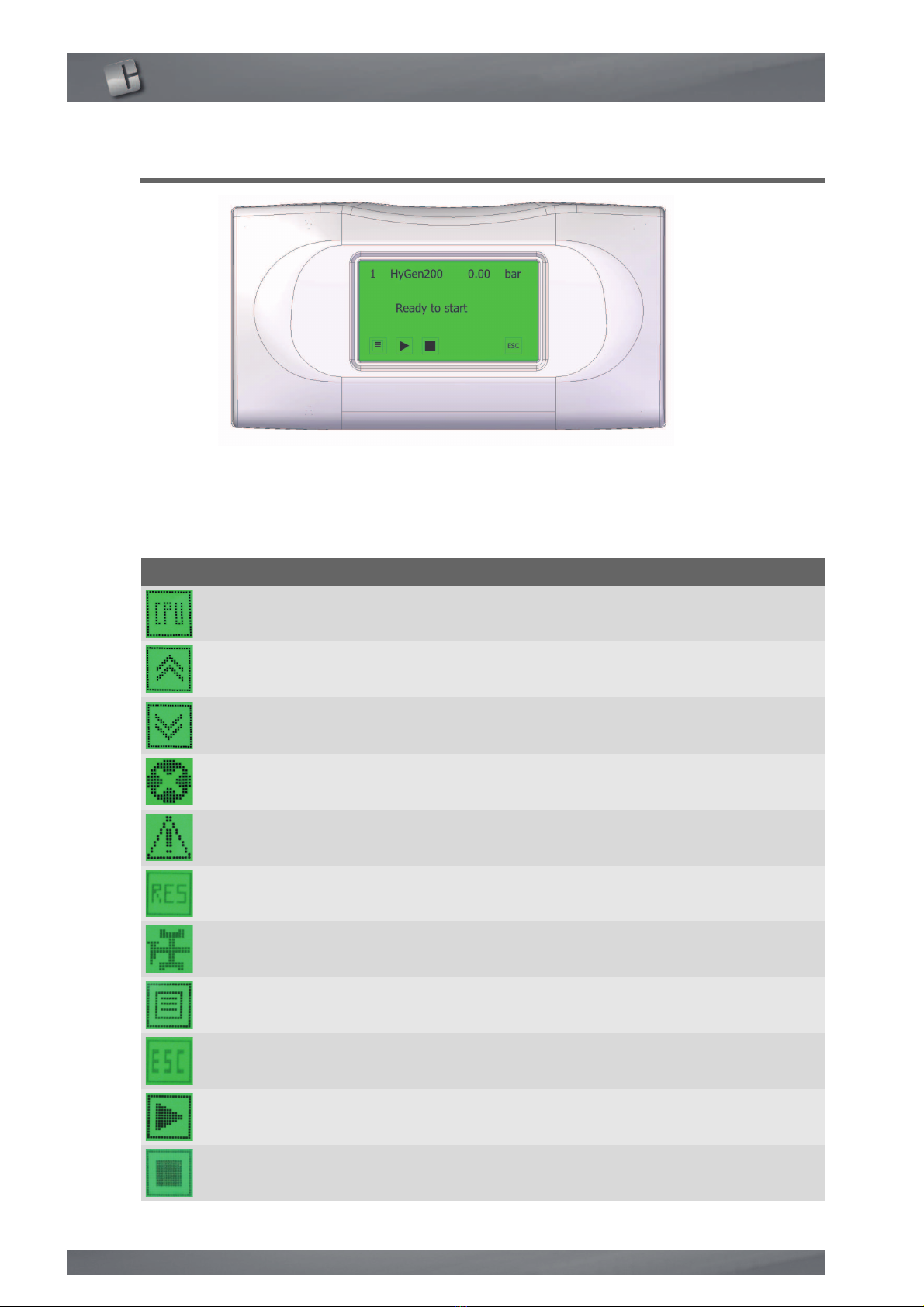
TO CH-SCREEN
The CPU screen enables the user to interact ith the generator, i.e. give specific
commands or display and set parameters.
The table sho s the function of the various buttons on the screen
Key Function
CPU access to the CPU menu
PREVIOUS goes back to the previous page
NEXT goes to the next page
ALARM access to the list of errors
WARNING access to the list of arnings
RESET resets errors and arnings
MAINTENANCE goes to the description of the maintenance
request
MENU access to the different menus
ESC exits the menu
START starts the production of gas
STOP stops the production of gas

Hydrogen generator HyGen
15
e
Do not touch the touch-screen ith sharp objects
INCREASE increases the value
DECREASE decreases the value
ADD adds a digit
DELETE deletes the last digit
PREVIOUS goes back to the previous page
NEXT goes to the next page
OK confirms the modified value
Key Function

Operator interface
16
5.1. Menu
The follo ing diagram sho s the menus accessible to the operator:
Hydrogen generator HyGen
17
5.2. Abbreviations
When using the generator, the CPU ill display abbreviations ith the follo ing
meanings:
Abbr
eviati
on
Definition Meaning
H2 Hydrogen Gas produced
LCD Liquid Crystal Display CPU display
HMI Human Machine Interface Interface bet een the generator and user
ETH Ethernet Type of connection bet een the CPU and
generator
IP Internet Protocol Generator identification number
CAN Controller Area Net ork Type of connection
DP Depressurization System by hich the generator pressure
reaches atmospheric pressure
WIP Work In Progress Operation that takes time before being
resolved
RB Resin Bed Water purification system
Rtank Reserve tank 3-litre reserve tank
UPW Ultra Pure Water Demineralized ater >1 M
Ω
Seq. Sequence Sequence
rpm Revolutions Per Minute "Revs per minute" Unit of measurement of
pump motor speed
h high Top
l Lo Bottom
Prd Production State of the generator in hich hydrogen is
generated
P Pressure
tmt Timeout Time elapsed
E.B. Electronic Box Box containing the generator's electronics
C.G. Current generator Current generator in the electronic box
CK Check Check

Operator interface
18
5.3. Indicator lights (LEDs)
5.3.1. Front panel LED
In addition to the information on the CPU screen, a LED indicator light on the
front panel (
par. 3.3.1. Front vie
) indicates the operating condition of the gen-
erator. In particular:
The LED is amber in the READY TO START condition ( aiting for a production
start-up command);
the LED is green in the gas production condition;
the LED blinks red in the error condition (
par. 11. Troubleshooting
);
the LED is steady red hen there is no connection ith the CPU.
5.3.2. Tank LED
The reserve tank has the task of storing the demineralized ater necessary to
keep the generator running for a period of at least 3 days. The level of the liquid
inside this tank can be seen through the vertical indo on the front of the ge-
nerator, a green backlighting LED enables distinguishing the level in the tank and
provides information on its status:
The LED is on steady hen the tank has sufficient ater to allo the generator
to operate;
the LED blinks hen the ater reaches the minimum level in the tank and you
need to fill it (
par. 4. Demineralized ater and par. 11. Troubleshooting
)
;
the LED is off hen the resistivity sensor is not connected.
Hydrogen generator HyGen
19
6.
se
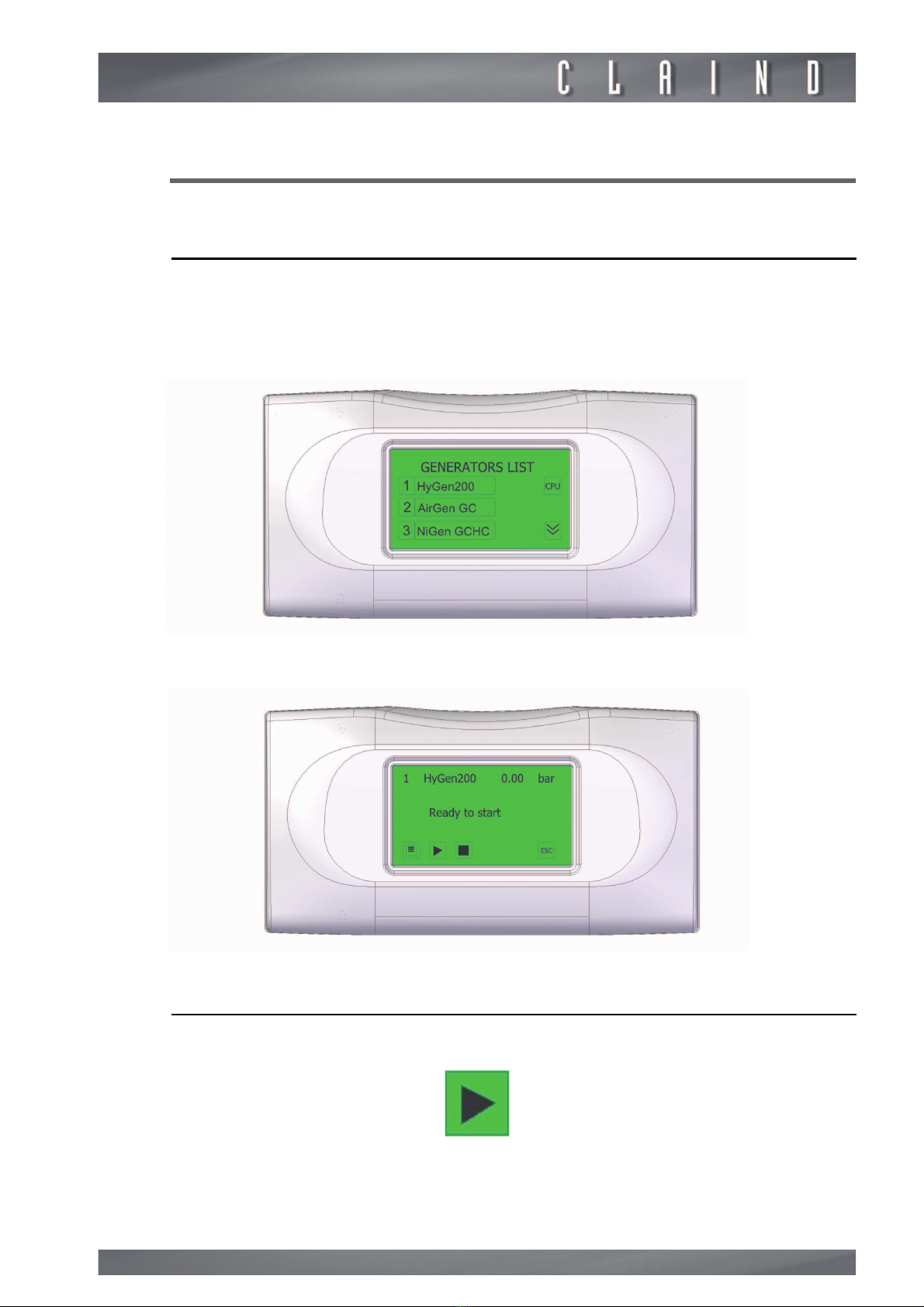
6.1. Generator start-up
To s itch on the generator, put the start button on the rear of the generator on
position I: the CPU screen ill light up.
After a brief appearance of the page ith the LOGO, the “GENERATORS LIST”
page is displayed;
touch the text for the required generator;
the "READY TO START" page ill appear.
6.2. Hydrogen production
To start production, press the "START" operation button;
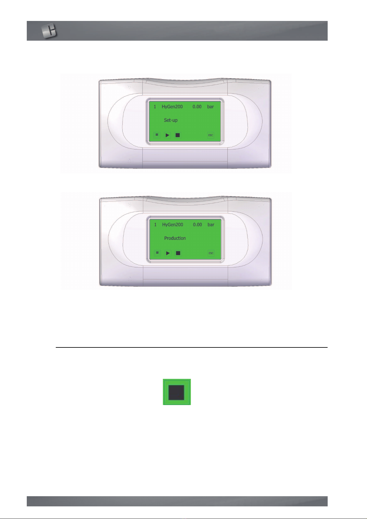
se
20
if coming from start-up, the generator initially carries out a preparation cycle
(SET-UP) lasting about 30 seconds;
on completing set-up, the generator begins to produce hydrogen, sho ing the
follo ing page.
e
WARNING: Some parts of the generator contain air at the first start-up. For this
reason, the line should be vented ith the hydrogen produced (for at least 20
minutes) before using it for the application.
6.3. Stopping the generator
At any time during production the generator can be stopped by pressing the
"STOP" button;
This manual suits for next models
5
Other Claind Portable Generator manuals


Popular Portable Generator manuals by other brands


Briggs & Stratton
Briggs & Stratton 40265 Illustrated parts list

evertz
evertz 7700 Series manual

Briggs & Stratton
Briggs & Stratton 190839GS owner's manual

Wibre
Wibre 5.0635.00.36 installation manual

stayer
stayer GID1000 operating instructions

Briggs & Stratton
Briggs & Stratton 040226-1 Illustrated parts list