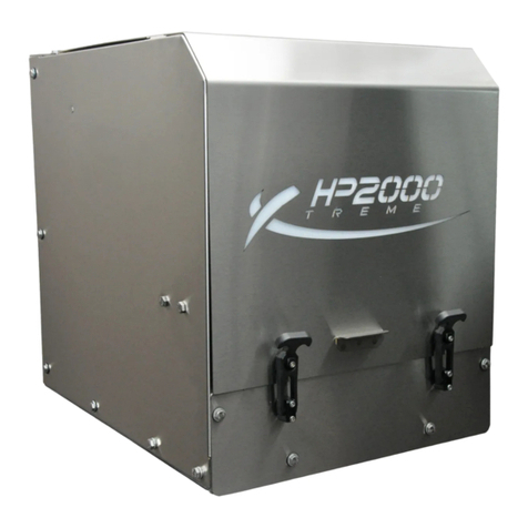
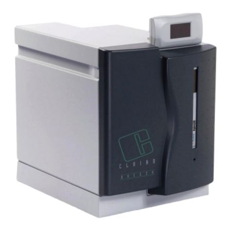
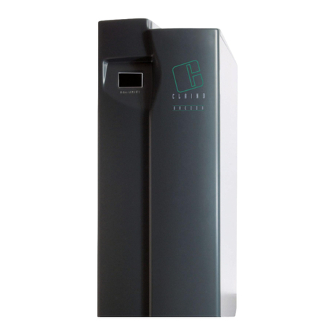
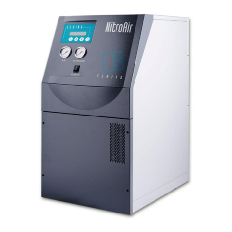
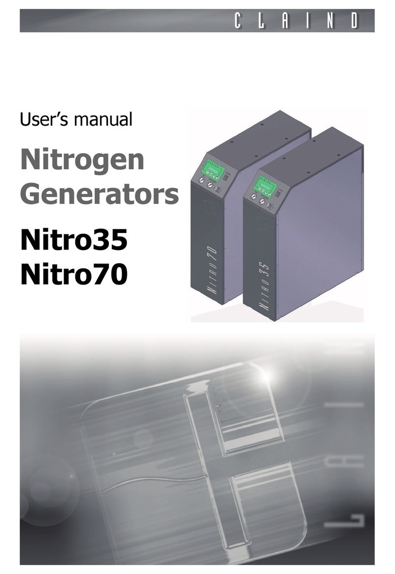
Claind N2 LCMS 1 User manual

User Manual
Nitrogen
generator
N2 LCMS 1

2
Sommario
1. Introduction 3
2. Safety 4
3. Description of the generator 6
4. Installation 8
5. Disasse bly and transport 11
6. Use 12
7. Maintenance 17
8. Troubleshooting 22
9. Guarantee 23

Nitrogen generator N2 LCMS 1
3
1.
Introduction
This docu ent is ai ed at the User of a nitrogen generator odel N2 LCMS 1,
and provides all infor ation regarding installation use and aintenance.
As regards the operations of installation and aintenance, it is presu ed that
the anual User is experiences in the use of pneu atic co ponents, and in par-
ticular is aware of all safety aspects linked to the use of co pressed air and ni-
trogen.
The CE ark guarantees that these generators have been designed and con-
structed in accordance with the following European directives:
• Electro agnetic co patibility: 89/336 EEC
• Low voltage: 73/23 EEC
• Pressure equip ent: 97/23 EEC
• Single pressure vessels: 87/404 EEC
The argin of the text contains the following sy bols, indicating:
m
compulsory safety standards to be observed
c
electrical hazard
e
reco endations and i portant infor ation
It is strongly reco ended to carefully read all safety warnings (par. 2.1.) be-
fore carrying out any operation on the generator.

Safety
4
2.
Safety
The generators in this series can be installed in the vicinity of the utilities without
the require ent for classification of the surrounding area as “hazardous”, provi-
ded that all necessary easures have been taken to guarantee the axi u
safety.
The unit ust be installed and used in observance of the instructions in this boo-
klet. Failure to observe these instructions will render the guarantee null and void
and release CLAIND fro all liability for direct or indirect da age or physical
injury.
2.1.
Warnings
m
lace the generator FAR FROM SOURCES OF HEAT
m
lace the generator in an environment ROTECTED AGAINST RAIN
AND WIND
c
NEVER O EN the generator while it is connected to the electrical
mains. RISK OF FATAL INJURY BY ELECTROCUTION
e
Repairs and inspections ust be carried out exclusively by S ECIALIST ER-
SONNEL: in the event of faults i possible to solve according to one of the pro-
cedures in the TROUBLESHOOTING chapter, contact exclusively a CLAIND
technical service centre
e
If the generator is not to be used for a prolonged period of ti e, it ust be ade-
quately depressurised (see par. 6.5. and par. 6.6.)
2.2.
Notes on the use of nitrogen
Nitrogen is not a toxic gas, but when the percentage in the air exceeds specific
values there is a risk of asphyxia.
Therefore NEVER DIRECTLY INHALE the gas produced and avoid working in the
vicinity of a flow of nitrogen.
However, given the low quantities produced, it is sufficient that the flow of ni-
trogen occurs in a nor ally ventilated environ ent to avoid the risk of accu u-
lation.

Nitrogen generator N2 LCMS 1
5
2.3.
Safety devices
MAXIMUM RESSURE: Pressure levels are constantly controlled by a safety
valve that is activated (without the need for electrical power source) if pressure
values exceed 11.8 bar (1180 kPa).
2.4.
Technical assistance
The CLAIND technical assistance can be contacted as follows:
Tel. ++39 0344 56603
Fax ++39 0344 56627
e- ail: service@claind.it

Description of the generator
6
3.
Description of the generator
3.1.
Equipment supplied
Unless otherwise agreed upon, the supply includes:
• nitrogen generator odel N2 LCMS 1
• User anual
• certificate of confor ity to safety directives
• electric power supply cable (2 ) with socket type IEC350-Schuko
• 1 polya ide pipe 4x2 (drain discharge)
• 1 adapter G1/4 - 10 polya ide pipe
3.2.
Technical specifications
3.2.1.
General
3.2.2.
Electrical
3.2.3.
Gas
The degree of purity of the gas on output varies according to the type of use and
application. The data regarding the present odel are specified on the relative
product datasheet.
Dimensions Width 40 c
Depth 80 c
Height 120 c
Weight 120 kg
ackaging dimensions Width 55 c
Depth 92 c
Height 140 c
Gross weight 135 kg
Noise <65 dB(A)
Operating temperature Between 5°C and
40°C
rotection rating IP20
ower supply voltage
according to odel,
230 VAC (±10%); 1ph; 50Hz
or
115 VAC (±10%); 1ph; 60Hz
Max. absorption 850 VA

Nitrogen generator N2 LCMS 1
7
3.3.
Generator components
3.3.1.
Front view
3.3.2.
Rear view
A. ALPHANUMERIC DISPLAY AND
KEYBOARD: indicates operating status
and alar s; the four keys enable the
display and odification of operating
para eters as required
B. PRESSURE GAUGE: indicates the
output pressure of the nitrogen
C. “POWER” KEY: ON pushbutton
D. LOWER PANEL: access to the filter
zone for aintenance
E. CONNECTOR for electric power
supply cable; includes housing for
ain FUSE
F. OUTLET: pneu atic connection
(G 1/4 fe ale) for nitrogen line
G. DRAIN: coupling for condensate drain
H. LABEL: states the odel, serial
nu ber (SN) and the electrical
specifications
I. LOWER PANEL: access to co pressor
for aintenance

Installation
8
4.
Installation
4.1.
Installation area requirements
4.1.1.
Hu idity and dust
To avoid risks of da age to electronic co ponents, install the generator in an
environ ent subject to li ited relative hu idity and low concentrations of dust.
The generator ust also be protected against drips, rain and wind.
4.1.2.
Te perature
The a bient te perature in the generator installation area ust be between
5°C and 40°C.
Install away fro heat sources. Avoid direct exposure to sunlight.
4.2.
Generator positioning
4.2.1.
Handling
The generator ust be handled by eans of suitable equip ent such as pallet
trucks or lift trucks.
e
The generator ust always re ain in a vertical position as it is not designed to
be laid on its side.
4.2.2.
Packaging re oval
The generator is delivered on a special pallet in carton packaging.
Re ove all packaging, taking care not to da age the generator panels.
If possible, store the packaging to ensure adequate protection when oved in
the future.
4.2.3.
Positioning
When choosing the installation area for the generator, take into account ini-
u clearances required for use and aintenance; ideally a free space should
be left of at least 50 c fro the front and rear panels. The clearance at the
rear of the generator, as well as for aintenance, is required to ensure efficient
cooling of the co pressor.

Nitrogen generator N2 LCMS 1
9
4.3.
neumatic connections
4.3.1.
Nitrogen Outlet
The distribution line ust be ade of pipelines suitable for a pressure of at least
11 bar.
The pipe dia eter ust be sized on the basis of the acceptable pressure drop
values of the utility. Pipelines with an internal dia eter of at least 8 are re-
co ended (e.g. polya ide pipe 10x8 ).
e
If gas is delivered to a line that has not been thoroughly checked for cleanliness,
to avoid the collection and transfer of undesired substances in the nitrogen (oil
residue fro pipe processing, dust, scale, hu idity) and ti es require to obtain
no inal purity are prolonged, cleaning is reco ended, or ensure that pre-
washed and treated pipelines are used when laying the gas distribution lines.
CONNECTION
• Locate the nitrogen coupling (G 1/4 fe ale), arked “OUTLET” at the rear of
the generator.
• Connect the line.
4.4.
Drain
CONNECTION
• Locale the “DRAIN” outlet at the rear of the generator;
• ount the on/off valve and close it (supplied with the generator);
• connect the polya ide pipe 4x1 (supplied with the generator);
• route the other end of the pipe into the condensate collection container.
4.5.
Electric power supply
c
For reasons of safety, the following instructions must be strictly obser-
ved.
The electrical installation ust co ply with current standards, in particular re-
garding the protection line.
c
Recommendations for correct installation:
• do not use extension leads, adaptors or ultiple sockets; if necessary, replace
the plug IEC350-Schuko with a ore suitable version;
• always connect the protection wire;
• the ains socket ust be located in an easily accessible position.

Installation
10
CONNECTION
• Locate power cable connector at the rear of the generator.
• Before connecting the cable, ensure that the POWER key is set to OFF.
• Connect the power cable (length 2 , type IEC350-Schuko) supplied with the
generator.
4.6.
Warnings
e
If a failure in gas supply (due to a power failure, activation of an electrical safety
device, or generator fault), even te porary, is not ad issible, a pneu atic panel
should be envisaged, to enable provisional activation of a reserve gas source (to-
tally or partially auto atic)
e
To ensure co pliance with standards i posed by the Machinery directive, the
start-up of the generator after electrical power supply is restored cannot nor al-
ly be auto atic, and should be anually activated by the operator
e
If auto atic start-up of the generator is necessary, this co and should be en-
tered in the set-up progra
4.7.
ackaging disposal
All packaging aterials used are co patible with the environ ent and ay be
stored without risk, or disposed of and recycled in accordance with local legisla-
tion governing classified waste collection.
However, when possible, it is reco ended to store the packaging to ensure
adequate protection when oved in the future.

Nitrogen generator N2 LCMS 1
11
5.
Disassembly and transport
5.1.
Disassembly
• Stop the generator (see par. 6.5.).
• Wait for depressurisation.
• Switch off the generator (see par. 6.6.).
• Disconnect the electric power cable;
• Close all valves (air inlet, tanks) and detach the pneu atic connections.
5.2.
Transport
e
Re e ber that during transport the generator ust always re ain in a vertical
position.
If conserved, use the original packaging; otherwise use a pallet of adequate di-
ensions to hold the generator, affixing instructions in visible locations, such as:
THIS WAY UP, KEEP IN VERTICAL POSITION.

Use
12
6.
Use
6.1.
Keyboard and display
KEYBOARD
The keyboard on the front panel of the generator enables the user to interact
with the generator, i.e. give specific co ands or display and set para eters.
The table shows the function of the various keys:
DIS LAY
The display co prises 2 lines each of 20 characters
Usually the top line displays the functions or para eters and the lower line di-
splays the relative status and values
If the essage exceeds 20 characters, the text scrolls on display.
Key Function
Function Selects a generator function
Cursor Increases the selected value
Cursor Decreases the selected value
Operation Starts or stops the generator

Nitrogen generator N2 LCMS 1
13
6.2.
Initial start-up
6.2.1.
Configuration
The generator leaves the factory pre-set and ready to start production The user
can access the configuration of a nu ber of para eters (e.g. language, start-up
ode, etc). See section Para eter settings
6.2.2.
Operation sequence
1. Check that all connections are ade as specified in chapter 4 (INSTALLATION)
2. Close the nitrogen line, downline of the generator
3. Switch on the generator, by setting the POWER key to ON (see par. 6.3.
Generator start-up)
4. Start nitrogen production by pressing the key START-STOP (see par. 6.4.
Nitrogen production)
5. IMPORTANT!! When AIR pressure reach 4 bar open the on/off valve at the
DRAIN outlet. For see the AIR pressure gauge re ove the frontal
6. Wait until the generator reaches the Standby status. In this status, the
generator interrupts the nor al production cycles and the display shows the
essage STAND-BY.
7. Fro this point the nitrogen is available for the line, by opening the valve
closed in point 2.
e
WARNING: On initial start-up, the internal nitrogen storage tank will initially con-
tain air: for this reason, the line should be purged (for approx. 20 inutes) be-
fore using the nitrogen.
6.3.
Generator start-up
To switch on the generator, press the black key “POWER” at the front of the ge-
nerator.
The display illu inates and, after a few seconds, a depressurisation cycle is star-
ted auto atically. During this phase, lasting axi u 60 seconds, the following
essage is displayed:
WAIT…
DEPRESSURISATION IN PROGRESS
At the end of depressurisation, the following essage is displayed:
GENERATOR READY
In this condition, the generator is ready to receive the production start-up co -
and (see par. 6.4.) or shutdown co and (see par. 6.6.).

Use
14
6.4.
Nitrogen production
When the generator has co pleted the preparation phase (par. 6.3.) and the
essage
GENERATOR READY
is displayed, nitrogen production can be star-
ted up as follows:
Press the key START/STOP.
The production cycle is started up and the following essage is displayed:
PRODUCTION
e
NOTE: if production is started up after turning on the generator as described in
par. 6.3., the generator runs a nu ber of washing cycles for the olecular sie-
ves before starting up actual production of nitrogen. During this phase, lasting
approx. 15 inutes, the essage
PURGE
is displayed. At the end of this phase,
production will be started up auto atically.
6.5.
Stop the generator
At any ti e during production the generator can be stopped by pressing the key
START/STOP.
Depending on the phase activated, the generator starts to depressurise i e-
diately, or awaits conclusion of the production cycle before activating depressu-
risation.
During depressurisation, which usually lasts fro 30 to 60 seconds, the following
essage is displayed:
WAIT…
DEPRESSURISATION IN PROGRESS
e
NOTE: if a production block alar is active, the START/STOP key is disabled
At the end of depressurisation, the following essage is displayed:
GENERATOR READY
There are then two alternatives:
1. Switch off the generator by pressing the POWER key (see par. 6.6.);
2. resu e the gas production by pressing the key START-STOP (see par. 6.4.)
6.6.
Generator shutdown
6.6.1.
Correct shutdown
Correct shutdown of the generator starts fro the condition of
GENERATOR
READY
. par. 6.5. describes how to reach this condition.

Nitrogen generator N2 LCMS 1
15
Set the "POWER" key (black) to OFF to turn off the generator.
6.6.2.
Incorrect shutdown
Avoid turning off the generator directly, without first shutting down as described
in par. 6.5.
However, this ay occur inadvertently or due to a power failure. In this case, on
subsequent generator restart, the following essage is displayed:
WARNING
INCORRECT SWITCH OFF
To shut off the alar , press the function key .
6.7.
arameter display
6.7.1.
Generator status display
During production, the ain enu displays the essage
PRODUCTION
For ore infor ation on generator status, press the UP key . The following
page is displayed:
AIR N2 YYYY
W.WW X.XX ZZZZ
Where :
W.WW
= air pressure on inlet to sieves, expressed in
bar
X.XX
= nitrogen pressure in the tank, expressed in
bar
YYYY
= operating phase of olecular sieves CMS1
ZZZZ
= operating phase of olecular sieves CMS2
The values are updated continuously to verify correct operation
of the generator
To exit this page and return to the ain enu press the DOWN key .
6.7.2.
Operating hours display
The generator counts the hours of operation (referring to the ti e in which the
generator is in the status
PRODUCTION
), to a axi u value of 65535 hours.
To display the operating hours, return to the ain enu (
PRODUCTION
) and
then press the DOWN key .
To exit this page and return to the ain enu press the UP key .

Use
16
6.8.
arameter settings
”Editing” ode enables the display and entry of para eters that govern gene-
rator operation. They are divided into four categories, with two accessible by the
operator: ode and aintenance
6.8.1.
Editing ode para eters
These para eters select the operating ode of the generator, They co prise:
For access to these para eters, the generator ust be switched on by pressing
and holding the Function key for a few seconds.
The data will be displayed in sequence as shown in the table above.
To odify the value, use arrow keys .
To acquire the set value, press and hold key and press an arrow
key; this confir s the value and oves to the next para eter.
To exit this enu, press and hold the Function key for a few seconds.
6.8.2.
Editing aintenance para eters
See Maintenance section.
Language of messages
Italian
English
Ger an (in preparation)
French
Spanish (in preparation)
roduction restart after incorrect switch off
Manual
Auto atic
Incorrect switch off alarm
Enabled
Disabled

Nitrogen generator N2 LCMS 1
17
7.
Maintenance
To facilitate observance of adequate scheduled aintenance by the user, the ge-
nerator is equipped with a list of co ponents subject to wear, for which, during
the test phase, a working interval is set.
During operation this ti e interval decreases through to expiry, at which point
there is an auto atic request for aintenance.
7.1.
Expiry warnings
During production, if the esti ated autono y of a device expires, a essage is
displayed, an exa ple of which is shown below
.
WARNING
FILTER IN EXPIRY PHASE
To acquire the essage, press function key . The essage is then re oved
to proceed with nor al operation.
On subsequent restart the generator requests whether the aintenance has
been perfor ed, with display of the following essage:
SCHEDULED MAINTENANCE OF FILTER COM-
PLETE?
NO
Press the up arrow key ” to select the answer “YES” or “NO” consecutively.
After selecting the answer, to acquire the essage, press the function key .
If the answer is “NO”, the essage is displayed again on subsequent restart,
while if “YES”, the new work ti e for the co ponent is set (that set on start of
the count) for future aintenance.
If an incorrect shutdown alar is displayed on activation of the generator, this
procedure is disabled; it will be available for subsequent start-up.
7.2.
Maintenance schedule
To aintain generator efficiency and reduce the risks of faults, strictly observe
the reco ended aintenance schedule.
The following table specifies the frequency of the reco ended aintenance
operations, expressed in “operating hours” of the generator.

Maintenance
18
All spare parts required for 2000 hour aintenance are included in the consu-
able parts kit.
For odel LCMS-1, scheduled aintenance is also reco ended for the co -
pressor ( odel 2750 THI 52/48), every 4,000 hours of operation.
7.3.
Compressor inlet filter
The air delivered to the co pressor is taken fro the surrounding environ ent
via a filter ele ent; this has the dual function of filtering air fro dust and solid
particles and da pening the noise generated by intake.
The frequency of operations on this co ponent depends greatly on the quantity
of dust present in the a bient air.
Component Replacement frequency
Co pressor inlet filter 2,000 hours
Coalescence filter 2,000 hours
Silencer filters 2,000 hours
General overhaul 4.000 hours
RE LACEMENT
• Turn off the generator as described in
par. 6.5. Stop the generator and par.
6.6. Generator shutdown
• Disconnect the power cable then re-
ove the rear lower panel by loose-
ning the fixing screws (see figure
alongside)
• Locate the filter: this is a black plastic
cylinder connected horizontally to the
head section of the co pressor
• Unscrew the filter by hand and check
for clogging; if excessive, replace.
• Refit the filter on the coupling of the
co pressor head section. Sealing
co pound on the threads are not re-
quired
• Close the generator and reconnect the
power cable
• The generator can now be restarted.

Nitrogen generator N2 LCMS 1
19
7.4.
Coalescence filter
The air filter contains the actual filter
ele ent, which with use can gradually
clog up, i pairing correct operation of
the instru ent.
RE LACEMENT
With reference to the drawings illu-
strating the internal layout of the co -
ponents, the filter ele ent or entire
filter body is easily replaced, according
to the procedure described below.
• Turn off the generator as described in
par. 6.5. Stop the generator and par.
6.6. Generator shutdown;
• Disconnect the power cable then re-
ove the front lower panel by loose-
ning the fixing screws (see figure at
top)
• Locate the filter A, positioned at the
centre of the generator.
• Withdraw the drain hose B fro the
coupling on the lower section of the
bowl.
• Loosen the bowl by turning it anti-
clockwise.
• Re ove the spent cartridge C
• Insert the new cartridge
• Tighten the bowl.
• Refit the hose B in the coupling.
• Close the generator and reconnect the
power cable.
• The generator can now be restarted.

Maintenance
20
7.5.
Vent silencer filters
The vent silencers are fitted on solenoid valves which depressurise the olecular
sieves during regeration. The vent silencers are used to da pen the noise ge-
nerated by the high speed delivery of gas fro the solenoid valve.
7.6.
Main fuse
The generator is protected by eans of a fuse located in the electric power soc-
ket.
For replace ent proceed as follows:
RE LACEMENT
• Turn off the generator and disconnect
the power cable; re ove the front
lower panel by loosening the fixing
screws.
• Locate the position of the solenoid val-
ves, at the lower left and right of the
generator.
• Locate the cylindrical silencers A and
B, placed vertically above the solenoid
valves.
• Turn the silencers anti-clockwise to lo-
osen and replace with new ones.
• Close the instru ent and reconnect
the power cable.
• The generator can now be restarted.
• Re ove the power cable fro the soc-
ket
• Extract the fuse box A fro the socket
• Replace the faulty fuse
• Refit the box and cable in the socket
• The generator can now be restarted.
Other Claind Portable Generator manuals
Popular Portable Generator manuals by other brands
Black Max
Black Max BM903000A Quick reference guide

DUROMAX
DUROMAX DUAL FUEL SIDE KICK XP2200EH user manual

Jupiter Avionics
Jupiter Avionics JA37-300 Installation and operating manual

BE
BE BE1200I user manual

SIGLENT TECHNOLOGIES
SIGLENT TECHNOLOGIES SDG7000A Series Service manual

MULTIQUIP
MULTIQUIP WhisperWatt DCA45SSKU3 Operation and parts manual