Clairvoyant C2190D User manual

C2190D
H.264DECODER
StandAlone
Decoder
MANUAL
Firmware 2.2.0.5 Version

Revision Date : 2009.06.01
Trademarks and/or registered trademarks are the property of their respective owners
The information presented in this publication has been carefully prepared and is
believed to be correct at the time of publication. However, no responsibility will be
assumed for any inaccuracies. Specifications are subject to change without notice.
The information contained herein is the property of MWR Engineering Co., Ltd., and
shall not be reproduced in whole or in part without prior written approval of MWR
Engineering Co., Ltd., The information herein is subject to change without notice and
should not be construed as a commitment by MWR Engineering Co., Ltd.. This
manual is periodically reviewed and revised.
MWR Engineering Co., assumes no responsibility for any errors or omissions in this
document. Critical evaluation of this manual by the user is welcomed. Your comments
assist us in preparation of future documentation. A form is provided at the back of the
book for submitting your comments.
Copyright 2005–2010 by MWR Engineering Co., Ltd. All rights reserved.
Package List:
1 2190D (one)
2 DC 12V Power adapter (one)
3 Remote Controller (one)
4 CDROM Disc (TVWALL & Manual) (one)
Instruction:
NVD: NetworkVideoDecoder
Click: Click on the left key of the Mouse
Double- Click: Click on the left key of the Mouse Twice
WARNING: If the actions indicated in a
“WARNING” are not complied with, injury or
major equipment damage could result. A
warning statement typically describes the
hazard, its possible effect, and the measures that must be
taken to reduce the hazard.
CAUTION: If the action specified in the
“CAUTION” is not complied with, damage to
your equipment could result.
NOTE: A “NOTE” provides supplementary information,
emphasizes a point or procedure, or gives a tip for easier
operation.
CAUTION:
Any changes or modifications not expressly
approved by the party responsible for
compliance could void the user’s authority to
operate the equipment.
NOTE: This equipment has been tested and found to comply with the
limits for a class digital device, pursuant to part 15 of the FCC Rules.
These limits are designed to provide reasonable protection against
harmful interference when the equipment is operated in a commercial

environment. This equipment generates, uses, and can radiate radio
frequency energy and, if not installed and used in accordance with the
instruction manual, may cause harmful interference to radio
communications. Operation of this equipment in a residential area is
likely to cause harmful interference in which case the user will be
required to correct the interference at his own expense.
Disposal of Old Electrical & Electronic Equipment
(Applicable in the European Union and other
European countries with separate collection
systems)
This symbol on the product or on its packaging indicates that this
product shall not be treated as
household waste. Instead it shall be handed over to the applicable
collection point for the recycling of electrical and electronic
equipment. By ensuring this product is disposed of correctly, you will
help prevent potential negative consequences for the environment
and human health, which could otherwise be caused by
inappropriate waste handling of this product. The recycling of
materials will help to conserve natural resources. For more detailed
information about recycling of this product, please contact your local
city office, your household waste disposal service or the shop where
you purchased the product.

• Make sure not to connect the power before you install the
NVD.
• There is great chance of damaging your NVD if the NVD is
opened by an unqualified service engineer or installer.
• Avoid using the NVD under direct sunlight (tropical area,
Middle East), or near to any source of heat.
• Don’t merge the NVD under water; always put silicon gel
on antenna connector after installation to avoid corrosion
and reducing the wireless link capability.
• Avoid exposing the NVD to violent movement or vibration.
• Always use the NVD in a well ventilated location to
prevent overheating.
• Connect proper “Relay” between load and NVD, to protect
NVD, don’t connect load greater than 0.5A.
• Please use power adapter equipped with the NVD, foreign
power adapter with wrong voltage may permanent
damage your NVD.
All the safety and operating instructions must be read before the unit is operated.

Table of Contents
1Key Features.............................................................................................. 7
1.1 Brief Introduction............................................................................. 7
1.2 Features ............................................................................................ 7
1.3 Topologies ........................................................................................ 8
2 Appearance and Installation ...................................................................... 10
2.1 Front-end Panel .............................................................................. 10
2.2 Back-end Panel............................................................................... 10
2.3 Installation.......................................................................................11
3 USE .......................................................................................................... 12
3.1 Remote-controller........................................................................... 12
3.2 Main-Interface................................................................................ 13
3.3 Structure of System Menu.............................................................. 14
3.4 Soft-Keyboard Operation ............................................................... 14
3.4 Main-Menu..................................................................................... 15
3.5 Connection...................................................................................... 16
3.6 Disconnect...................................................................................... 17
3.7 Recycle Connect............................................................................. 17
3.8 Recycle Setup................................................................................. 18
3.9 System Setup.................................................................................. 19
3.10 Directory....................................................................................... 23
3.11 Alarm Linkage.............................................................................. 24
3.12 Alarm Query.............................................................................. 25
Appendix I FAQ.......................................................................................... 26
Appendix II Decoder Setup by PC Software.......................................... 27

Clairvoyant 2190D
7/ 31
1Key Features
1.1 Brief Introduction
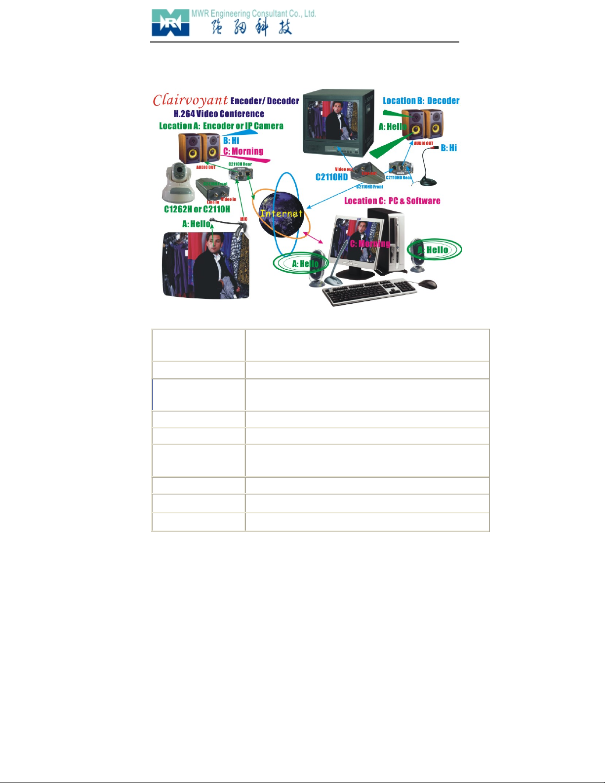
Network Video Decoder is an embedded surveillance device designed for network application .It
uses the most mature and high reliability exclusive DSP solution in the industry together with powerful
RTOS (Real-time Operating System) to actually realize industry grade MTBF (Mean Time Between
Failure).All of the encoders in our company are compatible with it(NVD).It needn’t PC platform, receiving
digital audio &video signal from the network directly then transcoding it output to the TV Wall. It can carry
on the pronunciation and talk-back with the encoder at the same time. Built-in GUI(Graphic User
Interface),support Remote Controller, Keyboard or Matrix, operate conveniently and simply.
1.2 Features
-High reliability special DSP solution, super powerful RTOS, realize industrial grade MTBF
-Support 4-channel CIF & Single-channel D1 decoding
-Support point-to-point communication.
-Support point-to-multi-point communication.
-Support Passive Mode(Receive digital signal from PC or other devices, output after decoding)
-Support Keyboard or Matrix control input
-Support PAL/NTSC Video output
-Support remote device upgrade safely function
-Support Dynamic IP Address (DHCP) & DNS
-Auto-recovery function if exception occurs and auto-connection if the network interrupts
Clairvoyant 2190D
8/ 31
1.3 Topologies
1.4 Te
c
hn
i
c
a
l
S
p
e
c
i
f
i
c
a
t
i
on
:
Video Definition PAL: 352*288 (CIF), 704*288 (2CIF), 704*576 (D1);
NTSC: 352*240 (CIF), 704*240 (2CIF), 704*576 (D1)
Video Compression H.264 Main Profile@ Level 3
Decode Frame Rate PAL: 25 fps 2CIF x 4 channels or 25fps D1 x 2 channels
NTSC: 30 fps 2CIF x 4 channels or 30fps D1 x 2 channels
Video Parameters Brightness, Hue, Contrast, Saturation, Image quality.
Streaming Format Video Streaming or Audio & Video composite Streaming
Video Output 1 composite BNC video output, PAL or NTSC; level: 1.0Vp-p,
impedance: 75Ω,
Audio Compression G.726
Audio Output 1 x channel, RCA port, linear output
Audio talk-back input 1 x channel, MIC port

Clairvoyant 2190D
9/ 31
Communication Ports 1x 10M/100M Ethernet port, 1 x RS485 port, 1 x RS232 port
Alarm Input 2 channel on/ off input, supporting NO (Normally Open) or NC
(Normally Close) sensors
Alarm Output 4 channel on/ off output, 120VAC 1A/ 24VDC 1A
Power Supply DC 12V, 1.5A
Maximum Power Less than 15W
Operating Temperature -10 ~ +55 ℃
Storage temperature -22 ~ +70 ℃
Operating Humidity 10 ~ 85%
Operating system Microsoft Windows 98/ME/2000/XP/2003/Vista/7
Processor SOC single chip solution (ARM9 & DSP)
Weight 1.5 kg
Dimensions 205mm(L) * 50mm(H)* 130mm(D)
Clairvoyant 2190D
10/ 31
2Appearance and Installation
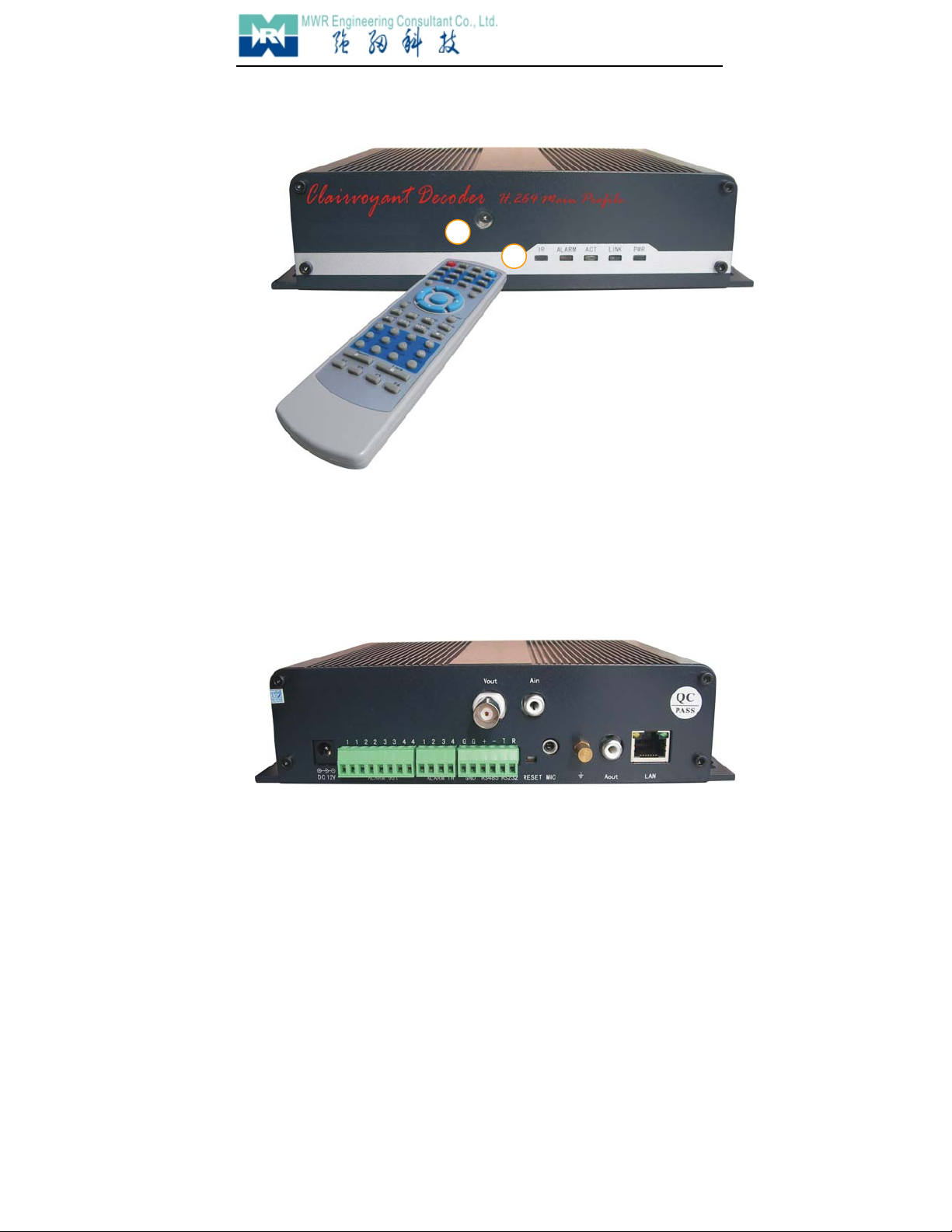
2.1 Front-end Panel
PWR:PowerIndicatorLight LINK:Network Connection Indicator Light
ACT:Network Transmission Indicator Light ALARM:Alarm Indicator Light
cRemote -control Indicator Light
dWindow of Remote-control Receiver
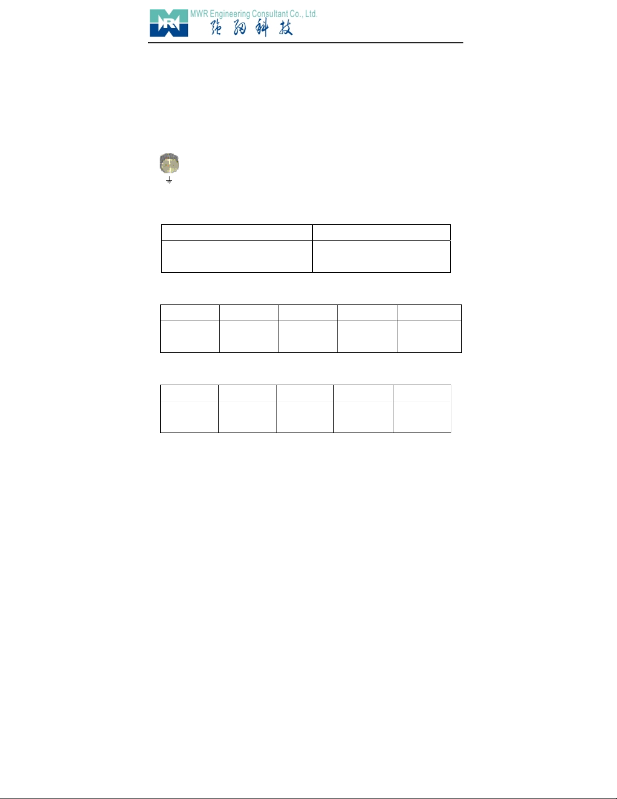
2.2 Back-end Panel
Back-end Panel Image of Decoder
Instruction:
2
1
Clairvoyant 2190D
11/ 31
1. Vout:Composite Video Output
3. DC12V:Power Supply Input, DC12V(1A).
4. MIC:Microphone Input
5. LAN:(ETHERNET) Network Interface
6. RESET:All parameter restore to default value after press it.
Notice:Please don’t press RESET if you are not professional operator.
7.Aout:Audio Output Interface
8. Nut : Prevent from being damaged by thunder
Notice: Connect it to the Lab network system correctly.
9. ALARM OUT:Double-channel Alarm Output
10. ALARM IN:Four-channel Alarm Input (Standby: Ready and waiting)
1 2 3 4 G
First Alarm Input Second Alarm
Input
Third Alarm
Input
Fourth Alarm
Input
Public Area of
Alarm Input
11. RS485 RS232:Two Independent Serial Interface
G + - T R
Public Area of
Serial Interface
RS485 Positive
End
RS485
Negative End
RS232 Send
Port
RS232 Receive
Port
2.3 Installation
1. Connect the NVD to your network or use network access line connect it to your PC directly.
2. Connect Vout & Aout of NVD to monitor.
3. Put through Power Supply (DC12V)
4. Connection Light (Orange) will be on in five seconds under normal condition, then it indicates
your physical connection of NVD has been finished successfully.
1 – 1 2 -- 2
First Relay Output(1A 120VAC/1A 24VDC)Second Relay Output (1A 120VAC/1A
24VDC)
Clairvoyant 2190D
12/ 31
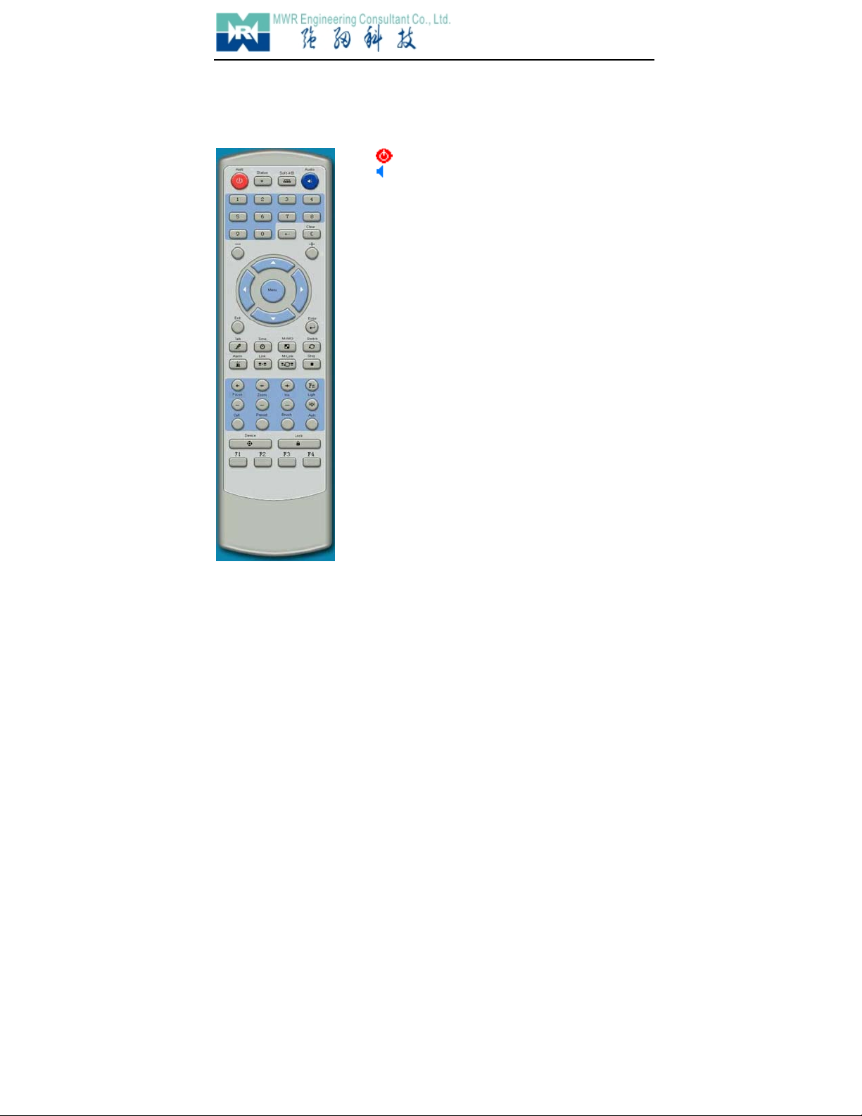
【】 Power ON/OFF
【】 Audio Monitor ON/OFF
【Status】 Display System Information
【Soft-KB】 Open/Close Soft Keyboard
【0 - 9】NumKey
Num-Input under Menu Status
Channel-selection Input under Non-Menu
Status
【
<——
】Tab
【C】Clear
【+ -】Plus\Minus PageUp/PageDown
【】 Cursor Moving
PTZ Control
【Exit】 Exit
【Enter】 Enter
【Menu】 Open/Close Operating Interface
【Talk】 Open/Close Talk-back
【Time】 Time&StatusDisplayOn/Off
【Multi-image】Pre-view Mode Select(Multi-image)
【Switch】 Channel Alt
【Clear Alarm】 CleanAlarmInformation
【M-IMG】 Open Operating Interface of Single-channel
Connection
【M-Link】 Open Operating Interface of Multi-channel
Connection
【Stop】 Stop all connection
【FocusZoomIris】Focus,Zoom,Iris
【Light】 Light Control
【Brush】 Brush Control
【Auto】 PTZ&Dome Automatic-control
【PresetCall】 High-speed Dome Preset.
【Device】Correlative NVD can be controlled by
Remote-controller.
【Lock】 Logoff
【F1 F2 F3 F4】 Standby
【Fn】 Refresh
3 USE
3.1 Remote-controller

Clairvoyant 2190D
13/ 31
3.2 Main-Interface
Figure appears as follows after put through the Power Supply.
All DVS (Digital Video Server/ IP Camera) of our company can be connected.
System Time Monitor Talk-back
AlarmConnection
Clairvoyant 2190D
14/ 31
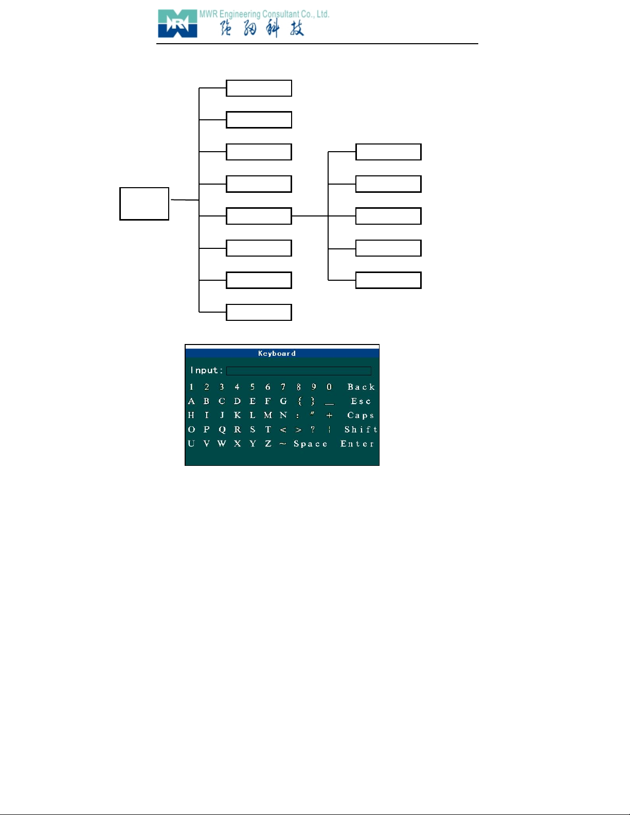
3.3 Structure of System Menu
3.4 Soft-Keyboard Operation
Press Soft Keyboard to input “User’s Name”, “URL”.
InputInput Box
BackBack Space
EscCancel&Exit
CapsCaps Alt
ShiftFunction Key
Main
Menu
Link
Shut
MLink
MSet
Set
ABook
Alarm
Alert
System Time
Network Setup
Save Parameter
System Information
System Parameter
Clairvoyant 2190D
15/ 31
EnterEnter
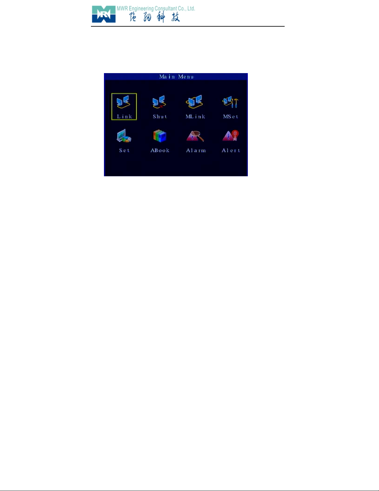
3.4 Main-Menu
Figure appears as follows after press Menu
Instruction:
LinkEnter Operating Interface of Single-channel Connection
ShutDisconnect Single-channel or Recycle connection
MLinkEnter Operating Interface of Recycle Connection
MSetEnter Interface of Recycle Setup
SetEnter Interface of System Setup
ABookEnter Operating Interface of Directory
AlarmEnter Interface of Alarm Query
AlertEnter Interface of Alarm Linkage Setup

Clairvoyant 2190D
16/ 31
3.5 Connection
Move the cursor to Connect, press Enter, figure appears as follows:
◆Name:
Only if when opened DDNS (Set it in Network Parameter) but can’t connect to DVS by URL
then use this parameter.
◆URL:
Move cursor to “URL”, press Num Key input IP address, press 【*】input “.”,press 【Soft
Keyboard】, Soft Keyboard will appears, then input domain name of the DVS, the length is
1-32.
◆Communicate Port:
Corresponded to the port setted in DVS.Move cursor to “Service Port”,press Numeric Key
input port number or press 【+】、【-】change it.
◆Channel
Connect channel of the DVS, move cursor to “Channel”, press 【+】、【-】select channel.
◆Transmit Mode
“WAN” , “LAN” can be selected. Move cursor to “Transmit Mode”, press 【+】、【-】change it.
◆User’s Name:
Move cursor to “User’s Name”, press 【Soft Keyboard】,input User’s Name then press
Clairvoyant 2190D
17/ 31
【Enter】
◆Password
Move cursor to “Password”, press 【Soft Keyboard】,input password then press 【Enter】
◆Auto-connect
Auto-connection if the network interrupts
◆Directory
Move cursor to “Directory” and select DVS if necessary
3.6 Disconnect
Move cursor to Disconnect, press 【Enter】close all connections.
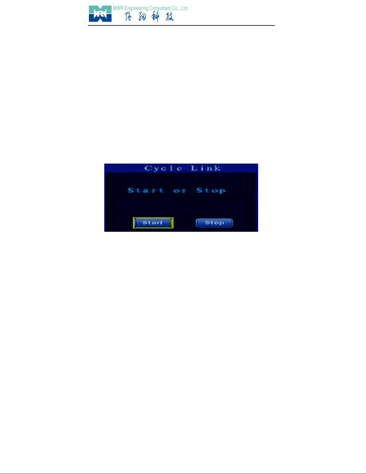
3.7 Recycle Connect
Press Recycle Connect, then press 【Enter】, figure appears as follows:
Move cursor to “Start”, then press “Enter” open recycle-connection, move cursor to “Stop” close all
recycle-connection.
Recycle-connection can realize connecting many DVS to one Decoder. Users can set up different
delay time according to different application. Device will connect DVS automatically after start
Recycle-connection.

Clairvoyant 2190D
18/ 31
3.8 Recycle Setup
Move cursor to Recycle Setup,press 【Enter】then figure appears as follows:
◆URL:
Move cursor to “URL”, press Num Key input IP address, press 【*】input “.”,press 【Soft
Keyboard】, then input domain name of the DVS, the length is 1-32.
Clairvoyant 2190D
19/ 31
◆Port
Move cursor to “Port”, press Num Key input port number.
◆Transmit Mode
“WAN” , “LAN” can be selected.
Move cursor to “Transmit Mode”, press 【+】、【-】change it.
◆Channel
Move cursor to “Channel”, press Num key input channel number.
◆User’s Name
Move cursor to “User’s Name”, press 【Soft Keyboard】input User’s Name, then press
【Enter】,the length is 1-8.
◆Password
Move cursor to “Password”, press【Soft Keyboard】,input password then press【Enter】.the
length is 1-8
◆Delay Time
Move cursor to “Delay Time”, press Num Key input delay time, from 5-1800 seconds.
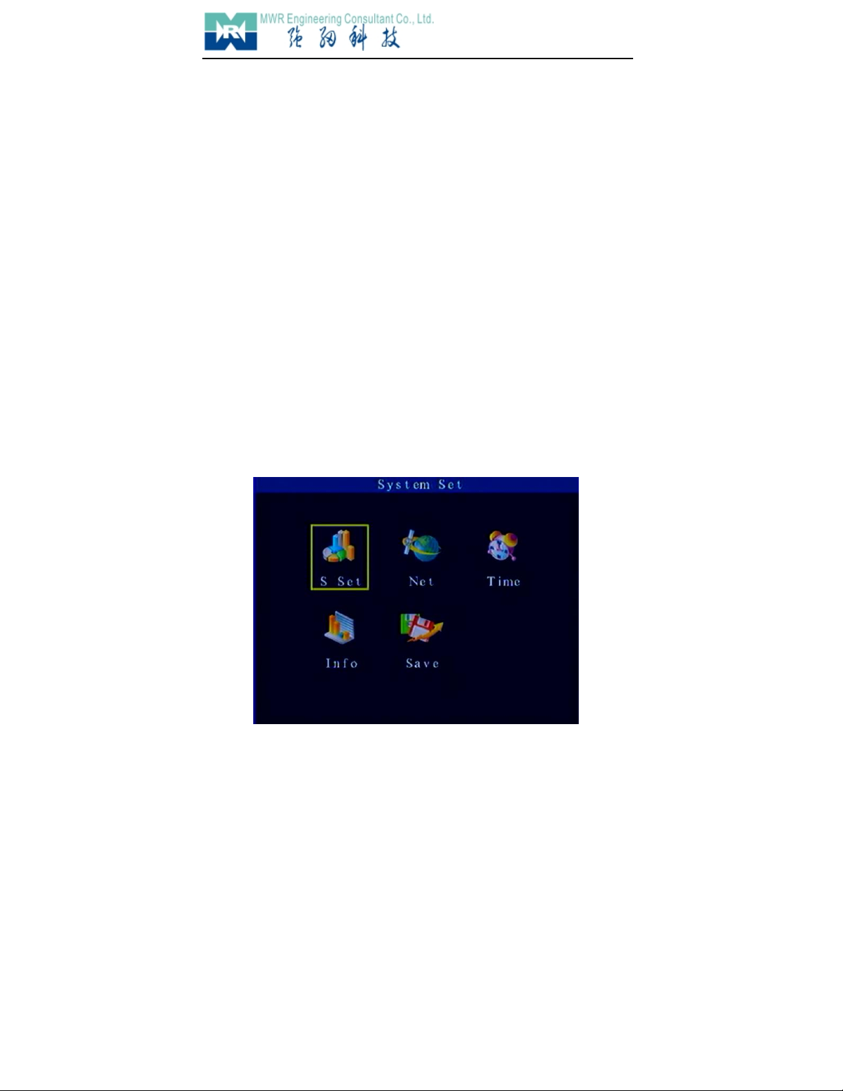
3.9 System Setup
Move cursor to System Setup, press 【Enter】,figure appears as follows:

Clairvoyant 2190D
20/ 31
Instruction:
System ParameterEnter System Parameter Setup Interface.
Netware SetupEnter Netware Parameter Setup Interface
System TimeEnter System Time Setup Interface
System InformationDisplay System Information
Save ParameterSave all parameter
3.9.1 System Parameter
Move cursor to System Parameter, press 【Enter】, figure appears as follows:
◆Standard of Video Output
Move cursor to “Standard of Video Output”, press 【+】【-】select PAL or NTSC
◆Language
Move cursor to “Language”, press 【+】【-】select English or Chinese.
Note: System will restart automatically after changed.
◆Device ID:
When there are lots of NVD put together, in order to control the apparatus separately with
the remote controller, you need to number each apparatus, then choose corresponding
apparatus through the remote controller.
◆RS485 Address
Table of contents


